EP1070465A2 - Device for storing and applying a product to eyelashes or eyebrows - Google Patents
Device for storing and applying a product to eyelashes or eyebrows Download PDFInfo
- Publication number
- EP1070465A2 EP1070465A2 EP00402086A EP00402086A EP1070465A2 EP 1070465 A2 EP1070465 A2 EP 1070465A2 EP 00402086 A EP00402086 A EP 00402086A EP 00402086 A EP00402086 A EP 00402086A EP 1070465 A2 EP1070465 A2 EP 1070465A2
- Authority
- EP
- European Patent Office
- Prior art keywords
- teeth
- applicator
- fact
- base
- bases
- Prior art date
- Legal status (The legal status is an assumption and is not a legal conclusion. Google has not performed a legal analysis and makes no representation as to the accuracy of the status listed.)
- Granted
Links
- 210000000720 eyelash Anatomy 0.000 title claims description 27
- 210000004709 eyebrow Anatomy 0.000 title claims description 9
- 238000000926 separation method Methods 0.000 claims abstract description 18
- 239000004033 plastic Substances 0.000 claims abstract description 13
- 229920003023 plastic Polymers 0.000 claims abstract description 13
- 239000002537 cosmetic Substances 0.000 claims abstract description 5
- 239000000463 material Substances 0.000 claims description 14
- 239000000835 fiber Substances 0.000 claims description 5
- 238000000465 moulding Methods 0.000 claims description 5
- 238000007789 sealing Methods 0.000 claims description 5
- 235000008429 bread Nutrition 0.000 claims description 4
- 239000007787 solid Substances 0.000 claims description 4
- 239000006260 foam Substances 0.000 claims description 3
- 239000000047 product Substances 0.000 description 56
- 230000000694 effects Effects 0.000 description 6
- 238000000034 method Methods 0.000 description 5
- 238000010137 moulding (plastic) Methods 0.000 description 5
- 230000003247 decreasing effect Effects 0.000 description 3
- 241000283986 Lepus Species 0.000 description 2
- 239000011248 coating agent Substances 0.000 description 2
- 238000000576 coating method Methods 0.000 description 2
- 229920001971 elastomer Polymers 0.000 description 2
- 239000000806 elastomer Substances 0.000 description 2
- 238000005299 abrasion Methods 0.000 description 1
- 239000006096 absorbing agent Substances 0.000 description 1
- 238000005452 bending Methods 0.000 description 1
- 239000006227 byproduct Substances 0.000 description 1
- 230000006835 compression Effects 0.000 description 1
- 238000007906 compression Methods 0.000 description 1
- 150000001879 copper Chemical class 0.000 description 1
- 210000003128 head Anatomy 0.000 description 1
- 238000010438 heat treatment Methods 0.000 description 1
- 239000006249 magnetic particle Substances 0.000 description 1
- 238000004519 manufacturing process Methods 0.000 description 1
- 239000002184 metal Substances 0.000 description 1
- 229910052751 metal Inorganic materials 0.000 description 1
- 239000004810 polytetrafluoroethylene Substances 0.000 description 1
- 229920001343 polytetrafluoroethylene Polymers 0.000 description 1
- 239000000843 powder Substances 0.000 description 1
- 239000003755 preservative agent Substances 0.000 description 1
- 230000000717 retained effect Effects 0.000 description 1
- 150000003839 salts Chemical class 0.000 description 1
- 239000012748 slip agent Substances 0.000 description 1
- 239000012265 solid product Substances 0.000 description 1
- 238000004381 surface treatment Methods 0.000 description 1
- 239000002966 varnish Substances 0.000 description 1
Images


Classifications
-
- A—HUMAN NECESSITIES
- A46—BRUSHWARE
- A46B—BRUSHES
- A46B9/00—Arrangements of the bristles in the brush body
- A46B9/02—Position or arrangement of bristles in relation to surface of the brush body, e.g. inclined, in rows, in groups
- A46B9/021—Position or arrangement of bristles in relation to surface of the brush body, e.g. inclined, in rows, in groups arranged like in cosmetics brushes, e.g. mascara, nail polish, eye shadow
-
- A—HUMAN NECESSITIES
- A45—HAND OR TRAVELLING ARTICLES
- A45D—HAIRDRESSING OR SHAVING EQUIPMENT; EQUIPMENT FOR COSMETICS OR COSMETIC TREATMENTS, e.g. FOR MANICURING OR PEDICURING
- A45D40/00—Casings or accessories specially adapted for storing or handling solid or pasty toiletry or cosmetic substances, e.g. shaving soaps or lipsticks
- A45D40/26—Appliances specially adapted for applying pasty paint, e.g. using roller, using a ball
- A45D40/262—Appliances specially adapted for applying pasty paint, e.g. using roller, using a ball using a brush or the like
- A45D40/265—Appliances specially adapted for applying pasty paint, e.g. using roller, using a ball using a brush or the like connected to the cap of the container
- A45D40/267—Appliances specially adapted for applying pasty paint, e.g. using roller, using a ball using a brush or the like connected to the cap of the container comprising a wiper
-
- A—HUMAN NECESSITIES
- A46—BRUSHWARE
- A46B—BRUSHES
- A46B2200/00—Brushes characterized by their functions, uses or applications
- A46B2200/10—For human or animal care
- A46B2200/1046—Brush used for applying cosmetics
- A46B2200/1053—Cosmetics applicator specifically for mascara
- A46B2200/106—Cosmetics applicator specifically for mascara including comb like element
Definitions
- the present invention relates to the application of a product, in particular cosmetic, on eyelashes or eyebrows.
- the invention particularly relates to a new device for applying a product on the eyelashes or the eyebrows, comprising a container for containing a reserve of product and an applicator comprising an application element having at at least one row of teeth, the latter comprising a succession of consecutive teeth, each tooth of this succession of teeth comprising a base and a portion extending from the base.
- This device is characterized by the fact that the basics of said consecutive teeth are substantially aligned and by the fact that the portions extending from the bases of said consecutive teeth are offset alternately on either side of a geometric separation surface.
- the applicator according to the invention preferably comprises a rod, with at least one row of a succession of consecutive teeth arranged at one end of the stem.
- the teeth can be produced by plastic molding.
- substantially aligned bases it should be understood that a portion of each of the bases of the consecutive teeth is arranged on a first side of a line passing through the bases of consecutive teeth, and another portion of each of the bases consecutive teeth is arranged on a second side of the aforementioned line, opposite on the first side, this line being substantially parallel to a longitudinal axis of a base on which the teeth are arranged.
- the consecutive teeth are arranged so that a straight line passes through the centers of each of the bases of consecutive teeth. So the centers of the bases of three consecutive teeth may lie on the same straight line.
- the teeth can be made with a small gap at their base, of so that the eyelashes can be effectively gripped between two consecutive teeth, while having a greater spacing between their free ends, favoring the engagement of the eyelashes between the teeth and the constitution of product reserves on the application element.
- the geometrical arrangement of the teeth also allows fibers to small dimensions, possibly contained in the product, to align so to be substantially parallel to each other when the product is applied, or when the teeth are engaged through a wiping member, or both. This alignment results from a funneling effect between two consecutive teeth.
- the spacing between the bases of two consecutive teeth is preferably less than or equal to 0.4 mm.
- the geometric separation surface passes through the centers of the bases of the teeth.
- the application element comprises a base.
- the teeth are produced by plastic molding in one piece with the base.
- the base can be attached to the applicator rod and the base can have its axis parallel or not to that of the applicator rod.
- the base can be removably attached to the stem of the applicator.
- the geometric separation surface can be a plane, preferably a plane of symmetry for the base.
- the geometric separation surface is a joint plane for molding the teeth and / or the application element.
- the geometric separation surface can be non-planar, for example twisted.
- the geometric separation surface can thus be a helical surface or a curved surface, for example.
- the height of the base of the teeth can be greater than or equal to 0.2 mm, for example.
- the applicator stem may be flat or substantially cylindrical or present yet other configurations, depending on the desired effects and the desired ergonomics.
- the rod may have a connector at its distal end in which the base can be engaged in a removable manner.
- the connector comprises a housing defining a slot arranged to receive the base.
- the housing may have a longitudinal axis which is parallel to the axis of the rod or make an angle with it, the longitudinal axis of the housing being for example substantially perpendicular to the longitudinal axis of the rod.
- the slot which receives the base also receives the bases of the teeth, and the slot may engage the bases of the teeth.
- the base can also be produced by plastic molding in one piece with the applicator rod.
- the application element can be produced by plastic molding in one piece with the applicator rod and with a sealing member intended to ensure a tight closure of the container in the absence of use, this sealing member which may have a shaped surface to adjust so waterproof in a container neck.
- the container comprises a wiping member arranged to remove excess product from the teeth when the applicator is removed from the container.
- This wiper member is preferably deformable.
- a closure cap is disposed at one end of the applicator opposite the end comprising the teeth, this closure cap being intended to close the container containing the product to be applied.
- This closure cap may be provided with a sealing means for seal the container.
- At least two teeth consecutive may have free ends that diverge, converge, intersect or are substantially parallel.
- one tooth on at least two consecutive teeth may have a free end which diverges away from the free end of the other tooth, this other tooth possibly having a free end which is substantially straight.
- At least two consecutive teeth may have free ends which are substantially aligned.
- the applicator element may include teeth having free ends oriented towards a proximal end of the applicator, arranged alternately with teeth having free ends oriented towards a distal end of the applicator.
- the teeth can form between them a housing of substantially axis parallel to that of the base.
- This housing can accommodate an element for interior application such as a brush of the twisted core type.
- the applicator element may have only one row of teeth and make up a comb.
- the applicator element can also have several rows of teeth arranged at different angular positions around the applicator and constitute a brush.
- the application element can comprise for example a second row of teeth opposite the first.
- the application element can also include, for example, a base of polygonal cross section or not. At least one row of teeth extends from preferably substantially in the extension of one side of the base in the case of a polygonal section. In the case of a non-polygonal section, for example circular or elliptical, the bases preferably connect substantially tangentially at the base.
- An application element having such a configuration allows use the base to apply the product and the contact of the eyelashes with the teeth can be done gradually. An application element with this structure can still allow to lengthen and curl the eyelashes.
- the application element can be more flexible than the rod.
- the application element can be made, for example, from a plastic material softer than that used to make the applicator stem. We can thus get more comfort in use.
- the applicator rod can be made of a plastic material less hard than that used to make the application element. We can thus use for manufacturing reasons for example a relatively hard material to make the application element and compensate for the element's hardness of application at the time of application by the flexibility of the rod.
- the teeth can also be made of a material different from that used to make the base.
- the height of the teeth can be variable.
- the height of the teeth is between 0.5 and 15 mm approximately, and more preferably between 7 and 13 mm approximately.
- the invention also relates to an applicator for applying a product to eyelashes or eyebrows comprising a rod and a base disposed at one end of the stem.
- This applicator further comprises at least one row of teeth having bases arranged on the base and portions extending from the bases. The basics of consecutive teeth are substantially aligned and the portions extending from bases of consecutive teeth are arranged on either side of a geometric surface of seperation.
- the width of the base is preferably greater than the width of the bases.
- a second row of teeth can also be arranged on the base. This second row of teeth can be arranged so that the rows are directed in substantially opposite directions.
- the portions extending from the bases of consecutive teeth may diverge moving away from each other. These divergent portions can be found at near the bases of the teeth.
- the teeth can have different lengths and the bases of the teeth can be either in contact or spaced from each other.
- the teeth may be arranged on the base in an asymmetrical manner relative to a line along which the bases are aligned.
- the base can have two ends, one of which can be fixed to a distal end portion of the stem.
- the base can be fixed to a distal end portion of the rod along a part located between its ends.
- At least one of the teeth may have a hollow portion, extending preferably according to the length of the tooth. Preferably, at least one side of the tooth then has an opening giving access to this hollow portion.
- At least one of the teeth can be flocked.
- the applicator can be part of a system comprising a container.
- This container may have a wringing member.
- the wiping member is deformable, and this may include a block of open cell foam or an elastomer lip, or others similar appropriate bodies.
- the invention also relates to an applicator comprising a rod and a base at one end of the rod. At least one row of teeth comprising bases is arranged on the base and the bases of consecutive teeth of this row are substantially aligned along a plane passing through the bases of consecutive teeth, the latter comprising portions extending alternately from their base offset on each side of the alignment plane.
- the invention also relates to a method for applying a product to the eyelashes by means of an applicator as defined above.
- This process includes the steps of loading with product at least part of the teeth and bringing at least part of the teeth in contact with the eyelashes or eyebrows, so that the product is deposited on the eyelashes or eyebrows.
- Product loading can be done by inserting the applicator or a portion of it into a container containing the product then removing the applicator from the container and wiping off the excess product that settled on the teeth.
- Product loading can also be done by distributing the product from the container on the teeth or by bringing them to the contact with a solid product, possibly moistened.
- the product can be moistened before bringing the teeth on contact or alternatively the product can be placed on the teeth and moistened then.
- the product which is applied is mascara.
- this mascara comprises fibers
- the method further comprises the step of orienting the fibers with the teeth, so that the fibers are substantially parallel to the eyelashes when the product is applied.
- the method can also include the step of fixing the base on the rod. That allows the applicator to receive interchangeable bases having different tooth configurations.
- the applicator can be used to apply a cosmetic product, preferably mascara, on eyelashes or eyebrows.
- a cosmetic product preferably mascara
- other products may be applied and the applicator according to the present invention can also be used to comb eyelashes or eyebrows, for example.
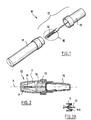
- the device 10 shown in Figures 1 to 4 includes a container 11 containing a supply of cosmetic product such as mascara and an applicator 12 comprising a rod 13 of axis X, provided at one end with an applicator element 14 and at the other end of a gripping element 15 which also constitutes a cap container closure 11.
- a container 11 containing a supply of cosmetic product such as mascara
- an applicator 12 comprising a rod 13 of axis X, provided at one end with an applicator element 14 and at the other end of a gripping element 15 which also constitutes a cap container closure 11.
- the container 11 comprises in the example described a wiping member 16 formed here by a block of open cell foam.
- wipers can be used, for example a flexible lip 16A as illustrated in FIG. 2A, flocked or not.
- the wiper member is arranged so that it flexes or deforms to take the form of the application element when the latter passes through it.
- the container is tightly closed when not in use, providing for example a sealing surface on the gripping member 15 or the rod of the applicator.
- the application element appears under the shape of a comb 14 which has a single row of teeth made in one piece by plastic molding with a relatively wide base 17, of axis Z extending in the extension of the rod 13 of the applicator.
- the rod 13 has a smaller diameter over part of its length that the comb 14, in particular so as not to deform permanently the wiper member 16 (or 16A).
- the comb 14 comprises in the example described two sets of teeth 18a and 18b arranged alternately, the bases 19 of which are non-contiguous and substantially aligned along the Z axis of the base 17.
- the upper parts of the teeth are oriented alternately respectively on either side of a geometric separation surface S, constituted here by a plane extending parallel to the bases 19 of the teeth and containing the axis Z of the base 17.
- the axis Z of the base 17 can be merged with the axis X of the rod 13 or form an angle with it, improving the ergonomics of the applicator.
- the total height of the teeth is preferably between 0.5 mm and 15 mm and more preferably is between 7 and 13 mm approximately.
- the heights of the teeth are not necessarily equal and the height may vary from tooth to tooth.
- the teeth 18a have their free end tilted to the left while the teeth 18b, each located halfway between two teeth 18a, have their free end inclined to the right.
- the total length of a row of consecutive teeth is from preferably between 10 mm and 45 mm approximately, or even between 15 and 28 mm and preferably still between 20 mm and 26 mm.
- the number of teeth per row is preferably between 6 and 50 approximately, or even between 10 and 35 approximately, and more preferably between 15 and 32 approximately.
- Two successive teeth form notches between them allowing the application element to grip the eyelashes during the application of the product to the latter.
- the offset upper parts of the teeth can form cavities allowing to build up product reserves on the application element.
- the base can have various embodiments.
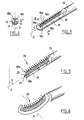
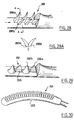
- FIG. 5 shows an application element 20 comprising a narrower base 22 and two sets of teeth 28a and 28b forming a row of consecutive teeth.
- Teeth 28a and 28b consecutive have bases 29 substantially aligned along the Z axis of the base 22 and the upper parts, extending from the bases and going to the free end of the teeth, arranged alternately on both sides of a geometrical surface of separation S, constituted here by a median plane of symmetry for the base 22.
- the upper portion of tooth 28a is located on one side of the separating geometric surface S and the upper portion of the tooth 28b are located on the opposite side of the surface S.
- the width of the base 22 shown in Figure 5 is barely greater the width of the bases 29 of the teeth.
- the base 22 supporting the teeth of the comb may be rectilinear with a Z axis as just described.
- the base can also be curved or extend along a broken line, for example a zigzag line.
- the base can be curved around an axis K substantially perpendicular to the bases of the teeth, as in the case of the comb 30 shown in figure 6.
- the teeth are alternately oriented at their upper part towards the front, i.e. the distal end of the comb, and towards the rear, that is to say towards the applicator rod, in addition to being offset alternately to the right and to the left.
- the base can thus be curved around a non-perpendicular axis at the bases of the teeth.
- the base can also be curved around a substantially parallel axis at the bases of the teeth, as is the case with the comb 40 shown in the figure 7.
- the geometric area of separation on either side of which extend alternately the upper parts of the teeth is a surface cylindrical director consisting of the axis of the base, this director here being a curved line, and of generator parallel to the bases of the teeth, this generator being here perpendicular to the plane of Figure 7.
- the director can generally be a curve or a broken line, for example a zigzag line.
- the geometry of the base is chosen according to the type of makeup and the nature of the product to be applied to the eyelashes.
- teeth of the comb can be produced in multiple ways without this is beyond the scope of the present invention.
- the two sets of alternating teeth may each have teeth having a symmetrical base of revolution or not.
- the base of the teeth may have a circular, polygonal cross section Or other.
- the upper parts of the teeth may have a rounded head or a hook.
- the geometry of the teeth will be chosen according to the nature of the product to be applied to the eyelashes and the type of makeup sought.
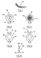
- FIGS. 8 to 11, 17 and 18 show various configurations teeth, the application element being observed along the longitudinal axis of the base.
- FIG. 8 There is shown in Figure 8 in front view along the axis of the base a applicator element 50 essentially in the form of a comb having two series of alternating teeth 51a and 51b, the bases 52 of which are substantially aligned on the base 53.
- Teeth 51a and 51b have generally curved shapes, essentially concave inwards and define a housing 55 therebetween.
- This housing 55 can receive a brush of the twisted core type 56, as shown in figure 9.
- the free ends 54 of the teeth are directed inward but do not not cross when the comb is observed along the longitudinal axis of the base 53.
- the free ends of the teeth may cross, when the comb is observed along the longitudinal axis of the base.
- FIG. 10 shows a comb 60 in which the free ends 67 of the two sets of alternating teeth 61a and 61b intersect when the comb is observed along the axis of the base.
- the free ends of consecutive teeth may also diverge when the comb is observed along the axis of the base.
- FIG. 11 shows a comb 70 in which the free ends 77 of the two sets of alternating teeth 71a and 71b diverge.
- the inclination of the teeth may tend to make tangential contact with eyelashes at the time of application.
- the applicator element 120 shown in FIG. 17 includes alternating teeth 121a and 121b whose free ends 122 are substantially aligned.
- This alignment is done in the example described along a line parallel to that according to which the bases of the teeth are substantially aligned.
- the applicator element 13 () has consecutive teeth 131a and 131b whose free ends 132 are substantially parallel. Thus, they point in the same direction.
- FIG. 26 shows an application element 260 comprising two sets of teeth 261a and 261b forming a row of consecutive teeth.
- the bases of consecutive teeth 261a, 261b are substantially aligned.
- the free ends of the teeth are arranged so that the consecutive teeth alternately have a substantially straight free end and an end free which diverges by deviating from the substantially straight free ends, that is to say the ends of the teeth 261a shown in Figure 26.
- the element may also include a combination of consecutive teeth comprising teeth having divergent free ends and / or free ends converging and / or aligned free ends and / or free ends are crossing and / or parallel free ends, and any combinations of such teeth as shown for example in Figure 27.
- teeth 271a, 271b having free ends substantially aligned at the distal end of the applicator element, then diverging alternately and again having substantially free ends aligned in the vicinity of the proximal end of the applicator element.
- the invention is not limited to an application element comprising a single row of teeth and also applies to application elements comprising several rows of teeth, essentially forming a brush, for example.
- At least one of the rows of teeth has substantially aligned bases and portions of the length of the teeth extending from the hase offset alternately on either side of a geometric separation surface.
- the application element can comprise for example a second row of teeth 91c and 91d opposite a first row of teeth 91a and 91b, as illustrated by the brush 110 very schematically represented in FIG. 12.
- the base may have a polygonal cross section, for example triangular, with a row of teeth extending substantially in the extension on each side. This allows the eyelashes to come into contact with the base to load in product at the time of application.
- FIG. 15 shows a row of teeth 93a, 93b, the bases 90 of which extend substantially in the extension of one side 91 of the base, of triangular section.
- the bases of the rows of teeth may extend radially from the base.
- FIG. 16 shows a brush 100 having a triangular section base and three rows 101 to 103 of teeth, the bases of which are aligned and the portions of the teeth extending from the base are alternately offset on each side of the bases of the teeth.
- the teeth start from the tops of the base, the bases teeth of the different rows being oriented radially.
- the base may have edges on which the teeth are connected, which extend helically, with a constant or variable pitch.
- the base extends substantially in the extension of the applicator rod.
- a proximal end of the base is fixed to a part distal end of the rod, and a distal end of the base constitutes one end free from the applicator.
- FIGS. 13, 14 and 24 show an element of application essentially comb-shaped 80 (fig. 13, 14), 240 (fig. 24) in which the longitudinal axis Z of the applicator element extends substantially perpendicular to the axis X of the rod 84 (fig. 13, 14), 244 (fig. 24) of the applicator, which is flat in the examples illustrated, and could possibly be perforated in its center.
- a lateral surface of the application element or of the base between its two ends connect to the distal end part of the applicator rod.
- the comb 80 comprises two series of alternating teeth 85a and 85b having bases 86 substantially aligned, as can be seen in FIG. 14.
- teeth can be produced by molding plastic material of a in one piece with the base 87 then it can be inserted into a connector presenting in the form of a housing 81 formed at the distal end of the rod 84 of the applicator.
- the housing 81 defines a slot 82, at the front, to allow passage bases 86 of teeth 85a and 85b.
- this slot 82 corresponds substantially to the thickness of the bases 86 of the teeth, so that the comb 80 is retained in the housing 81 by clamping the bases 86 between the opposite edges of the slot 82.
- This assembly allows the comb to be easily made from a plastic material elastomer and the rod 84 in a rigid or semi-rigid plastic material.
- Figures 19 and 20 show various configurations of the application element that can help achieve desired application effects.
- the teeth 191a, 191b can be flocked.
- This flocking can come from the plastic material used to make the teeth.
- the base can also receive flocking.
- the teeth 201a, 201b can present hollow portions 202. These hollow portions preferably extend over at least part of the length of the teeth and at least one opening 202 'on the side of the teeth gives access to this hollow part. These hollow parts can contain product and therefore contribute to the loading of product from the applicator as well only to increase the amount of product deposited on the eyelashes during application.
- FIGS 21 and 22 show alternative embodiments of the invention.
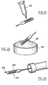
- FIG. 21 represents a set of applications in which the product is contained in a container 210 in the form of a tube.
- This tube is preferably made in a flexible material which allows to distribute the product on the application element when compressed.
- the application set shown in the figure 22 includes a container 220 containing a solid bread of product 225. This solid bread can be moistened and the applicator element moved in contact with the moistened part product to load product.
- the application element can be moistened and moved to the contact with a non-humidified part.
- the rod itself can be used as a handle.
- Figure 23 shows an applicator according to a variant of setting of the invention.
- the applicator shown in this figure has a tip 235 extending from the base 233 of the application element 231.
- the tip 235 can also be loaded with product and serve as an eyeliner or element to be inserted between isolated eyelashes.
- FIG. 24 represents an applicator similar to that described with reference in Figure 13.
- the base 243 is formed in one piece with the structure made by molding with the rod.
- Teeth 241 can also be made in one piece with the base 243 and the rod 244.
- FIG. 25 represents another example of implementation of the invention wherein the base of the application element is removably fixed in a housing forming connector 257, produced in a distal end part of the rod.
- This housing defines a slot in which the base of the application element can be engaged.
- the longitudinal axis of the application element 251, a once fixed in connector 257, extends from the rod substantially in the same direction as the longitudinal axis of the rod.
- Figures 28 and 28A show an example of consecutive teeth on an applicator element 281, in which the bases 289a and 289b are substantially aligned within the meaning of the present invention.
- FIG. 29 represents an example of implementation of the invention in which teeth 292a and 292b have bases 299 having enlarged portions extending in directions substantially perpendicular to the longitudinal axis of the parts of the teeth extending from the bases.
- consecutive teeth have parts extending from the bases teeth extending alternately from opposite sides of the bases of the teeth, that is to say alternately from a left side of the bases and a right side of the bases when the application element is observed along its longitudinal axis.
- FIG. 30 represents an applicator in which the application element 331, including a base 333, is generally flexible, which allows it to deform relative to the rod when applying the product.
- This convex shape causes the adjacent teeth to diverge, allowing thus a relatively large amount of product is lodged between the teeth.
- the applicator of Figure 30 can improve the loading in product when the applicator is extracted through a wiping member, because the latter exerts a force tending to straighten the application element and to bring the teeth towards a central region (towards the mid-length) of the application element.
- the product can be chased between the teeth toward the base, allowing the application member to hold a relatively small amount high product.
- the application element may include a succession of teeth comprising a first and a second series of teeth arranged alternately, the teeth of the first series having a shape different from the teeth of the second series.
- One of the sets of teeth can itself be composed of teeth having different shapes, even different heights.
- the teeth may have a height which varies according to the positioning axial on the application element, for example an increasing, decreasing height, decreasing then increasing or increasing then decreasing, from the front rearward.
- the teeth may have a surface condition making it possible to increase the quantity of product taken care of by the application element; teeth and / or base may thus include capillary grooves or flocking, on all or part of their surface.
- the teeth can be covered with a coating such as varnish or PTFE for example, intended to give them better sliding on the eyelashes or on the contrary, more roughness.
- Slip agents can be incorporated into the plastic used to make the teeth.
- the application element and more particularly the teeth, can also contain assets such as, for example, preservatives, absorbers moisture, metal salts, especially copper salts, magnetic particles, and other suitable similar materials intended for release into the produced when the latter is deposited on the application element.
- assets such as, for example, preservatives, absorbers moisture, metal salts, especially copper salts, magnetic particles, and other suitable similar materials intended for release into the produced when the latter is deposited on the application element.
- products which modify the surface tension of the element application in contact with moisture can be incorporated into the teeth or coated these last.
- Teeth can undergo surface treatment by abrasion, to form for example forks at their free end.
- Teeth can undergo a heat treatment to round for example their tip, even forming a ball at their free end.
- the teeth become so less aggressive towards the eyelashes.
- the application element is preferably produced by injecting material plastic, but alternatively we can use material conformation processes by compression, stamping or bar turning.
- the base may include grooves or reliefs allowing for example to house product.
- the length of a row of teeth consecutive is preferably between approximately 10 mm and approximately 45 mm, and more preferably between about 15 mm and about 28 mm, and more preferably between 20 mm and about 26 mm.
- each tooth is preferably between 0.5 mm and Approximately 15 mm, and more preferably between approximately 7 mm and approximately 13 mm.
- the number of teeth in a consecutive row is preferably understood between 6 and 50, and more preferably between 1 () and 35, and more preferably between 15 and 32 approximately.
Abstract
Description
La présente invention concerne l'application d'un produit, notamment cosmétique, sur les cils ou les sourcils.The present invention relates to the application of a product, in particular cosmetic, on eyelashes or eyebrows.
L'invention a notamment pour objet un nouveau dispositif pour appliquer un produit sur les cils ou les sourcils, comprenant un récipient pour contenir une réserve de produit et un applicateur comprenant un élément d'application ayant au moins une rangée de dents, cette dernière comportant une succession de dents consécutives, chaque dent de cette succession de dents comprenant une base et une portion s'étendant à partir de la base. Ce dispositif est caractérisé par le fait que les bases desdites dents consécutives sont sensiblement alignées et par le fait que les portions s'étendant à partir des bases desdites dents consécutives sont décalées alternativement de part et d'autre d'une surface géométrique de séparation.The invention particularly relates to a new device for applying a product on the eyelashes or the eyebrows, comprising a container for containing a reserve of product and an applicator comprising an application element having at at least one row of teeth, the latter comprising a succession of consecutive teeth, each tooth of this succession of teeth comprising a base and a portion extending from the base. This device is characterized by the fact that the basics of said consecutive teeth are substantially aligned and by the fact that the portions extending from the bases of said consecutive teeth are offset alternately on either side of a geometric separation surface.
L'applicateur selon l'invention comporte de préférence une tige, avec au moins une rangée d'une succession de dents consécutives disposée à une extrémité de la tige. Les dents peuvent être réalisées par moulage de matière plastique.The applicator according to the invention preferably comprises a rod, with at least one row of a succession of consecutive teeth arranged at one end of the stem. The teeth can be produced by plastic molding.
Par « bases sensiblement alignées », il faut comprendre qu'une portion de chacune des bases des dents consécutives est disposée d'un premier côté d'une ligne passant par les bases des dents consécutives, et une autre portion de chacune des bases des dents consécutives est disposée d'un second côté de la ligne précitée, opposé au premier côté, cette ligne étant sensiblement parallèle à un axe longitudinal d'une embase sur laquelle les dents sont disposées. Dans une réalisation particulière, non limitative de l'invention, avec des dents dont les bases sont sensiblement alignées, les dents consécutives sont disposées de telle sorte qu'une ligne droite passe par les centres de chacune des bases des dents consécutives. Ainsi, les centres des bases de trois dents consécutives peuvent se situer sur une même droite.By “substantially aligned bases”, it should be understood that a portion of each of the bases of the consecutive teeth is arranged on a first side of a line passing through the bases of consecutive teeth, and another portion of each of the bases consecutive teeth is arranged on a second side of the aforementioned line, opposite on the first side, this line being substantially parallel to a longitudinal axis of a base on which the teeth are arranged. In a particular realization, not limitation of the invention, with teeth whose bases are substantially aligned, the consecutive teeth are arranged so that a straight line passes through the centers of each of the bases of consecutive teeth. So the centers of the bases of three consecutive teeth may lie on the same straight line.
Le fait d'avoir des bases sensiblement alignées et des parties s'étendant à partir des hases alternativement décalées procure des avantages.Having substantially aligned bases and portions extending Using alternately offset hases provides advantages.
En particulier, en jouant sur la géométrie des dents et leur écartement il est possible de constituer des cavités plus ou moins importantes entre les dents, cavités qui peuvent se charger de produit au moment de l'application.In particular, by playing on the geometry of the teeth and their spacing it it is possible to form more or less large cavities between the teeth, cavities who can load the product at the time of application.
Il est ainsi possible de réaliser un élément d'application capable de se charger avec une quantité substantielle de produit, sans pour autant que l'élément d'application perde sa capacité à agripper les cils.It is thus possible to produce an application element capable of load with a substantial amount of product, without the element application loses its ability to grip the eyelashes.
Les dents peuvent être réalisées avec un faible écartement à leur base, de manière à ce que les cils puissent être saisis efficacement entre deux dents consécutives, tout en ayant un écartement plus important entre leurs extrémités libres, favorisant l'engagement des cils entre les dents et la constitution de réserves de produit sur l'élément d'application.The teeth can be made with a small gap at their base, of so that the eyelashes can be effectively gripped between two consecutive teeth, while having a greater spacing between their free ends, favoring the engagement of the eyelashes between the teeth and the constitution of product reserves on the application element.
La disposition géométrique des dents permet également à des fibres de petites dimensions, éventuellement contenues dans le produit, de s'aligner de manière à être sensiblement parallèles les unes aux autres lorsque le produit est appliqué, ou lorsque les dents sont engagées à travers un organe d'essorage, ou les deux. Cet alignement résulte d'un effet d'entonnoir entre deux dents consécutives.The geometrical arrangement of the teeth also allows fibers to small dimensions, possibly contained in the product, to align so to be substantially parallel to each other when the product is applied, or when the teeth are engaged through a wiping member, or both. This alignment results from a funneling effect between two consecutive teeth.
L'écartement entre les bases de deux dents consécutives est de préférence inférieur ou égal à 0,4 mm.The spacing between the bases of two consecutive teeth is preferably less than or equal to 0.4 mm.
De préférence, la surface géométrique de séparation passe par les centres des bases des dents.Preferably, the geometric separation surface passes through the centers of the bases of the teeth.
De préférence encore, l'élément d'application comporte une embase.More preferably, the application element comprises a base.
Dans un mode de réalisation particulier, les dents sont réalisées par moulage de matière plastique d'un seul tenant avec l'embase.In a particular embodiment, the teeth are produced by plastic molding in one piece with the base.
L'embase peut être fixée sur la tige de l'applicateur et l'embase peut avoir son axe parallèle ou non à celui de la tige de l'applicateur.The base can be attached to the applicator rod and the base can have its axis parallel or not to that of the applicator rod.
L'embase peut être fixée de manière amovible sur la tige de l'applicateur.The base can be removably attached to the stem of the applicator.
La surface géométrique de séparation peut être un plan, de préférence un plan de symétrie pour l'embase.The geometric separation surface can be a plane, preferably a plane of symmetry for the base.
De préférence, la surface géométrique de séparation est un plan de joint pour le moulage des dents et/ou de l'élément d'application.Preferably, the geometric separation surface is a joint plane for molding the teeth and / or the application element.
La surface géométrique de séparation peut être non plane, par exemple vrillée.The geometric separation surface can be non-planar, for example twisted.
La surface géométrique de séparation peut ainsi être une surface hélicoïdale ou une surface courbe, par exemple.The geometric separation surface can thus be a helical surface or a curved surface, for example.
La hauteur de la base des dents peut être supérieure ou égale à 0,2 mm, par exemple.The height of the base of the teeth can be greater than or equal to 0.2 mm, for example.
La tige de l'applicateur peut être plate ou sensiblement cylindrique ou présenter d'autres configurations encore, selon les effets désirés et l'ergonomie recherchée.The applicator stem may be flat or substantially cylindrical or present yet other configurations, depending on the desired effects and the desired ergonomics.
La tige peut comporter à son extrémité distale un connecteur dans lequel l'embase peut être engagée de manière amovible.The rod may have a connector at its distal end in which the base can be engaged in a removable manner.
Dans une réalisation préférée, le connecteur comporte un logement définissant une fente agencée pour recevoir l'embase.In a preferred embodiment, the connector comprises a housing defining a slot arranged to receive the base.
Le logement peut avoir un axe longitudinal qui est parallèle à l'axe de la tige ou faire un angle avec celui-ci, l'axe longitudinal du logement étant par exemple sensiblement perpendiculaire à l'axe longitudinal de la tige.The housing may have a longitudinal axis which is parallel to the axis of the rod or make an angle with it, the longitudinal axis of the housing being for example substantially perpendicular to the longitudinal axis of the rod.
Dans une réalisation particulière, la fente qui reçoit l'embase reçoit également les bases des dents, et la fente peut venir en prise sur les bases des dents.In a particular embodiment, the slot which receives the base also receives the bases of the teeth, and the slot may engage the bases of the teeth.
L'embase peut également être réalisée par moulage de matière plastique d'un seul tenant avec la tige de l'applicateur.The base can also be produced by plastic molding in one piece with the applicator rod.
L'élément d'application peut être réalisé par moulage de matière plastique d'un seul tenant avec la tige de l'applicateur et avec un organe d'étanchéité destiné à assurer une fermeture étanche du récipient en l'absence d'utilisation, cet organe d'étanchéité pouvant présenter une surface conformée pour s'ajuster de manière étanche dans un col du récipient.The application element can be produced by plastic molding in one piece with the applicator rod and with a sealing member intended to ensure a tight closure of the container in the absence of use, this sealing member which may have a shaped surface to adjust so waterproof in a container neck.
Dans une réalisation particulière, le récipient comporte un organe d'essorage agencé pour retirer l'excès de produit des dents lorsque l'applicateur est retiré du récipient.In a particular embodiment, the container comprises a wiping member arranged to remove excess product from the teeth when the applicator is removed from the container.
Cet organe d'essorage est de préférence déformable.This wiper member is preferably deformable.
De préférence, un capuchon de fermeture est disposé à une extrémité de l'applicateur opposée à l'extrémité comprenant les dents, ce capuchon de fermeture étant destiné à femer le récipient contenant le produit à appliquer.Preferably, a closure cap is disposed at one end of the applicator opposite the end comprising the teeth, this closure cap being intended to close the container containing the product to be applied.
Ce capuchon de fermeture peut être muni d'un moyen d'étanchéité pour fermer de manière étanche le récipient. This closure cap may be provided with a sealing means for seal the container.
Lorsque l'applicateur est observé dans l'axe longitudinal d'une portion de l'élément d'application sur laquelle sont disposées les dents, au moins deux dents consécutives peuvent avoir des extrémités libres qui divergent, convergent, se croisent ou sont sensiblement parallèles.When the applicator is observed in the longitudinal axis of a portion of the application element on which the teeth are arranged, at least two teeth consecutive may have free ends that diverge, converge, intersect or are substantially parallel.
Lorsque l'applicateur est observé selon l'axe longitudinal d'une portion de l'élément d'application sur laquelle sont disposées les dents, une dent sur au moins deux dents consécutives peut avoir une extrémité libre qui diverge en s'écartant de l'extrémité libre de l'autre dent, cette autre dent pouvant avoir une extrémité libre qui est sensiblement rectiligne.When the applicator is observed along the longitudinal axis of a portion of the application element on which the teeth are arranged, one tooth on at least two consecutive teeth may have a free end which diverges away from the free end of the other tooth, this other tooth possibly having a free end which is substantially straight.
Lorsque l'élément d'application est observé dans son axe, au moins deux dents consécutives, de préférence trois, peuvent avoir des extrémités libres qui sont sensiblement alignées.When the application element is observed in its axis, at least two consecutive teeth, preferably three, may have free ends which are substantially aligned.
L'élément d'application peut comporter des dents ayant des extrémités libres orientées vers une extrémité proximale de l'applicateur, disposées en alternance avec des dents ayant des extrémités libres orientées vers une extrémité distale de l'applicateur.The applicator element may include teeth having free ends oriented towards a proximal end of the applicator, arranged alternately with teeth having free ends oriented towards a distal end of the applicator.
Les dents peuvent ménager entre elles un logement d'axe sensiblement parallèle à celui de l'embase. Ce logement peut permettre de recevoir un élément d'application intérieur tel qu'une brosse du type à âme torsadée.The teeth can form between them a housing of substantially axis parallel to that of the base. This housing can accommodate an element for interior application such as a brush of the twisted core type.
L'élément d'application peut ne comporter qu'une seule rangée de dents et constituer un peigne.The applicator element may have only one row of teeth and make up a comb.
L'élément d'application peut aussi comporter plusieurs rangées de dents disposées à des positions angulaires différentes autour de l'applicateur et constituer une brosse.The applicator element can also have several rows of teeth arranged at different angular positions around the applicator and constitute a brush.
L'élément d'application peut comporter par exemple une deuxième rangée de dents à l'opposé de la première.The application element can comprise for example a second row of teeth opposite the first.
L'élément d'application peut aussi comporter, par exemple, une embase de section transversale polygonale ou non. Au moins une rangée de dents s'étend de préférence sensiblement dans le prolongement d'un côté de l'embase dans le cas d'une section polygonale. Dans le cas d'une section non polygonale, par exemple circulaire ou elliptique, les bases se raccordent de préférence sensiblement tangentiellement à l'embase. Un élément d'application ayant une telle configuration permet d'utiliser l'embase pour appliquer le produit et le contact des cils avec les dents peut s'effectuer de manière progressive. Un élément d'application ayant cette structure peut permettre encore de bien allonger et recourber les cils.The application element can also include, for example, a base of polygonal cross section or not. At least one row of teeth extends from preferably substantially in the extension of one side of the base in the case of a polygonal section. In the case of a non-polygonal section, for example circular or elliptical, the bases preferably connect substantially tangentially at the base. An application element having such a configuration allows use the base to apply the product and the contact of the eyelashes with the teeth can be done gradually. An application element with this structure can still allow to lengthen and curl the eyelashes.
L'élément d'application peut être plus flexible que la tige.The application element can be more flexible than the rod.
L'élément d'application peut être réalisé par exemple dans une matière plastique plus souple que celle utilisée pour fabriquer la tige de l'applicateur. On peut ainsi obtenir plus de confort à l'utilisation.The application element can be made, for example, from a plastic material softer than that used to make the applicator stem. We can thus get more comfort in use.
En variante, la tige de l'applicateur peut être réalisée dans une matière plastique moins dure que celle servant à réaliser l'élément d'application. On peut ainsi utiliser pour des raisons de fabrication par exemple un matériau relativement dur pour réaliser l'élément d'application et compenser la dureté de l'élément d'application au moment de l'application par la souplesse de la tige.Alternatively, the applicator rod can be made of a plastic material less hard than that used to make the application element. We can thus use for manufacturing reasons for example a relatively hard material to make the application element and compensate for the element's hardness of application at the time of application by the flexibility of the rod.
Les dents peuvent également être réalisées dans une matière différente de celle utilisée pour réaliser l'embase.The teeth can also be made of a material different from that used to make the base.
La hauteur des dents peut être variable.The height of the teeth can be variable.
De préférence, la hauteur des dents est comprise entre 0,5 et 15 mm environ, et de préférence encore entre 7 et 13 mm environ.Preferably, the height of the teeth is between 0.5 and 15 mm approximately, and more preferably between 7 and 13 mm approximately.
L'invention a encore pour objet un applicateur pour appliquer un produit sur les cils ou les sourcils comprenant une tige et une embase disposée à une extrémité de la tige. Cet applicateur comporte en outre au moins une rangée de dents ayant des bases disposées sur l'embase et des portions s'étendant à partir des bases. Les bases de dents consécutives sont sensiblement alignées et les portions s'étendant à partir des bases des dents consécutives sont disposées de part et d'autre d'une surface géométrique de séparation.The invention also relates to an applicator for applying a product to eyelashes or eyebrows comprising a rod and a base disposed at one end of the stem. This applicator further comprises at least one row of teeth having bases arranged on the base and portions extending from the bases. The basics of consecutive teeth are substantially aligned and the portions extending from bases of consecutive teeth are arranged on either side of a geometric surface of seperation.
La largeur de l'embase est de préférence supérieure à la largeur des bases.The width of the base is preferably greater than the width of the bases.
Une seconde rangée de dents peut également être disposée sur l'embase. Cette seconde rangée de dents peut être disposée de telle sorte que les rangées soient dirigées dans des directions sensiblement opposées.A second row of teeth can also be arranged on the base. This second row of teeth can be arranged so that the rows are directed in substantially opposite directions.
Les portions s'étendant à partir des bases de dents consécutives peuvent diverger en s'écartant l'une de l'autre. Ces portions divergentes peuvent se trouver à proximité des bases des dents.The portions extending from the bases of consecutive teeth may diverge moving away from each other. These divergent portions can be found at near the bases of the teeth.
Les dents peuvent avoir différentes longueurs et les bases des dents peuvent être soit en contact, soit espacées les unes des autres.The teeth can have different lengths and the bases of the teeth can be either in contact or spaced from each other.
Les dents peuvent être disposées sur l'embase de manière non symétrique
par rapport à une ligne selon laquelle les bases sont alignées.The teeth may be arranged on the base in an asymmetrical manner
relative to a line along which the bases are aligned.
L'embase peut comporter deux extrémités, l'une desquelles peut être fixée à une partie d'extrémité distale de la tige.The base can have two ends, one of which can be fixed to a distal end portion of the stem.
En variante, l'embase peut être fixée à une portion d'extrémité distale de la tige le long d'une partie située entre ses extrémités.Alternatively, the base can be fixed to a distal end portion of the rod along a part located between its ends.
Au moins l'une des dents peut comporter une portion creuse, s'étendant de préférence suivant la longueur de la dent. De préférence, au moins un côté de la dent présente alors une ouverture donnant accès à cette portion creuse.At least one of the teeth may have a hollow portion, extending preferably according to the length of the tooth. Preferably, at least one side of the tooth then has an opening giving access to this hollow portion.
L'une au moins des dents peut être floquée.At least one of the teeth can be flocked.
L'applicateur peut faire partie d'un système comprenant un récipient.The applicator can be part of a system comprising a container.
Ce récipient peut avoir un organe d'essorage.This container may have a wringing member.
De préférence, l'organe d'essorage est déformable, et celui-ci peut comporter un bloc d'une mousse à cellules ouvertes ou une lèvre en élastomère, ou d'autres organes similaires appropriés.Preferably, the wiping member is deformable, and this may include a block of open cell foam or an elastomer lip, or others similar appropriate bodies.
L'invention a encore pour objet un applicateur comprenant une tige et une embase à une extrémité de la tige. Au moins une rangée de dents comprenant des bases est disposée sur l'embase et les bases de dents consécutives de cette rangée sont sensiblement alignées le long d'un plan passant par les bases des dents consécutives, ces dernières comprenant des portions s'étendant à partir de leur base alternativement décalées de chaque côté du plan d'alignement.The invention also relates to an applicator comprising a rod and a base at one end of the rod. At least one row of teeth comprising bases is arranged on the base and the bases of consecutive teeth of this row are substantially aligned along a plane passing through the bases of consecutive teeth, the latter comprising portions extending alternately from their base offset on each side of the alignment plane.
L'invention a encore pour objet un procédé pour appliquer un produit sur les cils au moyen d'un applicateur tel que défini plus haut. Ce procédé comporte les étapes consistant à charger avec du produit au moins une partie des dents et à amener au moins une partie des dents au contact des cils ou des sourcils, de telle sorte que le produit se dépose sur les cils ou les sourcils. Le chargement en produit peut se faire en insérant l'applicateur ou une portion de celui-ci dans un récipient contenant le produit puis en retirant l'applicateur du récipient et en essuyant l'excès de produit qui s'est déposé sur les dents. Le chargement en produit peut également se faire en distribuant le produit à partir du récipient sur les dents ou en amenant ces dernières au contact d'un pain de produit solide, éventuellement humidifié.The invention also relates to a method for applying a product to the eyelashes by means of an applicator as defined above. This process includes the steps of loading with product at least part of the teeth and bringing at least part of the teeth in contact with the eyelashes or eyebrows, so that the product is deposited on the eyelashes or eyebrows. Product loading can be done by inserting the applicator or a portion of it into a container containing the product then removing the applicator from the container and wiping off the excess product that settled on the teeth. Product loading can also be done by distributing the product from the container on the teeth or by bringing them to the contact with a solid product, possibly moistened.
Dans ce dernier cas, le produit peut être humidifié avant d'amener les dents à son contact ou en variante le produit peut être déposé sur les dents et humidifié ensuite.In the latter case, the product can be moistened before bringing the teeth on contact or alternatively the product can be placed on the teeth and moistened then.
De préférence, le produit qui est appliqué est du mascara. Si ce mascara comprend des fibres, le procédé comprend en outre l'étape consistant à orienter les fibres avec les dents, de telle sorte que les fibres soient sensiblement parallèles aux cils lorsque le produit est appliqué.Preferably, the product which is applied is mascara. If this mascara comprises fibers, the method further comprises the step of orienting the fibers with the teeth, so that the fibers are substantially parallel to the eyelashes when the product is applied.
Lorsque l'applicateur comporte une embase sur laquelle les dents sont disposées et une tige, et que l'embase peut être fixée de manière amovible sur la tige, le procédé peut aussi comporter l'étape consistant à fixer l'embase sur la tige. Cela permet à l'applicateur de recevoir des embases interchangeables ayant différentes configurations de dents.When the applicator has a base on which the teeth are arranged and a rod, and that the base can be removably attached to the rod, the method can also include the step of fixing the base on the rod. That allows the applicator to receive interchangeable bases having different tooth configurations.
Ainsi, l'utilisateur peut choisir parmi plusieurs configurations de dents celle permettant d'obtenir l'effet souhaité.So the user can choose from several tooth configurations that allowing to obtain the desired effect.
L'applicateur peut être utilisé pour appliquer un produit cosmétique, de préférence du mascara, sur les cils ou les sourcils. Cependant, d'autres produits peuvent être appliqués et l'applicateur selon la présente invention peut également être utilisé pour peigner les cils ou les sourcils, par exemple.The applicator can be used to apply a cosmetic product, preferably mascara, on eyelashes or eyebrows. However, other products may be applied and the applicator according to the present invention can also be used to comb eyelashes or eyebrows, for example.
D'autres caractéristiques et avantages de la présente invention ressortiront à la lecture de la description détaillée qui va suivre, d'exemples de réalisation non limitatifs de l'invention, et à l'examen du dessin annexé, sur lequel :
- la figure 1 est une vue schématique en perspective d'un dispositif conforme à un premier exemple de mise en oeuvre de l'invention,
- la figure 2 est une coupe axiale schématique représentant l'applicateur rentré dans le récipient,
- la figure 2 est une coupe axiale partielle représentant une variante d'organe d'essorage,
- la figure 3 est une vue à échelle agrandie du détail III de la figure 1.
- la figure 4 est une coupe schématique selon le trait de coupe IV-IV de la figure 3,
- les figures 5 à 7 représentent des variantes de réalisation de l'élément d'application,
- les figures 8 à 11, 17 et 18 sont des vues selon l'axe longitudinal de l'élément d'application, illustrant différentes configurations de dents,
- la figure 12 représente un élément d'application ayant une deuxième rangée de dents à l'opposé de la première,
- la figure 13 représente une variante de réalisation dans laquelle l'axe de l'embase est orienté perpendiculairement à l'axe de la tige de l'applicateur,
- la figure 14 illustre le montage de l'embase dans un logement de la tige de l'applicateur,
- la figure 15 représente partiellement un élément d'application ayant une embase de section triangulaire avec une rangée de dents dans le prolongement d'un côté,
- la figure 16 représente une brosse ayant trois rangées de dents disposées en étoile,
- la figure 19 est une vue de l'embase, selon l'axe longitudinal de l'élément d'application, et de deux dents consécutives floquées, conformément à un autre exemple de mise en oeuvre de l'invention,
- la figure 20 est une vue en perspective, partielle, d'une série de trois dents consécutives creuses, conformément à un autre exemple de mise en oeuvre de l'invention,
- la figure 21 est une vue en perspective d'un exemple de réalisation dans lequel le produit est déposé sur l'élément d'application à partir d'un tube flexible,
- la figure 22 est une vue en perspective d'un autre exemple de mise en oeuvre de l'invention dans lequel le produit destiné à être appliqué se présente sous la forme d'un pain solide ou d'une poudre,
- la figure 23 est une vue schématique en perspective d'un applicateur conforme à un autre exemple de mise en oeuvre de l'invention, dans lequel l'extrémité distale de l'élément d'application comporte une pointe sensiblement effilée,
- la figure 24 est une vue en perspective d'un applicateur ayant,une configuration similaire à celle de l'applicateur de la figure 13, dans lequel l'embase de l'élément d'application est réalisée d'un seul tenant avec la tige,
- la figure 25 est une vue partielle en perspective d'un applicateur dans lequel l'élément d'application est fixé de manière amovible sur une partie d'extrémité distale de la tige, conformément à un autre exemple de mise en oeuvre de l'invention,
- la figure 26 est une vue partielle en perspective d'un applicateur ayant des dents consécutives dont une sur deux est rectiligne et l'autre s'écarte des dents adjacentes,
- la figure 27 est une vue partielle en perspective d'un applicateur ayant des dents consécutives dont les extrémités libres sont sensiblement alignées, des dents consécutives dont les extrémités libres se croisent et des dents consécutives ayant à nouveau des extrémités libres sensiblement parallèles,
- la figure 28 est une vue partielle de dessus, schématique, d'un applicateur ayant des dents consécutives avec des bases sensiblement alignées et des portions s'étendant à partir des bases divergeant les unes des autres,
- la figure 28A est une coupe partielle selon le trait de coupe A-A de la figure 28,
- la figure 29 est une vue partielle en perspective d'un applicateur ayant des dents consécutives avec des bases sensiblement alignées, conformément à un autre exemple de mise en oeuvre de l'invention, et
- la figure 30 est une vue partielle de côté d'un applicateur ayant des dents de différentes hauteurs et dans lequel l'embase est flexible.
- FIG. 1 is a schematic perspective view of a device according to a first example of implementation of the invention,
- FIG. 2 is a schematic axial section showing the applicator tucked into the container,
- FIG. 2 is a partial axial section showing a variant of a wiper member,
- FIG. 3 is an enlarged view of detail III of FIG. 1.
- FIG. 4 is a schematic section along the section line IV-IV of FIG. 3,
- FIGS. 5 to 7 represent alternative embodiments of the application element,
- FIGS. 8 to 11, 17 and 18 are views along the longitudinal axis of the application element, illustrating different configurations of teeth,
- FIG. 12 represents an application element having a second row of teeth opposite the first,
- FIG. 13 represents an alternative embodiment in which the axis of the base is oriented perpendicular to the axis of the stem of the applicator,
- FIG. 14 illustrates the mounting of the base in a housing of the stem of the applicator,
- FIG. 15 partially represents an application element having a base of triangular section with a row of teeth in the extension of one side,
- FIG. 16 represents a brush having three rows of teeth arranged in a star,
- FIG. 19 is a view of the base, along the longitudinal axis of the application element, and of two flocked consecutive teeth, according to another example of implementation of the invention,
- FIG. 20 is a partial perspective view of a series of three consecutive hollow teeth, in accordance with another example of implementation of the invention,
- FIG. 21 is a perspective view of an exemplary embodiment in which the product is deposited on the application element from a flexible tube,
- FIG. 22 is a perspective view of another example of implementation of the invention in which the product intended to be applied is in the form of a solid bread or a powder,
- FIG. 23 is a schematic perspective view of an applicator according to another example of implementation of the invention, in which the distal end of the application element has a substantially tapered tip,
- FIG. 24 is a perspective view of an applicator having a configuration similar to that of the applicator of FIG. 13, in which the base of the application element is produced in one piece with the rod ,
- FIG. 25 is a partial perspective view of an applicator in which the application element is removably fixed to a distal end part of the rod, in accordance with another example of implementation of the invention ,
- FIG. 26 is a partial perspective view of an applicator having consecutive teeth of which one in two is straight and the other deviates from the adjacent teeth,
- FIG. 27 is a partial perspective view of an applicator having consecutive teeth whose free ends are substantially aligned, consecutive teeth whose free ends intersect and consecutive teeth again having substantially parallel free ends,
- FIG. 28 is a partial schematic view from above of an applicator having consecutive teeth with bases substantially aligned and portions extending from the bases diverging from each other,
- FIG. 28A is a partial section along the section line AA in FIG. 28,
- FIG. 29 is a partial perspective view of an applicator having consecutive teeth with bases substantially aligned, in accordance with another example of implementation of the invention, and
- Figure 30 is a partial side view of an applicator having teeth of different heights and in which the base is flexible.
Le dispositif 10 représenté sur les figures 1 à 4 comporte un récipient 11
contenant une réserve de produit cosmétique tel que du mascara et un applicateur 12
comportant une tige 13 d'axe X, munie à une extrémité d'un élément d'application 14
et à l'autre extrémité d'un élément de préhension 15 qui constitue également un capuchon
de fermeture de récipient 11.The
Le récipient 11 comporte dans l'exemple décrit un organe d'essorage 16
constitué ici par un bloc de mousse à cellules ouvertes. The
D'autres types d'organes d'essorage peuvent être utilisés, par exemple une
lèvre souple 16A comme illustré sur la figure 2A, floquée ou non.Other types of wipers can be used, for example a
L'organe d'essorage est agencé de telle sorte qu'il fléchit ou se déforme pour prendre la forme de l'élément d'application lorsque celui-ci le traverse.The wiper member is arranged so that it flexes or deforms to take the form of the application element when the latter passes through it.
Le récipient est fermé de façon étanche en l'absence d'utilisation, en prévoyant
par exemple une surface d'étanchéité sur l'organe de préhension 15 ou la tige
de l'applicateur.The container is tightly closed when not in use, providing
for example a sealing surface on the gripping
Dans l'exemple représenté, l'élément d'application se présente sous la
forme d'un peigne 14 qui comporte une seule rangée de dents réalisées d'un seul tenant
par moulage de matière plastique avec une embase 17 relativement large, d'axe
Z s'étendant dans le prolongement de la tige 13 de l'applicateur.In the example shown, the application element appears under the
shape of a
La tige 13 présente sur une partie de sa longueur un moindre diamètre
que le peigne 14, notamment afin de ne pas déformer de manière permanente
l'organe d'essorage 16 (ou 16A).The
Le peigne 14 comporte dans l'exemple décrit deux séries de dents 18a et
18b disposées en alternance, dont les bases 19 sont non jointives et sensiblement alignées
suivant l'axe Z de l'embase 17.The
Les parties supérieures des dents sont orientées alternativement respectivement
de part et d'autre d'une surface géométrique de séparation S, constituée ici
par un plan s'étendant parallèlement aux bases 19 des dents et contenant l'axe Z de
l'embase 17.The upper parts of the teeth are oriented alternately respectively
on either side of a geometric separation surface S, constituted here
by a plane extending parallel to the
L'axe Z de l'embase 17 peut être confondu avec l'axe X de la tige 13 ou
former un angle avec celui-ci, permettant d'améliorer l'ergonomie de l'applicateur.The axis Z of the base 17 can be merged with the axis X of the
La hauteur totale des dents est de préférence comprise entre 0,5 mm et 15 mm et de préférence encore est comprise entre 7 et 13 mm environ.The total height of the teeth is preferably between 0.5 mm and 15 mm and more preferably is between 7 and 13 mm approximately.
Les hauteurs des dents ne sont pas nécessairement égales et la hauteur peut varier d'une dent à l'autre.The heights of the teeth are not necessarily equal and the height may vary from tooth to tooth.
Comme on peut le voir sur la figure 4, les dents 18a ont leur extrémité libre
inclinée vers la gauche tandis que les dents 18b, situées chacune à mi-distance
entre deux dents 18a, ont leur extrémité libre inclinée vers la droite.As can be seen in Figure 4, the
Grâce à cette disposition des dents 18a et 18b sur le peigne 14, on peut
avoir un espacement entre les bases 19 des dents nul ou très faible, par exemple inférieur
ou égal à 0,4 mm.Thanks to this arrangement of the
La longueur totale d'une rangée de dents consécutives est comprise de préférence entre 10 mm et 45 mm environ, voire entre 15 et 28 mm et de préférence encore entre 20 mm et 26 mm.The total length of a row of consecutive teeth is from preferably between 10 mm and 45 mm approximately, or even between 15 and 28 mm and preferably still between 20 mm and 26 mm.
Le nombre de dents par rangée est compris de préférence entre 6 et 50 environ, voire entre 10 et 35 environ, et de préférence encore entre 15 et 32 environ.The number of teeth per row is preferably between 6 and 50 approximately, or even between 10 and 35 approximately, and more preferably between 15 and 32 approximately.
Deux dents successives forment entre elles des échancrures permettant à l'élément d'application d'agripper les cils durant l'application du produit sur ces derniers.Two successive teeth form notches between them allowing the application element to grip the eyelashes during the application of the product to the latter.
Cela peut entrainer une amélioration dans l'allongement et le recourbement des cils.This can lead to improvement in lengthening and bending Eyelash.
Les parties supérieures décalées des dents peuvent former entre elles des cavités permettant de constituer des réserves de produit sur l'élément d'application.The offset upper parts of the teeth can form cavities allowing to build up product reserves on the application element.
Cela peut améliorer la manière dont l'élément d'application se charge en produit, de sorte que d'avantage de produit peut être appliqué avant qu'il soit nécessaire de recharger l'applicateur.This can improve the way the application element loads by product, so more product can be applied before it is needed to recharge the applicator.
Chacun de ces effets, à savoir l'effet d'agripement des cils et l'effet de chargement en produit, contribue à l'obtention d'un maquillage de qualité.Each of these effects, namely the eyelash grip effect and the loading of product, contributes to obtaining quality makeup.
L'embase peut présenter diverses formes de réalisation.The base can have various embodiments.
A titre d'exemple, on a représenté sur la figure 5 un élément d'application
20 comportant une embase 22 plus étroite et deux séries de dents 28a et 28b formant
une rangée de dents consécutives.By way of example, FIG. 5 shows an
Les dents 28a et 28b consécutives ont des bases 29 sensiblement alignées
suivant l'axe Z de l'embase 22 et des parties supérieures, s'étendant à partir des bases
et allant jusqu'à l'extrémité libre des dents, disposées alternativement de part et d'autre
d'une surface géométrique de séparation S, constituée ici par un plan médian de
symétrie pour l'embase 22.
Autrement dit, la portion supérieure de la dent 28a se situe d'un côté de
la surface de géométrique de séparation S et la portion supérieure de la dent 28b se
situe du côté opposé de la surface S. In other words, the upper portion of
La largeur de l'embase 22 représentée sur la figure 5 est à peine supérieure
à la largeur des bases 29 des dents.The width of the base 22 shown in Figure 5 is barely greater
the width of the
L'embase 22 supportant les dents du peigne peut être rectiligne d'axe Z comme cela vient d'être décrit.The base 22 supporting the teeth of the comb may be rectilinear with a Z axis as just described.
L'embase peut aussi être courbe ou s'étendre suivant une ligne brisée, par exemple une ligne en zigzag.The base can also be curved or extend along a broken line, for example a zigzag line.
En particulier, l'embase peut être incurvée autour d'un axe K sensiblement
perpendiculaire aux bases des dents, comme c'est le cas du peigne 30 représenté
sur la figure 6.In particular, the base can be curved around an axis K substantially
perpendicular to the bases of the teeth, as in the case of the
En outre, sur cette figure 6, les dents sont alternativement orientées à leur partie supérieure vers l'avant, c'est à dire l'extrémité distale du peigne, et vers l'arrière, c'est à dire vers la tige de l'applicateur, en plus d'être décalées alternativement vers la droite et vers la gauche.In addition, in this figure 6, the teeth are alternately oriented at their upper part towards the front, i.e. the distal end of the comb, and towards the rear, that is to say towards the applicator rod, in addition to being offset alternately to the right and to the left.
L'embase peut ainsi être incurvée autour d'un axe non perpendiculaire aux bases des dents.The base can thus be curved around a non-perpendicular axis at the bases of the teeth.
L'embase peut également être incurvée autour d'un axe sensiblement parallèle
aux bases des dents, comme c'est le cas du peigne 40 représenté sur la figure
7.The base can also be curved around a substantially parallel axis
at the bases of the teeth, as is the case with the
Sur cette figure, la surface géométrique de séparation de part et d'autre de laquelle s'étendent alternativement les parties supérieures des dents est une surface cylindrique de directrice constituée par l'axe de l'embase, cette directrice étant ici une ligne courbe, et de génératrice parallèle aux bases des dents, cette génératrice étant ici perpendiculaire au plan de la figure 7.In this figure, the geometric area of separation on either side of which extend alternately the upper parts of the teeth is a surface cylindrical director consisting of the axis of the base, this director here being a curved line, and of generator parallel to the bases of the teeth, this generator being here perpendicular to the plane of Figure 7.
Lorsque la surface géométrique de séparation est cylindrique, la directrice peut d'une manière générale être une courbe ou une ligne brisée, par exemple une ligne en zigzag.When the geometric separation surface is cylindrical, the director can generally be a curve or a broken line, for example a zigzag line.
La géométrie de l'embase est choisie en fonction du type de maquillage et de la nature du produit à appliquer sur les cils.The geometry of the base is chosen according to the type of makeup and the nature of the product to be applied to the eyelashes.
Les dents du peigne peuvent être réalisées de multiples manières sans que l'on sorte du cadre de la présente invention.The teeth of the comb can be produced in multiple ways without this is beyond the scope of the present invention.
En particulier, les deux séries de dents alternées peuvent comporter chacune des dents ayant une base symétrique de révolution ou non.In particular, the two sets of alternating teeth may each have teeth having a symmetrical base of revolution or not.
La base des dents peut présenter une section transversale circulaire, polygonale ou autre.The base of the teeth may have a circular, polygonal cross section Or other.
Les parties supérieures des dents peuvent comporter une tête arrondie ou un crochet.The upper parts of the teeth may have a rounded head or a hook.
D'une manière générale, la géométrie des dents sera choisie en fonction de la nature du produit à appliquer sur les cils et du type de maquillage recherché.In general, the geometry of the teeth will be chosen according to the nature of the product to be applied to the eyelashes and the type of makeup sought.
On a représenté sur les figures 8 à 11, 17 et 18, diverses configurations de dents, l'élément d'application étant observé selon l'axe longitudinal de l'embase.FIGS. 8 to 11, 17 and 18 show various configurations teeth, the application element being observed along the longitudinal axis of the base.
On a représenté sur la figure 8 en vue de face selon l'axe de l'embase un
élément d'application 50 essentiellement en forme de peigne ayant deux séries de
dents alternées 51a et 51b, dont les bases 52 sont sensiblement alignées sur l'embase
53.There is shown in Figure 8 in front view along the axis of the base a
Les dents 51a et 51b présentent des formes générales incurvées, essentiellement
concaves vers l'intérieur et définissent un logement 55 entre elles.
Ce logement 55 peut recevoir une brosse de type à âme torsadée 56,
comme illustré sur la figure 9.This
Les extrémités libres 54 des dents sont dirigées vers l'intérieur mais ne se
croisent pas lorsque le peigne est observé selon l'axe longitudinal de l'embase 53.The free ends 54 of the teeth are directed inward but do not
not cross when the comb is observed along the longitudinal axis of the
En variante, les extrémités libres des dents peuvent se croiser, lorsque le peigne est observé selon l'axe longitudinal de l'embase.Alternatively, the free ends of the teeth may cross, when the comb is observed along the longitudinal axis of the base.
A titre d'exemple, on a représenté sur la figure 10 un peigne 60 dans lequel
les extrémités libres 67 des deux séries de dents alternées 61a et 61b se croisent
lorsque le peigne est observé selon l'axe de l'embase.By way of example, FIG. 10 shows a
Les extrémités libres des dents consécutives peuvent également diverger lorsque le peigne est observé selon l'axe de l'embase.The free ends of consecutive teeth may also diverge when the comb is observed along the axis of the base.
A titre d'exemple, on a représenté sur la figure 11 un peigne 70 dans lequel
les extrémités libres 77 des deux séries de dents alternées 71a et 71b divergent.By way of example, FIG. 11 shows a
L'inclinaison des dents peut tendre à réaliser un contact tangentiel avec les cils au moment de l'application.The inclination of the teeth may tend to make tangential contact with eyelashes at the time of application.
L'élément d'application 120 représenté sur la figure 17 comporte des
dents alternées 121a et 121b dont les extrémités libres 122 sont sensiblement alignées.The
Cet alignement se fait dans l'exemple décrit selon une ligne parallèle à celle selon laquelle les bases des dents sont sensiblement alignées.This alignment is done in the example described along a line parallel to that according to which the bases of the teeth are substantially aligned.
Dans la variante représentée sur la figure 18, l'élément d'application 13()
comporte des dents consécutives 131a et 131b dont les extrémités libres 132 sont
sensiblement parallèles. Ainsi, elles pointent dans la même direction.In the variant shown in Figure 18, the applicator element 13 ()
has
On a représenté sur la figure 26 un élément d'application 260 comportant
deux séries de dents 261a et 261b formant une rangée de dents consécutives.FIG. 26 shows an
Les bases des dents consécutives 261a, 261b sont sensiblement alignées.
Les extrémités libres des dents sont disposées de telle sorte que les dents consécutives
ont alternativement une extrémité libre sensiblement rectiligne et une extrémité
libre qui diverge en s'écartant des extrémités libres sensiblement rectilignes, c'est-à-dire
les extrémités des dents 261a représentées sur la figure 26. L'élément
d'application peut également comporter une combinaison de dents consécutives
comprenant des dents ayant des extrémités libres divergentes et/ou des extrémités libres
convergentes et/ou des extrémités libres alignées et/ou des extrémités libres se
croisant et/ou des extrémités libres parallèles, et toutes combinaisons de telles dents
comme représenté par exemple sur la figure 27.The bases of
Sur cette figure, on voit des dents 271a, 271b ayant des extrémités libres
sensiblement alignées au niveau de l'extrémité distale de l'élément d'application,
puis divergeant alternativement et ayant à nouveau des extrémités libres sensiblement
alignées au voisinage de l'extrémité proximale de l'élément d'application.In this figure, we see
L'invention n'est pas limitée à un élément d'application comportant une seule rangée de dents et s'applique également à des éléments d'application comportant plusieurs rangées de dents, formant essentiellement une brosse, par exemple.The invention is not limited to an application element comprising a single row of teeth and also applies to application elements comprising several rows of teeth, essentially forming a brush, for example.
Dans de telles brosses, au moins une des rangées de dents comporte des bases sensiblement alignées et des portions de la longueur des dents s'étendant depuis la hase décalées alternativement de part et d'autre d'une surface géométrique de séparation.In such brushes, at least one of the rows of teeth has substantially aligned bases and portions of the length of the teeth extending from the hase offset alternately on either side of a geometric separation surface.
L'élément d'application peut comporter par exemple une deuxième rangée
de dents 91c et 91d à l'opposé d'une première rangée de dents 91a et 91b, comme
illustré par la brosse 110 très schématiquement représentée sur la figure 12.The application element can comprise for example a second row
of
L'embase peut présenter une section transversale polygonale, par exemple triangulaire, avec une rangée de dents s'étendant sensiblement dans le prolongement de chaque côté. Cela permet aux cils de venir au contact de l'embase pour se charger en produit au moment de l'application.The base may have a polygonal cross section, for example triangular, with a row of teeth extending substantially in the extension on each side. This allows the eyelashes to come into contact with the base to load in product at the time of application.
A titre d'exemple, on a représenté sur la figure 15 une rangée de dents
93a, 93b, dont les bases 90 s'étendent sensiblement dans le prolongement d'un côté
91 de l'embase, de section triangulaire.By way of example, FIG. 15 shows a row of
En variante, les bases des rangées de dents peuvent s'étendre radialement depuis l'embase.Alternatively, the bases of the rows of teeth may extend radially from the base.
A titre d'exemple, on a représenté sur la figure 16 une brosse 100 ayant
une embase de section triangulaire et trois rangées 101 à 103 de dents dont les bases
sont alignées et dont les portions des dents s'étendant à partir de la base sont alternativement
décalées de chaque côté des bases des dents.By way of example, FIG. 16 shows a
Dans cet exemple, les dents partent des sommets de l'embase, les bases des dents des différentes rangées étant orientées radialement.In this example, the teeth start from the tops of the base, the bases teeth of the different rows being oriented radially.
L'embase peut présenter des arêtes sur lesquelles se raccordent les dents, qui s'étendent hélicoïdalement, avec un pas constant ou variable.The base may have edges on which the teeth are connected, which extend helically, with a constant or variable pitch.
Dans nombre d'exemples de réalisation qui viennent d'être décrits, l'embase s'étend sensiblement dans le prolongement de la tige de l'applicateur.In a number of embodiments which have just been described, the base extends substantially in the extension of the applicator rod.
Autrement dit, une extrémité proximale de l'embase est fixée à une partie d'extrémité distale de la tige, et une extrémité distale de l'embase constitue une extrémité libre de l'applicateur.In other words, a proximal end of the base is fixed to a part distal end of the rod, and a distal end of the base constitutes one end free from the applicator.
On a représenté sur les figures 13, 14 et 24 un élément d'application essentiellement en forme de peigne 80 (fig. 13, 14), 240 (fig. 24) dans lequel l'axe longitudinal Z de l'élément d'application s'étend sensiblement perpendiculairement à l'axe X de la tige 84 (fig. 13, 14), 244 (fig. 24) de l'applicateur, laquelle est plate dans les exemples illustrés, et pourrait éventuellement être ajourée en son centre.FIGS. 13, 14 and 24 show an element of application essentially comb-shaped 80 (fig. 13, 14), 240 (fig. 24) in which the longitudinal axis Z of the applicator element extends substantially perpendicular to the axis X of the rod 84 (fig. 13, 14), 244 (fig. 24) of the applicator, which is flat in the examples illustrated, and could possibly be perforated in its center.
Ainsi, une surface latérale de l'élément d'application ou de l'embase entre ses deux extrémités se raccorde a la partie d'extrémité distale de la tige de l'applicateur. Thus, a lateral surface of the application element or of the base between its two ends connect to the distal end part of the applicator rod.
Le peigne 80 comporte deux séries de dents alternées 85a et 85b ayant
des bases 86 sensiblement alignées, comme on peut le voir sur la figure 14.The
Ces dents peuvent être réalisées par moulage de matière plastique d'un
seul tenant avec l'embase 87 puis celle-ci peut être insérée dans un connecteur se présentant
sous la forme d'un logement 81 formé à l'extrémité distale de la tige 84 de
l'applicateur.These teeth can be produced by molding plastic material of a
in one piece with the base 87 then it can be inserted into a connector presenting
in the form of a
On a illustré sur la figure 14 la mise en place du peigne 8() dans le logement
81, qui s'effectue par coulissement selon l'axe Z.Illustrated in Figure 14 the placement of the comb 8 () in the
Le logement 81 définit une fente 82, à l'avant, pour permettre le passage
des bases 86 des dents 85a et 85b.The
Avantageusement, la largeur de cette fente 82 correspond sensiblement à
l'épaisseur des bases 86 des dents, de sorte que le peigne 80 est retenu dans le logement
81 par serrage des bases 86 entre les bords opposés de la fente 82.Advantageously, the width of this
Ce montage permet de réaliser aisément le peigne dans une matière plastique
élastomère et la tige 84 dans une matière plastique rigide ou semi-rigide.This assembly allows the comb to be easily made from a plastic material
elastomer and the
Les figures 19 et 20 représentent diverses configurations de dents de l'élément d'application qui peuvent aider à obtenir des effets d'application recherchés.Figures 19 and 20 show various configurations of the application element that can help achieve desired application effects.
Comme représenté sur la figure 19, les dents 191a, 191b peuvent être
floquées. Ce flocage peut provenir de la matière plastique utilisée pour réaliser les
dents. En outre, bien que non illustré, l'embase peut aussi recevoir un flocage.As shown in FIG. 19, the
Comme on peut le voir sur la figure 20, les dents 201a, 201b peuvent
présenter des portions creuses 202. Ces portions creuses s'étendent de préférence sur
au moins une partie de la longueur des dents et au moins une ouverture 202' sur le
côté des dents permet d'accéder à cette partie creuse. Ces parties creuses peuvent
contenir du produit et donc contribuer au chargement en produit de l'applicateur ainsi
qu'à augmenter la quantité de produit se déposant sur les cils lors de l'application.As can be seen in FIG. 20, the
On a représenté sur les figures 21 et 22 des variantes de mise en oeuvre de l'invention.Figures 21 and 22 show alternative embodiments of the invention.
La figure 21 représente un ensemble d'application dans lequel le produit
est contenu dans un récipient 210 en forme de tube. Ce tube est de préférence réalisé
dans un matériau flexible qui permet de distribuer le produit sur l'élément d'application
lorsqu'il est comprimé.FIG. 21 represents a set of applications in which the product
is contained in a
D'autres distributeurs peuvent aussi être utilisés pour distribuer le produit
sur l'élément d'application, par exemple un distributeur à pompe, sans que l'on sorte
du cadre de la présente invention. L'ensemble d'application représenté sur la figure
22 comporte un récipient 220 contenant un pain solide de produit 225. Ce pain solide
peut être humidifié et l'élément d'application déplacé au contact de la partie humidifiée
du produit pour se charger de produit.Other distributors can also be used to distribute the product
on the application element, for example a pump dispenser, without leaving
of the scope of the present invention. The application set shown in the figure
22 includes a
En variante, l'élément d'application peut être humidifié et déplacé au contact d'une partie non humidifiée.Alternatively, the application element can be moistened and moved to the contact with a non-humidified part.
Dans les exemples de réalisations représentés sur les figures 21 et 22, il n'est pas nécessaire de munir l'extrémité proximale de l'applicateur d'une poignée ou d'un capuchon de fermeture, puisque l'applicateur n'est pas stocké dans le récipient contenant le produit et n'a pas à fermer un tel récipient. En outre, dans ces réalisations, la tige elle-même peut être utilisée comme poignée.In the exemplary embodiments represented in FIGS. 21 and 22, it it is not necessary to provide the proximal end of the applicator with a handle or a closure cap, since the applicator is not stored in the container containing the product and does not have to close such a container. Furthermore, in these realizations, the rod itself can be used as a handle.
La figure 23 représente un applicateur conforme à une variante de mise
en oeuvre de l'invention. L'applicateur représenté sur cette figure comporte une pointe
235 s'étendant à partir de l'embase 233 de l'élément d'application 231.Figure 23 shows an applicator according to a variant of setting
of the invention. The applicator shown in this figure has a
Lorsque l'élément d'application 231 est chargé de produit, la pointe 235
peut également se charger de produit et servir d'eye-liner ou d'élément à insérer entre
des cils isolés.When the application element 231 is loaded with product, the
La figure 24 représente un applicateur similaire à celui décrit en référence
à la figure 13. Cependant, dans l'exemple représenté, l'embase 243 est formée
d'une seule pièce avec la structure réalisée par moulage avec la tige. Les dents 241
peuvent également être réalisées d'un seul tenant avec l'embase 243 et la tige 244.FIG. 24 represents an applicator similar to that described with reference
in Figure 13. However, in the example shown, the
La figure 25 représente un autre exemple de mise en oeuvre de l'invention
dans lequel l'embase de l'élément d'application est fixée de manière amovible dans un
logement formant connecteur 257, réalisé dans une partie d'extrémité distale de la
tige.FIG. 25 represents another example of implementation of the invention
wherein the base of the application element is removably fixed in a
Ce logement définit une fente dans laquelle l'embase de l'élément d'application peut être engagée. This housing defines a slot in which the base of the application element can be engaged.
A la différence de l'exemple représenté aux figures 13 et 14, une seule
extrémité de l'élément d'application 250 est reliée à l'extrémité distale de la tige.Unlike the example shown in Figures 13 and 14, only one
end of the
Sur la figure 25, l'axe longitudinal de l'élément d'application 251, une
fois ceiui-ci fixé dans le connecteur 257, s'étend à partir de la tige sensiblement dans
la même direction que l'axe longitudinal de la tige.In FIG. 25, the longitudinal axis of the application element 251, a
once fixed in
Les figures 28 et 28A représentent un exemple de dents consécutives sur
un élément d'application 281, dans lequel les bases 289a et 289b sont sensiblement
alignées au sens de la présente invention.Figures 28 and 28A show an example of consecutive teeth on
an
Ainsi, comme on peut le voir plus clairement sur la figure 28A, les bases
289a et 289b se chevauchent légèrement d'une distance r lorsque l'élément d'application
est observé selon son axe longitudinal et sont considérées comme étant sensiblement
alignées.Thus, as can be seen more clearly in Figure 28A, the
La figure 29 représente un exemple de mise en oeuvre de l'invention dans
lequel les dents 292a et 292b ont des bases 299 ayant des parties élargies s'étendant
dans des directions sensiblement perpendiculaires à l'axe longitudinal des parties des
dents s'étendant à partir des bases.FIG. 29 represents an example of implementation of the invention in
which
Ainsi, des dents consécutives ont des parties s'étendant à partir des bases des dents s'étendant alternativement depuis des côtés opposés des bases des dents, c'est-à-dire alternativement depuis un côté gauche des bases et un côté droit des bases lorsque l'élément d'application est observé selon son axe longitudinal.So, consecutive teeth have parts extending from the bases teeth extending alternately from opposite sides of the bases of the teeth, that is to say alternately from a left side of the bases and a right side of the bases when the application element is observed along its longitudinal axis.
La figure 30 représente un applicateur dans lequel l'élément d'application
331, incluant une embase 333, est généralement flexible, ce qui lui permet de se déformer
par rapport à la tige lors de l'application du produit.FIG. 30 represents an applicator in which the
On peut voir sur la figure 30 que la surface de l'embase sur laquelle se raccordent les dents est convexe.We can see in Figure 30 that the surface of the base on which connect the teeth is convex.
Cette forme convexe amène les dents adjacentes à diverger, permettant ainsi à une quantité relativement importante de produit de se loger entre les dents.This convex shape causes the adjacent teeth to diverge, allowing thus a relatively large amount of product is lodged between the teeth.
En outre, l'applicateur de la figure 30 peut permettre d'améliorer le chargement en produit lorsque l'applicateur est extrait au travers d'un organe d'essorage, car ce dernier exerce une force tendant à redresser l'élément d'application et à rapprocher les dents vers une région centrale (vers la mi-longueur) de l'élément d'application. In addition, the applicator of Figure 30 can improve the loading in product when the applicator is extracted through a wiping member, because the latter exerts a force tending to straighten the application element and to bring the teeth towards a central region (towards the mid-length) of the application element.
Lorsque les dents se rapprochent, le produit peut être chassé entre les dents vers l'embase, permettant à l'élément d'application de contenir une quantité relativement élevée de produit.When the teeth come together, the product can be chased between the teeth toward the base, allowing the application member to hold a relatively small amount high product.
Bien entendu, l'invention n'est pas limitée aux exemples de réalisation qui viennent d'être décrits.Of course, the invention is not limited to the exemplary embodiments which have just been described.
On peut notamment réaliser d'autres formes de dents, les dents n'ayant pas toutes à avoir la même forme.It is possible in particular to produce other forms of teeth, the teeth not having not all have the same shape.
D'une manière générale, on peut combiner entre elles les particularités de réalisation de chacun des exemples donnés, en fonction du type de maquillage recherché.In general, we can combine the features of realization of each of the examples given, depending on the type of makeup sought.
En particulier, l'élément d'application peut comporter une succession de dents comportant une première et une deuxième série de dents disposées en alternance, les dents de la première série ayant une forme différente des dents de la deuxième série.In particular, the application element may include a succession of teeth comprising a first and a second series of teeth arranged alternately, the teeth of the first series having a shape different from the teeth of the second series.
L'une des séries de dents peut être composée elle-même de dents ayant des formes différentes, voire des hauteurs différentes.One of the sets of teeth can itself be composed of teeth having different shapes, even different heights.
Les dents peuvent présenter une hauteur qui varie en fonction du positionnement axial sur l'élément d'application, par exemple une hauteur croissante, décroissante, décroissante puis croissante ou croissante puis décroissante, de l'avant vers l'arrière.The teeth may have a height which varies according to the positioning axial on the application element, for example an increasing, decreasing height, decreasing then increasing or increasing then decreasing, from the front rearward.
Les dents peuvent présenter un état de surface permettant d'accroítre la quantité de produit dont se charge l'élément d'application; les dents et/ou l'embase peuvent ainsi comporter des rainures capillaires ou un flocage, sur toute ou partie de leur surface.The teeth may have a surface condition making it possible to increase the quantity of product taken care of by the application element; teeth and / or base may thus include capillary grooves or flocking, on all or part of their surface.
Les dents peuvent être recouvertes d'un revêtement tel qu'un vernis ou du PTFE par exemple, destiné à leur conférer un meilleur glissement sur les cils ou au contraire plus de rugosité.The teeth can be covered with a coating such as varnish or PTFE for example, intended to give them better sliding on the eyelashes or on the contrary, more roughness.
Des agents de glissement peuvent être incorporés à la matière plastique servant à réaliser les dents.Slip agents can be incorporated into the plastic used to make the teeth.
L'élément d'application, et plus particulièrement les dents, peut également comporter des actifs tels que par exemple des conservateurs, des absorbeurs d'humidité, des sels métalliques, notamment des sels de cuivre, des particules magnétiques, et d'autres matériaux similaires appropriés, destinés à être libérés dans le produit lorsque ce dernier est déposé sur l'élément d'application.The application element, and more particularly the teeth, can also contain assets such as, for example, preservatives, absorbers moisture, metal salts, especially copper salts, magnetic particles, and other suitable similar materials intended for release into the produced when the latter is deposited on the application element.
Ces actifs peuvent être soit inclus dans le matériau utilisé pour réaliser l'élément d'application, soit déposés sous la forme d'un revêtement sur l'élément d'application, soit les deux.These assets can either be included in the material used to make the application element, either deposited as a coating on the element application, or both.
En outre, des produits qui modifient la tension de surface de l'élément d'application au contact de l'humidité peuvent être incorporés dans les dents ou revêtir ces dernières.In addition, products which modify the surface tension of the element application in contact with moisture can be incorporated into the teeth or coated these last.
Les dents peuvent subir un traitement de surface par abrasion, pour former par exemple des fourches à leur extrémité libre.Teeth can undergo surface treatment by abrasion, to form for example forks at their free end.
Les dents peuvent subir un traitement à chaud pour arrondir par exemple leur pointe, voire former une boule à leur extrémité libre. Les dents deviennent ainsi moins agressives vis-à-vis des cils.Teeth can undergo a heat treatment to round for example their tip, even forming a ball at their free end. The teeth become so less aggressive towards the eyelashes.
L'élément d'application est réalisé de préférence par injection de matière plastique, mais en variante on peut utiliser des procédés de conformation de matière par compression, estampage ou décolletage.The application element is preferably produced by injecting material plastic, but alternatively we can use material conformation processes by compression, stamping or bar turning.
L'embase peut comporter des gorges ou reliefs permettant par exemple de loger du produit.The base may include grooves or reliefs allowing for example to house product.
Dans chacune des réalisations décrites, la longueur d'une rangée de dents consécutives est comprise de préférence entre environ 10 mm et environ 45 mm, et de préférence encore entre environ 15 mm et environ 28 mm, et de préférence encore entre 20 mm et environ 26 mm.In each of the embodiments described, the length of a row of teeth consecutive is preferably between approximately 10 mm and approximately 45 mm, and more preferably between about 15 mm and about 28 mm, and more preferably between 20 mm and about 26 mm.
La longueur de chaque dent est comprise de préférence entre 0,5 mm et 15 mm environ, et de préférence encore entre environ 7 mm et environ 13 mm.The length of each tooth is preferably between 0.5 mm and Approximately 15 mm, and more preferably between approximately 7 mm and approximately 13 mm.
Le nombre de dents dans une rangée consécutive est compris de préférence entre 6 et 50, et de préférence encore entre 1() et 35, et de préférence encore entre 15 et 32 environ.The number of teeth in a consecutive row is preferably understood between 6 and 50, and more preferably between 1 () and 35, and more preferably between 15 and 32 approximately.
Claims (50)
Applications Claiming Priority (2)
| Application Number | Priority Date | Filing Date | Title |
|---|---|---|---|
| FR9909454 | 1999-07-21 | ||
| FR9909454A FR2796529B1 (en) | 1999-07-21 | 1999-07-21 | DEVICE FOR CONDITIONING AND APPLYING A PRODUCT TO EYELASHES OR EYEBROWS |
Publications (3)
| Publication Number | Publication Date |
|---|---|
| EP1070465A2 true EP1070465A2 (en) | 2001-01-24 |
| EP1070465A3 EP1070465A3 (en) | 2004-06-16 |
| EP1070465B1 EP1070465B1 (en) | 2014-02-26 |
Family
ID=9548347
Family Applications (1)
| Application Number | Title | Priority Date | Filing Date |
|---|---|---|---|
| EP00402086.3A Expired - Lifetime EP1070465B1 (en) | 1999-07-21 | 2000-07-21 | Device for storing and applying a product to eyelashes or eyebrows |
Country Status (9)
| Country | Link |
|---|---|
| US (1) | US6581610B1 (en) |
| EP (1) | EP1070465B1 (en) |
| JP (1) | JP3423924B2 (en) |
| CN (1) | CN100450392C (en) |
| AR (1) | AR024807A1 (en) |
| BR (1) | BR0003074A (en) |
| CA (1) | CA2314469C (en) |
| ES (1) | ES2463424T3 (en) |
| FR (1) | FR2796529B1 (en) |
Cited By (15)
| Publication number | Priority date | Publication date | Assignee | Title |
|---|---|---|---|---|
| FR2831033A1 (en) | 2001-10-23 | 2003-04-25 | Oreal | Mascara brush has bristles along concave side and second set of bristles along convex side, bristles forming two sides of ellipse whose major axis runs along their longest dimension in cross-section |
| EP1342428A1 (en) | 2002-03-05 | 2003-09-10 | L'oreal | Device for combing and/or brushing eyelashes and/or eyebrows and/or applying a product to the same |
| FR2837077A1 (en) | 2002-03-13 | 2003-09-19 | Oreal | Comb or brush for eyelashes and/or eyebrows and make-up applicator has projecting elements in groups with gaps between |
| EP1872682A1 (en) * | 2006-06-28 | 2008-01-02 | L'oreal | Device for the application of a product on eyelashes or eyebrows |
| WO2008046763A1 (en) * | 2006-10-20 | 2008-04-24 | L'oreal | Cosmetic composition comprising a siloxane-saccharide copolymer |
| EP2002753A2 (en) | 2007-06-15 | 2008-12-17 | Cinqpats | Device and packaging for precision brushing and combing, and method and tools for obtaining same |
| EP2005857A1 (en) | 2007-06-22 | 2008-12-24 | L'oreal | Applicator for applying a product to the eyelashes and/or eyebrows |
| EP2016864A1 (en) | 2004-10-21 | 2009-01-21 | L'Oreal | Device for packaging and applying a product on eyelashes or eyebrows, in particular mascara |
| WO2011161584A1 (en) | 2010-06-21 | 2011-12-29 | L'oreal | An applicator for applying a cosmetic, makeup, or care product composition to the eyelashes or the eyebrows. |
| WO2012168894A1 (en) | 2011-06-07 | 2012-12-13 | L'oreal | An assembly including a composition containing fibers for making-up the eyelashes |
| WO2013098266A3 (en) * | 2011-12-23 | 2013-11-21 | Geka Gmbh | Applicator comprising an inserted bristle support |
| WO2014195912A1 (en) | 2013-06-06 | 2014-12-11 | L'oreal | Applicator for applying a product to the eyelashes and/or eyebrows |
| USD749327S1 (en) | 2013-11-12 | 2016-02-16 | Geka Gmbh | Cosmetic brush |
| WO2016166462A1 (en) * | 2015-04-14 | 2016-10-20 | Montaigu Developpement | Device for applying a flowing or paste-like product to keratin fibres |
| WO2018015652A1 (en) * | 2016-07-19 | 2018-01-25 | Chanel Parfums Beaute | Cosmetic product applicator |
Families Citing this family (119)
| Publication number | Priority date | Publication date | Assignee | Title |
|---|---|---|---|---|
| FR2809295B1 (en) | 2000-05-26 | 2002-08-09 | Oreal | DEVICE FOR APPLYING A COSMETIC OR CARE PRODUCT ON KERATIN FIBERS, IN PARTICULAR EYELASHES OR EYEBROWS |
| DE10102219A1 (en) * | 2001-01-19 | 2002-07-25 | Beiersdorf Ag | Applicator for e.g. mascara has rod like core with support sleeve having integral radially outwardly projecting fingers arranged in rings in succession with specific number and spacing for good combing action |
| MXPA03008714A (en) | 2002-09-26 | 2004-09-10 | Oreal | Sequenced polymers and cosmetic compositions comprising the same. |
| JP3981132B2 (en) | 2002-09-26 | 2007-09-26 | ロレアル | Composition comprising an arrayed polymer and a gelling agent |
| WO2004055074A2 (en) | 2002-12-12 | 2004-07-01 | L'oreal | Long-lasting lipstick comprising a dispersion of a grafted ethylene polymer |
| US20040129286A1 (en) * | 2003-01-07 | 2004-07-08 | Chan Li Chun | Structure of a mascara brush |
| FR2857257B1 (en) * | 2003-07-07 | 2007-10-19 | Oreal | USE OF MODIFIED CELLULOSIC DERIVATIVES AS AN ORGANIC PHASE-ENHANCING AGENT OF AN NAIL VARNISH COMPOSITION. |
| FR2860143B1 (en) | 2003-09-26 | 2008-06-27 | Oreal | COSMETIC COMPOSITION COMPRISING A SEQUENCE POLYMER AND A NON-VOLATILE SILICONE OIL |
| FR2863460B1 (en) * | 2003-12-16 | 2007-05-18 | Oreal | METHOD AND DEVICE FOR RECOVERING THE LASHES |
| FR2865634B1 (en) * | 2004-02-03 | 2007-10-26 | Oreal | COSMETIC MAKE-UP COMPOSITION FOR KERATIN FIBERS CHARGEANTE |
| EP1579845B1 (en) * | 2004-03-22 | 2017-04-19 | L'Oréal | Cosmetic composition comprising a polyglycerolated silicone elastomer |
| US8728451B2 (en) | 2004-03-25 | 2014-05-20 | L'oreal | Styling composition comprising, in a predominantly aqueous medium, a pseudo-block polymer, processes employing same and uses thereof |
| FR2870697B1 (en) * | 2004-05-25 | 2006-08-11 | Oreal | DEVICE FOR PACKAGING AND APPLYING A PRODUCT |
| FR2872394B1 (en) * | 2004-07-01 | 2007-04-20 | Oreal | DEVICE FOR APPLYING A PRODUCT TO KERATIN FIBERS |
| JP2006034497A (en) * | 2004-07-26 | 2006-02-09 | Toto Kizai Kk | Cosmetic applicator and method of manufacturing cosmetic applicator |
| US8211415B2 (en) | 2004-10-13 | 2012-07-03 | L'oreal | Easily removable waterproof cosmetic care and/or makeup composition comprising at least one latex or pseudolatex |
| US20080138300A2 (en) * | 2004-10-15 | 2008-06-12 | L'oreal S.A. | Composition cosmetique comprenant un polymere acrylique |
| FR2879442B1 (en) | 2004-12-21 | 2007-07-20 | Oreal | COSMETIC COMPOSITION FOR WATER-RESISTANT MAKE-UP AND EASILY CLEANSABLE |
| US20060193807A1 (en) * | 2005-02-04 | 2006-08-31 | Lezer Nathalie J | Charging composition for coating keratin fibers comprising an aprotic wax |
| US20060193808A1 (en) * | 2005-02-04 | 2006-08-31 | Frederic Auguste | Composition for coating keratin fibers, comprising a fatty alcohol wax and a cellulose-based polymer |
| FR2882506B1 (en) | 2005-02-25 | 2007-05-18 | Oreal | MAKE-UP PROCESS USING A VIBRANT APPLICATOR |
| FR2884501B1 (en) * | 2005-04-19 | 2007-06-08 | Oreal | DEVICE FOR PACKAGING AND APPLYING A PRODUCT, FOR EXAMPLE COSMETIC |
| US20060260633A1 (en) | 2005-05-19 | 2006-11-23 | Wyatt Peter J | Cosmetic composition system with thickening benefits |
| FR2886113B1 (en) * | 2005-05-24 | 2007-10-05 | Oreal | APPLICATOR FOR APPLYING A PRODUCT ON THE LASHES AND / OR THE EYE |
| EP1743627B1 (en) | 2005-07-13 | 2014-12-17 | L'Oréal | Highly resistant make up composition for the lips comprising a low molecular weight resin |
| FR2890837B1 (en) * | 2005-09-21 | 2007-12-28 | Saint Laurent Parfums | APPLICATION INSTRUMENT A WALL OF A PRODUCT ON THE LACES OR THE EYE |
| FR2891708B1 (en) * | 2005-10-10 | 2010-12-17 | Oreal | DEVICE FOR PACKAGING AND APPLYING A PRODUCT. |
| US20070193600A1 (en) * | 2006-02-23 | 2007-08-23 | Raymond Garofano | Packaged Mascara Product and Method |
| FR2900037B1 (en) * | 2006-04-21 | 2010-10-22 | Oreal | METHOD OF MAKE-UP A CILEL FRINGE |
| FR2900035B1 (en) * | 2006-04-21 | 2008-06-06 | Oreal | KIT FOR MAKE-UP OF EYELIDS AND METHODS |
| FR2900036B1 (en) * | 2006-04-21 | 2008-07-18 | Oreal | KIT FOR MAKE-UP AND / OR CARE |
| WO2007146212A1 (en) * | 2006-06-08 | 2007-12-21 | The Procter & Gamble Company | Ultra-size cosmetic applicator having enhanced surface area |
| FR2904320B1 (en) | 2006-07-27 | 2008-09-05 | Oreal | POLYMER SEQUENCES, AND PROCESS FOR THEIR PREPARATION |
| FR2909532B1 (en) | 2006-12-12 | 2009-11-13 | Oreal | APPLICATOR FOR APPLYING A PRODUCT ON LACQUERS OR EYEBROWS. |
| US20080178901A1 (en) * | 2007-01-26 | 2008-07-31 | Antonio Montoli | Molded mascara brush with oval core |
| FR2917615B1 (en) | 2007-06-21 | 2009-10-02 | Oreal | COSMETIC COMPOSITION COMPRISING TWO POLYESTERS. |
| JP5355868B2 (en) * | 2007-07-17 | 2013-11-27 | 株式会社 資生堂 | Cosmetic applicator |
| FR2920093A1 (en) | 2007-08-21 | 2009-02-27 | Oreal | COSMETIC COMPOSITION COMPRISING A SOYA OIL DERIVATIVE AND / OR ONE OF ITS SALTS |
| EP2030609A3 (en) | 2007-08-28 | 2009-11-04 | L'Oreal | Care or make-up composition consisting of a hard wax and a paste compound, method of care or make-up for eyelashes. |
| US8042555B2 (en) | 2007-09-05 | 2011-10-25 | Elc Management Llc | Head for a cosmetic applicator |
| FR2922420B1 (en) * | 2007-10-23 | 2011-04-01 | Oreal | APPLICATOR FOR APPLICATION OF A PRODUCT ON LACQUERS OR EYEBROWS |
| FR2922422B1 (en) | 2007-10-23 | 2009-12-18 | Oreal | APPLICATOR TO COMBINE OR APPLY A PRODUCT ON THE LASHES |
| FR2922421B1 (en) * | 2007-10-23 | 2010-01-29 | Oreal | APPLICATOR TO COMBINE OR APPLY A PRODUCT TO EYELASHES OR EYEBROWS |
| FR2983689A1 (en) * | 2007-10-23 | 2013-06-14 | Oreal | Composition e.g. water-resistant mascara, applicator for use in packaging and applicator device, has elongate core extending along longitudinal axis, and three rows of teeth connected to elongate core and extending along axis of core |
| US20090114239A1 (en) * | 2007-11-06 | 2009-05-07 | Yih Tai Glass Industrial Co., Ltd. | Eyelash brush |
| FR2925849B1 (en) * | 2007-12-27 | 2010-06-04 | Oreal | COSMETIC METHOD PROVIDING A LASTING EFFECT AND CORRESPONDING KIT BASED ON A FILMOGENEOUS POLYMER |
| US20090276973A1 (en) * | 2008-05-06 | 2009-11-12 | Herve Bouix | Cosmetic Applicator Assembly |
| FR2931643B1 (en) * | 2008-06-03 | 2011-10-14 | Dior Christian Parfums | MASCARA BRUSH COMPONENT, MASCARA BRUSH, AND MASCARA APPLICATION ASSEMBLY |
| FR2932070B1 (en) | 2008-06-10 | 2012-08-17 | Oreal | MAKE-UP AND / OR CARE OF LASHES |
| FR2933866A1 (en) * | 2008-07-21 | 2010-01-22 | Oreal | COSMETIC COMPOSITION WITH IMPROVED APPLICATION TIME |
| FR2936420A1 (en) | 2008-09-30 | 2010-04-02 | Oreal | COMPOSITION AND METHOD FOR MAKE - UP OF CILES COMPRISING THE APPLICATION OF 2 COMPOSITIONS. |
| FR2936419B1 (en) | 2008-09-30 | 2010-10-01 | Oreal | LACQUER MAKE UP COMPOSITION AND PACKAGING ASSEMBLY. |
| FR2936417B1 (en) | 2008-09-30 | 2020-01-10 | L'oreal | COMPOSITION FOR MAKING EYELASHES AND PACKAGING ASSEMBLY. |
| EP2330941B1 (en) * | 2008-10-10 | 2015-01-28 | Avon Products, Inc. | Ergonomic mascara applicator |
| FR2939033B1 (en) | 2008-12-02 | 2012-08-31 | Oreal | COSMETIC COMPOSITION FOR MAKE-UP AND / OR CARE OF KERATINIC MATERIALS, AND METHOD FOR MAKE-UP |
| FR2943250B1 (en) | 2009-03-18 | 2011-04-22 | Oreal | COSMETIC COMPOSITION COMPRISING A GLYCINE DERIVATIVE AND / OR A SALT OF SAID DERIVATIVE |
| FR2943253B1 (en) | 2009-03-20 | 2011-04-22 | Oreal | COMPOSITION CONTAINING THE ASSOCIATION OF MADECASSOSIDE, ARGININE AND POLYSORBATE |
| FR2944958B1 (en) | 2009-04-30 | 2011-07-08 | Oreal | WAX-IN-WATER EMULSION COMPRISING THE ASSOCIATION OF A GLUTAMIC ACID DERIVATIVE AND ALKYLPOLYGLYCOSIDE |
| USD616608S1 (en) | 2009-10-26 | 2010-05-25 | Mary Kay Inc. | Mascara container |
| US20110146702A1 (en) * | 2009-12-17 | 2011-06-23 | L'oreal | Extending cosmetic composition comprising behenyl alcohol as thickener |
| JP5527652B2 (en) * | 2009-12-17 | 2014-06-18 | フィグラ株式会社 | Liquid cosmetic applicator |
| FR2954060B1 (en) * | 2009-12-22 | 2012-03-02 | Oreal | BRUSH FOR APPLYING A PRODUCT ON THE LASHES AND / OR THE EYE. |
| US8568049B2 (en) * | 2010-03-16 | 2013-10-29 | Geka Gmbh | Mascara brush with eyelash retaining member |
| US9066573B2 (en) * | 2010-06-04 | 2015-06-30 | Zen Design Solutions Limited | Cosmetic applicator |
| FR2961396B1 (en) | 2010-06-16 | 2013-03-15 | Oreal | PROCESS FOR MAKE-UP OR CARE OF KERATIN FIBERS USING RETRACTABLE FIBERS AND USE THEREOF |
| DE102010024236A1 (en) * | 2010-06-18 | 2011-12-22 | Geka Gmbh | Molded lip brush |
| JP2012019817A (en) * | 2010-07-12 | 2012-02-02 | Tokyo Parts Kk | Mascara brush |
| FR2962905B1 (en) | 2010-07-21 | 2012-09-21 | Oreal | COMPOSITION OF CARE AND / OR MAKE-UP OF KERATIN FIBERS |
| DE202010014794U1 (en) * | 2010-10-27 | 2012-01-30 | Geka Gmbh | Applicator with application from the front |
| DE202010017159U1 (en) * | 2010-12-30 | 2012-04-03 | Geka Gmbh | Applicator device, in particular for a mascara applicator, cosmetic applicator, in particular mascara applicator comprising the applicator device and application unit comprising the applicator device |
| EP2686070B1 (en) | 2011-03-15 | 2018-03-28 | L'Oréal | Cosmetic composition for eyelashes |
| FR2977488A1 (en) | 2011-07-08 | 2013-01-11 | Chanel Parfums Beaute | KERATIN FIBER COATING COMPOSITION COMPRISING A BEHENIC ACID ESTER AND GLYCEROL AS A MAJOR EMULSIFYING SYSTEM |
| DE202011106282U1 (en) * | 2011-10-04 | 2013-03-14 | Geka Gmbh | Hollow mascara brush |
| WO2013190466A2 (en) | 2012-06-19 | 2013-12-27 | L'oreal | Cosmetic process for making up the eyes |
| US9877567B2 (en) * | 2012-10-23 | 2018-01-30 | Avon Products, Inc. | Ergonomic cosmetic applicator |
| CN103117846B (en) | 2012-12-31 | 2016-01-13 | 华为技术有限公司 | The method, apparatus and system of transmission data |
| US8992899B2 (en) | 2012-12-31 | 2015-03-31 | L'oreal | Clean volume mascara compositions comprising at least one film former and at least one silicone elastomer |
| FR3003737B1 (en) | 2013-03-29 | 2016-01-08 | Oreal | DEVICE FOR PACKAGING AND APPLYING A COSMETIC PRODUCT |
| FR3004905B1 (en) * | 2013-04-26 | 2016-02-12 | Oreal | APPLICATOR FOR APPLYING A PRODUCT ON THE LASHES AND / OR THE EYE |
| FR3006566B1 (en) * | 2013-06-06 | 2018-04-27 | L'oreal | APPLICATOR FOR APPLYING A PRODUCT ON THE LASHES AND / OR THE EYE |
| US10258140B2 (en) | 2014-06-26 | 2019-04-16 | Noxell Corporation | Bristled component for personal-care applicator |
| US10251469B2 (en) | 2014-06-26 | 2019-04-09 | Noxell Corporation | Personal-care applicator and processes for manufacturing same |
| US10874202B2 (en) | 2014-06-26 | 2020-12-29 | Noxell Corporation | Processes for manufacturing personal-care applicator |
| EP3160295A1 (en) * | 2014-06-26 | 2017-05-03 | The Procter & Gamble Company | Personal-care applicator |
| CN106535706A (en) * | 2014-06-26 | 2017-03-22 | 宝洁公司 | Personal-care applicator and process for manufacturing the same |
| FR3030261B1 (en) | 2014-12-18 | 2017-01-13 | Oreal | COMPOSITION COMPRISING STABILIZED POLYMER PARTICLES AND A HYDROPHOBIC FILMOGENIC POLYMER |
| FR3032869B1 (en) * | 2015-02-25 | 2018-05-11 | Societe Industrielle De Matieres Plastiques | DEVICE FOR APPLYING A FLUID OR PASTY TYPE PRODUCT TO KERATIN FIBERS. |
| US10973312B2 (en) * | 2016-04-08 | 2021-04-13 | Zen Design Solutions Limited | Application element for an applicator |
| US20170347776A1 (en) * | 2016-06-07 | 2017-12-07 | Elc Management Llc | Cosmetic Applicator Having One Molded And One Non-Molded Brush |
| JP7046480B2 (en) * | 2016-09-20 | 2022-04-04 | 小林製薬株式会社 | Liquid coating member and liquid coating tool equipped with this |
| FR3088180B1 (en) * | 2018-11-09 | 2021-10-01 | Albea Services | APPLICATOR FOR A COSMETIC PRODUCT, IN PARTICULAR MASCARA, ASSOCIATED APPLICATOR ASSEMBLY AND METHOD FOR MANUFACTURING SUCH AN APPLICATOR |
| FR3088179B1 (en) * | 2018-11-09 | 2020-12-11 | Albea Services | APPLICATOR FOR A COSMETIC PRODUCT, IN PARTICULAR MASCARA, ASSOCIATED APPLICATOR ASSEMBLY AND METHOD FOR MANUFACTURING SUCH AN APPLICATOR |
| FR3088201B1 (en) | 2018-11-13 | 2020-10-16 | Oreal | COMPOSITION COMPRISING POLYMER PARTICLES, A VOLATILE HYDROCARBON OIL, A FILM-GENERATING SILICONE VINYL POLYMER, A PHENYLATED SILICONE NON-VOLATILE OIL SILICONE |
| FR3088208B1 (en) | 2018-11-13 | 2020-10-30 | Oreal | TWO-COMPOSITION EYEBROW AND CONTOUR MAKEUP KIT; TWO-STEP COLORING PROCESS |
| FR3088206B1 (en) | 2018-11-13 | 2020-10-30 | Oreal | TWO-COMPOSITION EYEBROW AND CONTOUR MAKEUP KIT; TWO-STEP MAKE-UP PROCESS |
| FR3088205B1 (en) | 2018-11-13 | 2020-10-30 | Oreal | TWO-COMPOSITION EYEBROW AND CONTOUR MAKEUP KIT; TWO-STEP MAKE-UP PROCESS |
| FR3088207B1 (en) | 2018-11-13 | 2020-10-30 | Oreal | TWO-COMPOSITION EYEBROW AND CONTOUR MAKEUP KIT; TWO-STEP MAKE-UP PROCESS |
| CN115190816A (en) | 2020-03-06 | 2022-10-14 | 莱雅公司 | Composition suitable for eyelashes |
| FR3108848B1 (en) | 2020-04-03 | 2022-08-05 | Oreal | COMPOSITION SUITABLE FOR EYELASHES |
| FR3111556B1 (en) | 2020-06-18 | 2023-01-06 | Oreal | Composition comprising particles of polymer, a volatile hydrocarbon oil, a film-forming silicone vinyl polymer, a coconut oil |
| FR3114502B1 (en) | 2020-09-29 | 2024-02-16 | Oreal | Process for removing make-up from colored keratin materials using an aqueous composition containing a water-soluble salt of a monovalent or divalent cation. |
| FR3114501B1 (en) | 2020-09-29 | 2024-02-16 | Oreal | Keratin fiber makeup kit with two compositions; two-step makeup process |
| FR3117358B1 (en) | 2020-12-15 | 2023-04-28 | Oreal | Process for cosmetic coating with a composition comprising a product preformed by interaction of a polyphenol with a compound with hydrogen bonds |
| FR3117360B1 (en) | 2020-12-15 | 2023-05-26 | Oreal | Process for coating two-component keratinous materials consisting in applying to said materials a composition with a polyphenol and a composition with a compound capable of forming hydrogen bonds with said polyphenol |
| FR3117350B1 (en) | 2020-12-15 | 2023-04-28 | Oreal | Cosmetic coating process in an anhydrous medium with an interaction product of a polyphenol with a compound with hydrogen bonds |
| FR3117361B1 (en) | 2020-12-15 | 2023-05-26 | Oreal | Process for making up keratin materials applying a coating layer formed by interaction of a polyphenol with a compound with hydrogen bonds and a make-up layer |
| FR3117359B1 (en) | 2020-12-15 | 2023-06-16 | Oreal | Process for coating keratin materials consisting in applying a coating agent formed by hydrogen bonds of a polyphenol with a nonionic polysaccharide |
| FR3117357B1 (en) | 2020-12-15 | 2023-05-26 | Oreal | Process for coating keratin materials consisting in applying a coating agent formed by hydrogen bonds of a polyphenol with a compound capable of reacting therewith |
| FR3117362A1 (en) | 2020-12-15 | 2022-06-17 | L'oreal | Process for coating keratin materials with a coating agent formed by hydrogen bonds of a polyphenol with a nonionic polyoxyalkylenated, monoand/or polyglycerolated compound |
| FR3117785A1 (en) | 2020-12-18 | 2022-06-24 | L'oreal | Cosmetic composition comprising an oily dispersion of polymer particles and an aqueous microdispersion of wax particles. |
| FR3117798B1 (en) | 2020-12-18 | 2024-03-01 | Oreal | Cosmetic composition an oily dispersion of polymer particles and an aqueous dispersion of film-forming polymer particles not derived from styrenic monomer. |
| FR3117793A1 (en) | 2020-12-18 | 2022-06-24 | L'oreal | Cosmetic composition comprising an oily dispersion of polymer particles and an aqueous dispersion of colloidal silica particles |
| FR3117833A1 (en) | 2020-12-21 | 2022-06-24 | L'oreal | Three-step makeup process comprising on the one hand a basic amino acid and on the other hand an acid dye and kit |
| FR3117832A1 (en) | 2020-12-21 | 2022-06-24 | L'oreal | Two-step makeup process comprising on the one hand an amino acid and on the other hand an acid dye and kit |
| FR3126875B1 (en) | 2021-09-10 | 2023-08-11 | Oreal | Make-up kit comprising an aqueous make-up composition, and a fixing composition with a continuous oily phase with a hydrophobic film-forming polymer |
| US11786032B2 (en) * | 2021-11-11 | 2023-10-17 | John Butcher | Mascara applicator system with pivoting offset brush head |
| FR3134970B1 (en) | 2022-04-28 | 2024-03-15 | Oreal | Makeup kit for eyebrows and the skin around the eyebrows comprising an anhydrous film-forming composition and a 3-layer makeup composition and makeup process |
| FR3134972B1 (en) | 2022-04-28 | 2024-03-15 | Oreal | Makeup kit comprising a makeup composition and an anhydrous fixing composition with a trialkylsiloxysilylcarbamoyl pullulan resin |
| FR3134984B1 (en) | 2022-04-28 | 2024-03-15 | Oreal | Makeup kit comprising a makeup composition and an anhydrous fixing composition with an amino silicone |
Citations (6)
| Publication number | Priority date | Publication date | Assignee | Title |
|---|---|---|---|---|
| FR1068192A (en) * | 1952-12-05 | 1954-06-23 | Comb refinements | |
| US3669130A (en) * | 1971-06-16 | 1972-06-13 | Frank G Petroczky | Hair combs |
| DE2559273A1 (en) * | 1975-12-31 | 1977-07-07 | Werner Blankschein | Round plastic eyelash brush with bristles integral with carrier - includes handle shaft over which elastically deformable bristle carrier is fitted |
| FR2564712A1 (en) * | 1984-05-23 | 1985-11-29 | Cole Rodney | |
| US4744377A (en) * | 1982-07-07 | 1988-05-17 | Avon Products, Inc. | Mascara applicator |
| US4804004A (en) * | 1983-03-18 | 1989-02-14 | Taylor Charles H | Molded mascara applicator |
Family Cites Families (60)
| Publication number | Priority date | Publication date | Assignee | Title |
|---|---|---|---|---|
| US155977A (en) | 1874-10-13 | Improvement in curry-combs | ||
| US466496A (en) | 1892-01-05 | Isaac w | ||
| US791690A (en) | 1903-12-29 | 1905-06-06 | American Hard Rubber Co | Comb. |
| US1094013A (en) | 1910-03-21 | 1914-04-21 | Charles Peterson | Toilet or hair comb. |
| US1580365A (en) | 1924-05-24 | 1926-04-13 | William S Bechtold | Comb |
| US1670161A (en) | 1927-09-07 | 1928-05-15 | Lena M Meyer | Self-cleaning comb |
| US1780206A (en) | 1929-01-30 | 1930-11-04 | Archibald D Mckellar | Comb |
| US1963389A (en) | 1931-05-08 | 1934-06-19 | Vardeman Lab Inc Dr | Toothbrush |
| US1829228A (en) | 1931-05-15 | 1931-10-27 | Lewis Charles | Comb |
| US1892749A (en) | 1932-05-10 | 1933-01-03 | Philaja Nels | Comb |
| US1989185A (en) | 1934-09-29 | 1935-01-29 | Clein Elias | Comb |
| US2077245A (en) | 1936-09-18 | 1937-04-13 | James D Locke | Oral cavity appliance |
| US2175344A (en) | 1939-02-18 | 1939-10-10 | Friedman Joseph | Massage comb |
| US2264346A (en) | 1940-08-06 | 1941-12-02 | Earl S Tupper | Comb |
| US2255618A (en) | 1940-12-26 | 1941-09-09 | Delamere Co Inc | Hair device |
| US2348339A (en) | 1943-09-22 | 1944-05-09 | Golden Samuel | Comb |
| US2395002A (en) | 1945-01-31 | 1946-02-19 | Kemmer George Harold | Comb |
| US2596296A (en) | 1948-12-16 | 1952-05-13 | Lavelle W Shields | Comb |
| US2569246A (en) | 1949-03-02 | 1951-09-25 | Ada C Marcellus | Combined eyelash curler, mascara applicator, and remover |
| FR1000173A (en) | 1949-11-08 | 1952-02-08 | Comb | |
| US2626618A (en) | 1950-06-16 | 1953-01-27 | Curtis L Collison | Comb |
| US2655925A (en) | 1952-05-08 | 1953-10-20 | Du Pont | Comb |
| US2922425A (en) | 1957-04-24 | 1960-01-26 | Gillette Co | Applicator for applying liquid to hair |
| US3033213A (en) | 1958-05-26 | 1962-05-08 | Rubinstein Inc H | Mascara applicator |
| US3312583A (en) | 1963-10-02 | 1967-04-04 | James J Rochlis | Apertured and staggered molded pile product |
| FR1531835A (en) | 1967-07-11 | 1968-07-05 | Wiener Kammfabrik Anton Abraha | Improvements and enhancements to a styling comb |
| US3763870A (en) | 1971-08-02 | 1973-10-09 | Max Factor & Co | Apparatus and method for applying cosmetics |
| US3862639A (en) | 1973-03-28 | 1975-01-28 | Revlon | Mascara applicator |
| US3896823A (en) | 1974-02-01 | 1975-07-29 | Spatz Corp | Cosmetic applicator |
| US3892248A (en) | 1974-03-15 | 1975-07-01 | Plough | Eyelash-cosmetic applicator |
| US3930280A (en) | 1974-06-27 | 1976-01-06 | The Bridgeport Metal Goods Manufacturing Company | Bottle insert for product container |
| US3921650A (en) | 1974-12-23 | 1975-11-25 | Max Factor & Co | Cosmetic applicator and container |
| EP0038524B1 (en) | 1980-04-19 | 1985-08-07 | Georg Karl Geka-Brush Gmbh | Mascara brush and method for its production |
| FR2505633B1 (en) | 1981-05-18 | 1985-09-06 | Oreal | IMPROVED EYELASH BRUSH, PROCESS FOR THE PRODUCTION THEREOF AND DEVICE FOR CARRYING OUT SAID METHOD |
| US4712936A (en) | 1981-06-26 | 1987-12-15 | Milton Kessler | One-piece cap and brush and method of forming it |
| US4527575A (en) | 1981-09-14 | 1985-07-09 | The Bridgeport Metal Goods Manufacturing Co. | Contoured flocked cosmetics brush flexers |
| US4422986A (en) | 1981-09-23 | 1983-12-27 | Cole William E | Method and apparatus for infection molding brushes |
| US4403624A (en) | 1981-09-25 | 1983-09-13 | Montgomery Robin M | Cosmetic applicator and container system |
| US4660582A (en) | 1983-03-18 | 1987-04-28 | Super Brush Co., Inc. | Molded mascara application |
| US4565205A (en) | 1983-03-18 | 1986-01-21 | Super Brush Co., Inc. | Molded mascara applicator |
| US4635659A (en) | 1984-01-05 | 1987-01-13 | Spatz Laboratories, Inc. | Mascara applicator |
| JPS6164817A (en) | 1984-09-03 | 1986-04-03 | Nhk Spring Co Ltd | Manufacture of hollow stabilizer using electric welded pipe |
| JPH0760219B2 (en) | 1985-02-25 | 1995-06-28 | オリンパス光学工業株式会社 | Inverted microscope with manipulator |
| US5007442A (en) | 1988-01-11 | 1991-04-16 | Hirzel Suzy C | Double blocking members sealing a single opening means |
| US5046213A (en) | 1990-03-29 | 1991-09-10 | Colgate-Palmolive Company | Plaque removing toothbrush |
| EP0474934A1 (en) | 1990-09-14 | 1992-03-18 | Aceworld Plastics Co Ltd | Brush bristle arrangement |
| US5086793A (en) * | 1990-11-13 | 1992-02-11 | Maybe Holding Co. | Adjustable mascara applicator |
| US5137387A (en) | 1991-06-11 | 1992-08-11 | Maybe Holding Co., Inc. | Cosmetic applicator with rotary wiping system |
| US5349972A (en) * | 1992-12-18 | 1994-09-27 | The Procter & Gamble Company | Dual wiper mascara package having residual chamber with bypass channel |
| AU1516695A (en) | 1993-12-30 | 1995-07-17 | Procter & Gamble Company, The | Cosmetic applicator brush having variable bristle density |
| JPH07322915A (en) | 1994-06-01 | 1995-12-12 | Shiseido Co Ltd | Hair dressing comb |
| FR2724296B1 (en) * | 1994-09-12 | 1997-06-20 | Sanofi Sa | APPLICATOR ASSEMBLY FOR A COSMETIC PRODUCT, SUCH AS A MASCARA |
| FR2738127B1 (en) | 1995-08-30 | 1998-03-27 | Oreal | MASCARA APPLICATOR |
| JPH09108033A (en) | 1995-10-23 | 1997-04-28 | Shiseido Co Ltd | Comb and manufacture of comb |
| FR2744607B1 (en) | 1996-02-12 | 1998-04-30 | Lvmh Rech | PERFECTED BRUSH FOR MAKING EYELASHES |
| FR2748636B1 (en) | 1996-05-15 | 1998-07-10 | Lvmh Rech | PERFECTIONED BRUSH FOR THE APPLICATION OF A LIQUID PASTA OR POWDERY PRODUCT SUCH AS IN PARTICULAR MASCARA |
| FR2748913B1 (en) | 1996-05-24 | 1998-08-07 | Oreal | NOTCHED BRUSH AND MAKEUP DEVICE COMPRISING THE SAME |
| US5951185A (en) | 1997-01-28 | 1999-09-14 | Henlopen Manufacturing Co., Inc. | Fluid material dispenser |
| JPH10215944A (en) | 1997-02-04 | 1998-08-18 | Shiseido Co Ltd | Comb for applying viscous cosmetic |
| FR2781653B1 (en) | 1998-08-03 | 2000-10-06 | Oreal | DEVICE FOR APPLYING A MAKE-UP PRODUCT COMPRISING A BRUSH, MANUFACTURING METHOD AND APPLICATOR |
-
1999
- 1999-07-21 FR FR9909454A patent/FR2796529B1/en not_active Expired - Lifetime
-
2000
- 2000-07-20 CA CA002314469A patent/CA2314469C/en not_active Expired - Lifetime
- 2000-07-20 AR ARP000103735A patent/AR024807A1/en unknown
- 2000-07-21 CN CNB001222015A patent/CN100450392C/en not_active Expired - Lifetime
- 2000-07-21 US US09/621,903 patent/US6581610B1/en not_active Expired - Lifetime
- 2000-07-21 BR BR0003074-0A patent/BR0003074A/en not_active IP Right Cessation
- 2000-07-21 ES ES00402086.3T patent/ES2463424T3/en not_active Expired - Lifetime
- 2000-07-21 JP JP2000254628A patent/JP3423924B2/en not_active Expired - Lifetime
- 2000-07-21 EP EP00402086.3A patent/EP1070465B1/en not_active Expired - Lifetime
Patent Citations (6)
| Publication number | Priority date | Publication date | Assignee | Title |
|---|---|---|---|---|
| FR1068192A (en) * | 1952-12-05 | 1954-06-23 | Comb refinements | |
| US3669130A (en) * | 1971-06-16 | 1972-06-13 | Frank G Petroczky | Hair combs |
| DE2559273A1 (en) * | 1975-12-31 | 1977-07-07 | Werner Blankschein | Round plastic eyelash brush with bristles integral with carrier - includes handle shaft over which elastically deformable bristle carrier is fitted |
| US4744377A (en) * | 1982-07-07 | 1988-05-17 | Avon Products, Inc. | Mascara applicator |
| US4804004A (en) * | 1983-03-18 | 1989-02-14 | Taylor Charles H | Molded mascara applicator |
| FR2564712A1 (en) * | 1984-05-23 | 1985-11-29 | Cole Rodney |
Cited By (23)
| Publication number | Priority date | Publication date | Assignee | Title |
|---|---|---|---|---|
| US7121284B2 (en) | 2001-10-23 | 2006-10-17 | L'oreal S.A. | Product applicator for eyelashes and/or eyebrows, and method of product application |
| FR2831033A1 (en) | 2001-10-23 | 2003-04-25 | Oreal | Mascara brush has bristles along concave side and second set of bristles along convex side, bristles forming two sides of ellipse whose major axis runs along their longest dimension in cross-section |
| EP1342428A1 (en) | 2002-03-05 | 2003-09-10 | L'oreal | Device for combing and/or brushing eyelashes and/or eyebrows and/or applying a product to the same |
| FR2837077A1 (en) | 2002-03-13 | 2003-09-19 | Oreal | Comb or brush for eyelashes and/or eyebrows and make-up applicator has projecting elements in groups with gaps between |
| EP2016864A1 (en) | 2004-10-21 | 2009-01-21 | L'Oreal | Device for packaging and applying a product on eyelashes or eyebrows, in particular mascara |
| US9125474B2 (en) | 2006-06-28 | 2015-09-08 | L'oreal | Applicator for applying a composition to the eyelashes or the eyebrows |
| EP1872682A1 (en) * | 2006-06-28 | 2008-01-02 | L'oreal | Device for the application of a product on eyelashes or eyebrows |
| FR2902984A1 (en) * | 2006-06-28 | 2008-01-04 | Oreal | DEVICE FOR APPLYING A PRODUCT ON LACQUERS OR EYEILS. |
| WO2008046763A1 (en) * | 2006-10-20 | 2008-04-24 | L'oreal | Cosmetic composition comprising a siloxane-saccharide copolymer |
| EP2002753A2 (en) | 2007-06-15 | 2008-12-17 | Cinqpats | Device and packaging for precision brushing and combing, and method and tools for obtaining same |
| EP2005857A1 (en) | 2007-06-22 | 2008-12-24 | L'oreal | Applicator for applying a product to the eyelashes and/or eyebrows |
| US8100138B2 (en) | 2007-06-22 | 2012-01-24 | L'oreal S.A. | Applicator for applying composition to eyelashes and/or eyebrows |
| WO2011161584A1 (en) | 2010-06-21 | 2011-12-29 | L'oreal | An applicator for applying a cosmetic, makeup, or care product composition to the eyelashes or the eyebrows. |
| FR2976165A1 (en) * | 2011-06-07 | 2012-12-14 | Oreal | ASSEMBLY COMPRISING A FIBER CONTAINING COMPOSITION FOR THE MAKE UP OF LASHES. |
| WO2012168894A1 (en) | 2011-06-07 | 2012-12-13 | L'oreal | An assembly including a composition containing fibers for making-up the eyelashes |
| WO2013098266A3 (en) * | 2011-12-23 | 2013-11-21 | Geka Gmbh | Applicator comprising an inserted bristle support |
| WO2014195912A1 (en) | 2013-06-06 | 2014-12-11 | L'oreal | Applicator for applying a product to the eyelashes and/or eyebrows |
| USD749327S1 (en) | 2013-11-12 | 2016-02-16 | Geka Gmbh | Cosmetic brush |
| WO2016166462A1 (en) * | 2015-04-14 | 2016-10-20 | Montaigu Developpement | Device for applying a flowing or paste-like product to keratin fibres |
| FR3034969A1 (en) * | 2015-04-14 | 2016-10-21 | Montaigu Dev | APPLICATOR DEVICE FOR A FLUID OR PASTY PRODUCT ON KERATIN FIBERS |
| US10849415B2 (en) | 2015-04-14 | 2020-12-01 | Montaigu Development | Device for applying a flowing or paste-like product to keratin fibres |
| WO2018015652A1 (en) * | 2016-07-19 | 2018-01-25 | Chanel Parfums Beaute | Cosmetic product applicator |
| FR3054108A1 (en) * | 2016-07-19 | 2018-01-26 | Chanel Parfums Beaute | COSMETIC PRODUCT APPLICATOR. |
Also Published As
| Publication number | Publication date |
|---|---|
| EP1070465A3 (en) | 2004-06-16 |
| EP1070465B1 (en) | 2014-02-26 |
| AR024807A1 (en) | 2002-10-23 |
| CA2314469C (en) | 2005-12-13 |
| US6581610B1 (en) | 2003-06-24 |
| CN100450392C (en) | 2009-01-14 |
| FR2796529A1 (en) | 2001-01-26 |
| JP2001231627A (en) | 2001-08-28 |
| BR0003074A (en) | 2001-03-13 |
| JP3423924B2 (en) | 2003-07-07 |
| FR2796529B1 (en) | 2001-09-21 |
| CA2314469A1 (en) | 2001-01-21 |
| CN1307849A (en) | 2001-08-15 |
| ES2463424T3 (en) | 2014-05-27 |
Similar Documents
| Publication | Publication Date | Title |
|---|---|---|
| EP1070465B1 (en) | Device for storing and applying a product to eyelashes or eyebrows | |
| CA2314318C (en) | Apparatus for applying a product to eyelashes or eyebrows | |
| EP1070467B1 (en) | Device for storing and applying a product to eyelashes or eyebrows | |
| EP1342428B1 (en) | Device for combing and/or brushing eyelashes and/or eyebrows and/or applying a product to the same | |
| EP1070466B1 (en) | Device for storing and applying a product to eyeylashes or eyebrows | |
| CA2344211C (en) | Device for applying a product on keratinous fibres | |
| EP1872682B1 (en) | Device for the application of a product on eyelashes or eyebrows | |
| EP2164360B1 (en) | Grooved make-up applicator for eyelashes and/or eyebrows | |
| EP1115305B1 (en) | Device for applying a product on keratinous fibres, in particular eyelashes or eyebrows | |
| FR2951359A1 (en) | DEVICE FOR APPLYING A PRODUCT TO EYELASHES OR EYCILS. | |
| FR2934478A1 (en) | APPLICATOR TO COMBINE AND / OR APPLY A PRODUCT ON LACQUERS AND / OR EYEBROWS | |
| FR2933854A1 (en) | APPLICATOR TO COMBINE OR APPLY A PRODUCT ON LACQUERS OR EYEBROWS. | |
| CA2344209C (en) | Device for applying a product on keratinous fibres, in particular eyelashes or eyebrows | |
| FR2922421A1 (en) | APPLICATOR TO COMBINE OR APPLY A PRODUCT TO EYELASHES OR EYEBROWS | |
| EP1175847A1 (en) | Applicator for applying a product on keratinous fibres | |
| FR2922420A1 (en) | APPLICATOR FOR APPLICATION OF A PRODUCT ON LACQUERS OR EYEBROWS | |
| FR2937514A1 (en) | Applicator device i.e. brush, for applying e.g. mascara on eyelashes, has picots obtained by molding with core and distributed along rows parallel to axle of core, where picots of same row extend in projection from core in curved manner | |
| WO2014195912A1 (en) | Applicator for applying a product to the eyelashes and/or eyebrows | |
| FR3070842A1 (en) | COSMETIC APPLICATOR | |
| WO2021069850A1 (en) | Mascara applicator | |
| WO2014195911A1 (en) | Applicator for applying a product to the eyelashes and/or eyebrows | |
| FR3132828A1 (en) | Applicator for cosmetic product comprising a mobile part comprising at least one chain of open loops | |
| FR3070838A1 (en) | APPLICATOR FOR APPLYING A COSMETIC PRODUCT |
Legal Events
| Date | Code | Title | Description |
|---|---|---|---|
| PUAI | Public reference made under article 153(3) epc to a published international application that has entered the european phase |
Free format text: ORIGINAL CODE: 0009012 |
|
| 17P | Request for examination filed |
Effective date: 20000804 |
|
| AK | Designated contracting states |
Kind code of ref document: A2 Designated state(s): AT BE CH CY DE DK ES FI FR GB GR IE IT LI LU MC NL PT SE |
|
| AX | Request for extension of the european patent |
Free format text: AL;LT;LV;MK;RO;SI |
|
| PUAL | Search report despatched |
Free format text: ORIGINAL CODE: 0009013 |
|
| AK | Designated contracting states |
Kind code of ref document: A3 Designated state(s): AT BE CH CY DE DK ES FI FR GB GR IE IT LI LU MC NL PT SE |
|
| AX | Request for extension of the european patent |
Extension state: AL LT LV MK RO SI |
|
| 17Q | First examination report despatched |
Effective date: 20040914 |
|
| AKX | Designation fees paid |
Designated state(s): AT BE CH CY DE DK ES FI FR GB GR IE IT LI LU MC NL PT SE |
|
| GRAP | Despatch of communication of intention to grant a patent |
Free format text: ORIGINAL CODE: EPIDOSNIGR1 |
|
| INTG | Intention to grant announced |
Effective date: 20131011 |
|
| GRAS | Grant fee paid |
Free format text: ORIGINAL CODE: EPIDOSNIGR3 |
|
| GRAA | (expected) grant |
Free format text: ORIGINAL CODE: 0009210 |
|
| AK | Designated contracting states |
Kind code of ref document: B1 Designated state(s): AT BE CH CY DE DK ES FI FR GB GR IE IT LI LU MC NL PT SE |
|
| REG | Reference to a national code |
Ref country code: GB Ref legal event code: FG4D Free format text: NOT ENGLISH |
|
| REG | Reference to a national code |
Ref country code: CH Ref legal event code: EP |
|
| REG | Reference to a national code |
Ref country code: AT Ref legal event code: REF Ref document number: 653037 Country of ref document: AT Kind code of ref document: T Effective date: 20140315 |
|
| REG | Reference to a national code |
Ref country code: IE Ref legal event code: FG4D Free format text: LANGUAGE OF EP DOCUMENT: FRENCH |
|
| REG | Reference to a national code |
Ref country code: DE Ref legal event code: R096 Ref document number: 60048444 Country of ref document: DE Effective date: 20140410 |
|
| REG | Reference to a national code |
Ref country code: ES Ref legal event code: FG2A Ref document number: 2463424 Country of ref document: ES Kind code of ref document: T3 Effective date: 20140527 |
|
| REG | Reference to a national code |
Ref country code: NL Ref legal event code: VDEP Effective date: 20140226 |
|
| REG | Reference to a national code |
Ref country code: AT Ref legal event code: MK05 Ref document number: 653037 Country of ref document: AT Kind code of ref document: T Effective date: 20140226 |
|
| PG25 | Lapsed in a contracting state [announced via postgrant information from national office to epo] |
Ref country code: AT Free format text: LAPSE BECAUSE OF FAILURE TO SUBMIT A TRANSLATION OF THE DESCRIPTION OR TO PAY THE FEE WITHIN THE PRESCRIBED TIME-LIMIT Effective date: 20140226 Ref country code: SE Free format text: LAPSE BECAUSE OF FAILURE TO SUBMIT A TRANSLATION OF THE DESCRIPTION OR TO PAY THE FEE WITHIN THE PRESCRIBED TIME-LIMIT Effective date: 20140226 Ref country code: FI Free format text: LAPSE BECAUSE OF FAILURE TO SUBMIT A TRANSLATION OF THE DESCRIPTION OR TO PAY THE FEE WITHIN THE PRESCRIBED TIME-LIMIT Effective date: 20140226 Ref country code: NL Free format text: LAPSE BECAUSE OF FAILURE TO SUBMIT A TRANSLATION OF THE DESCRIPTION OR TO PAY THE FEE WITHIN THE PRESCRIBED TIME-LIMIT Effective date: 20140226 Ref country code: PT Free format text: LAPSE BECAUSE OF FAILURE TO SUBMIT A TRANSLATION OF THE DESCRIPTION OR TO PAY THE FEE WITHIN THE PRESCRIBED TIME-LIMIT Effective date: 20140626 Ref country code: CY Free format text: LAPSE BECAUSE OF FAILURE TO SUBMIT A TRANSLATION OF THE DESCRIPTION OR TO PAY THE FEE WITHIN THE PRESCRIBED TIME-LIMIT Effective date: 20140226 |
|
| PG25 | Lapsed in a contracting state [announced via postgrant information from national office to epo] |
Ref country code: DK Free format text: LAPSE BECAUSE OF FAILURE TO SUBMIT A TRANSLATION OF THE DESCRIPTION OR TO PAY THE FEE WITHIN THE PRESCRIBED TIME-LIMIT Effective date: 20140226 |
|
| REG | Reference to a national code |
Ref country code: DE Ref legal event code: R097 Ref document number: 60048444 Country of ref document: DE |
|
| PLBE | No opposition filed within time limit |
Free format text: ORIGINAL CODE: 0009261 |
|
| STAA | Information on the status of an ep patent application or granted ep patent |
Free format text: STATUS: NO OPPOSITION FILED WITHIN TIME LIMIT |
|
| 26N | No opposition filed |
Effective date: 20141127 |
|
| PG25 | Lapsed in a contracting state [announced via postgrant information from national office to epo] |
Ref country code: LU Free format text: LAPSE BECAUSE OF FAILURE TO SUBMIT A TRANSLATION OF THE DESCRIPTION OR TO PAY THE FEE WITHIN THE PRESCRIBED TIME-LIMIT Effective date: 20140721 |
|
| REG | Reference to a national code |
Ref country code: CH Ref legal event code: PL |
|
| REG | Reference to a national code |
Ref country code: DE Ref legal event code: R097 Ref document number: 60048444 Country of ref document: DE Effective date: 20141127 |
|
| REG | Reference to a national code |
Ref country code: IE Ref legal event code: MM4A |
|
| PG25 | Lapsed in a contracting state [announced via postgrant information from national office to epo] |
Ref country code: CH Free format text: LAPSE BECAUSE OF NON-PAYMENT OF DUE FEES Effective date: 20140731 Ref country code: LI Free format text: LAPSE BECAUSE OF NON-PAYMENT OF DUE FEES Effective date: 20140731 |
|
| PG25 | Lapsed in a contracting state [announced via postgrant information from national office to epo] |
Ref country code: IE Free format text: LAPSE BECAUSE OF NON-PAYMENT OF DUE FEES Effective date: 20140721 |
|
| PG25 | Lapsed in a contracting state [announced via postgrant information from national office to epo] |
Ref country code: MC Free format text: LAPSE BECAUSE OF FAILURE TO SUBMIT A TRANSLATION OF THE DESCRIPTION OR TO PAY THE FEE WITHIN THE PRESCRIBED TIME-LIMIT Effective date: 20140226 |
|
| REG | Reference to a national code |
Ref country code: FR Ref legal event code: PLFP Year of fee payment: 17 |
|
| PG25 | Lapsed in a contracting state [announced via postgrant information from national office to epo] |
Ref country code: GR Free format text: LAPSE BECAUSE OF FAILURE TO SUBMIT A TRANSLATION OF THE DESCRIPTION OR TO PAY THE FEE WITHIN THE PRESCRIBED TIME-LIMIT Effective date: 20140527 |
|
| PG25 | Lapsed in a contracting state [announced via postgrant information from national office to epo] |
Ref country code: BE Free format text: LAPSE BECAUSE OF FAILURE TO SUBMIT A TRANSLATION OF THE DESCRIPTION OR TO PAY THE FEE WITHIN THE PRESCRIBED TIME-LIMIT Effective date: 20140731 |
|
| REG | Reference to a national code |
Ref country code: FR Ref legal event code: PLFP Year of fee payment: 18 |
|
| REG | Reference to a national code |
Ref country code: FR Ref legal event code: PLFP Year of fee payment: 19 |
|
| PGFP | Annual fee paid to national office [announced via postgrant information from national office to epo] |
Ref country code: FR Payment date: 20190619 Year of fee payment: 20 |
|
| PGFP | Annual fee paid to national office [announced via postgrant information from national office to epo] |
Ref country code: ES Payment date: 20190801 Year of fee payment: 20 Ref country code: DE Payment date: 20190710 Year of fee payment: 20 Ref country code: IT Payment date: 20190719 Year of fee payment: 20 |
|
| PGFP | Annual fee paid to national office [announced via postgrant information from national office to epo] |
Ref country code: GB Payment date: 20190717 Year of fee payment: 20 |
|
| REG | Reference to a national code |
Ref country code: DE Ref legal event code: R071 Ref document number: 60048444 Country of ref document: DE |
|
| REG | Reference to a national code |
Ref country code: GB Ref legal event code: PE20 Expiry date: 20200720 |
|
| PG25 | Lapsed in a contracting state [announced via postgrant information from national office to epo] |
Ref country code: GB Free format text: LAPSE BECAUSE OF EXPIRATION OF PROTECTION Effective date: 20200720 |
|
| REG | Reference to a national code |
Ref country code: ES Ref legal event code: FD2A Effective date: 20220128 |
|
| PG25 | Lapsed in a contracting state [announced via postgrant information from national office to epo] |
Ref country code: ES Free format text: LAPSE BECAUSE OF EXPIRATION OF PROTECTION Effective date: 20200722 |