EP1069653B1 - Connecteur à levier - Google Patents
Connecteur à levier Download PDFInfo
- Publication number
- EP1069653B1 EP1069653B1 EP00305645A EP00305645A EP1069653B1 EP 1069653 B1 EP1069653 B1 EP 1069653B1 EP 00305645 A EP00305645 A EP 00305645A EP 00305645 A EP00305645 A EP 00305645A EP 1069653 B1 EP1069653 B1 EP 1069653B1
- Authority
- EP
- European Patent Office
- Prior art keywords
- lever
- arm portion
- cam
- connector
- cam follower
- Prior art date
- Legal status (The legal status is an assumption and is not a legal conclusion. Google has not performed a legal analysis and makes no representation as to the accuracy of the status listed.)
- Expired - Lifetime
Links
- 230000000694 effects Effects 0.000 claims description 2
- 230000003993 interaction Effects 0.000 claims description 2
- 230000002093 peripheral effect Effects 0.000 description 11
- 239000002184 metal Substances 0.000 description 3
- 239000000758 substrate Substances 0.000 description 2
- 238000003491 array Methods 0.000 description 1
- 238000003780 insertion Methods 0.000 description 1
- 230000037431 insertion Effects 0.000 description 1
- 230000002452 interceptive effect Effects 0.000 description 1
- 230000013011 mating Effects 0.000 description 1
- 230000003014 reinforcing effect Effects 0.000 description 1
- 238000007789 sealing Methods 0.000 description 1
Images


Classifications
-
- H—ELECTRICITY
- H01—ELECTRIC ELEMENTS
- H01R—ELECTRICALLY-CONDUCTIVE CONNECTIONS; STRUCTURAL ASSOCIATIONS OF A PLURALITY OF MUTUALLY-INSULATED ELECTRICAL CONNECTING ELEMENTS; COUPLING DEVICES; CURRENT COLLECTORS
- H01R13/00—Details of coupling devices of the kinds covered by groups H01R12/70 or H01R24/00 - H01R33/00
- H01R13/62—Means for facilitating engagement or disengagement of coupling parts or for holding them in engagement
- H01R13/629—Additional means for facilitating engagement or disengagement of coupling parts, e.g. aligning or guiding means, levers, gas pressure electrical locking indicators, manufacturing tolerances
- H01R13/62933—Comprising exclusively pivoting lever
- H01R13/62938—Pivoting lever comprising own camming means
-
- H—ELECTRICITY
- H01—ELECTRIC ELEMENTS
- H01R—ELECTRICALLY-CONDUCTIVE CONNECTIONS; STRUCTURAL ASSOCIATIONS OF A PLURALITY OF MUTUALLY-INSULATED ELECTRICAL CONNECTING ELEMENTS; COUPLING DEVICES; CURRENT COLLECTORS
- H01R13/00—Details of coupling devices of the kinds covered by groups H01R12/70 or H01R24/00 - H01R33/00
- H01R13/62—Means for facilitating engagement or disengagement of coupling parts or for holding them in engagement
- H01R13/629—Additional means for facilitating engagement or disengagement of coupling parts, e.g. aligning or guiding means, levers, gas pressure electrical locking indicators, manufacturing tolerances
- H01R13/62933—Comprising exclusively pivoting lever
- H01R13/6295—Pivoting lever comprising means indicating incorrect coupling of mating connectors
-
- H—ELECTRICITY
- H01—ELECTRIC ELEMENTS
- H01R—ELECTRICALLY-CONDUCTIVE CONNECTIONS; STRUCTURAL ASSOCIATIONS OF A PLURALITY OF MUTUALLY-INSULATED ELECTRICAL CONNECTING ELEMENTS; COUPLING DEVICES; CURRENT COLLECTORS
- H01R13/00—Details of coupling devices of the kinds covered by groups H01R12/70 or H01R24/00 - H01R33/00
- H01R13/62—Means for facilitating engagement or disengagement of coupling parts or for holding them in engagement
- H01R13/629—Additional means for facilitating engagement or disengagement of coupling parts, e.g. aligning or guiding means, levers, gas pressure electrical locking indicators, manufacturing tolerances
- H01R13/62933—Comprising exclusively pivoting lever
- H01R13/62955—Pivoting lever comprising supplementary/additional locking means
Definitions
- the present invention relates to a lever-type connector, in particular an electrical connector having housings containing electrical elements which are connected when the housings are fitted together.
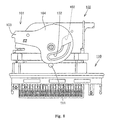
- Figs. 7 through 9 show a conventional lever-type connector.
- a lever 101 is rotatably supported by a first connector housing 100 which fits into a mating second connector housing 110 in order to make electrical connection between arrays of terminals in the housings 100,110.
- Cam pins 111 on the second connector housing 110 engage cam grooves 102 of the lever 101.
- the lever 101 has a pair of plate-shaped arm portions 104, one on each side of the housing, extending to an operation portion 103.
- the cam grooves 102 are formed on the respective arm portions 104.
- the lever 101 When fitting the two connector housings 100, 110 to each other, the lever 101 is set in a predetermined waiting posture with the entrance 102A of the cam groove 102 open toward the second connector housing 110. In this state, the connector housings 100, 110 are approached to each other parallel to the surface of the arm portion 26 and partially fitted into each other so that the cam pin 111 penetrates into the entrance 102A of the cam groove 102 on each side. The lever 101 is rotated, drawing the connector housings 100, 110 tightly together by a cam action due to the engagement between the cam grooves 102 and the cam pins 111.
- This kind of lever-type connector is disclosed in JP-A-6-275337, corresponding to US-A-5 476 390, considered to represent the closest prior art.
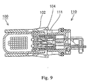
- the arm portion 104 disengages from the peripheral surface of the cam pin 111, and the connector housings 100, 110 may be fitted in each other incompletely, with the cam pin 111 and the cam groove 102 not in engagement with each other, as shown in Figs. 8 and 9.
- US-A-5,476,390 shows a connector similar to that of Figs. 7 to 9, in which the cam pins have a chamfer at their extremity, which may tend to encourage over-riding of the lever on the pin.
- a lever-type electrical connector comprising a pair of connector housings adapted to be fitted together in a fitted conformation to effect electrical connection, and a lever rotatably mounted on a first one of the connector housings for rotation between a waiting position and a locking position, the lever having surfaces defining a cam track.
- a cam follower is provided on the second of the connector housings in the form of an upstanding member located so as to enter the entrance end of the cam track when the connector housings are brought together in a predetermined fitting direction with the lever in the waiting position. The interaction of the cam follower and the cam track, when thereafter the lever is rotated to the locking position, causes the connector housings to be drawn together into the fitted conformation.
- At least one of the lever and the cam follower has an edge surface which is inclined relative to said fitting direction whereby, when the lever is at at least one rotational position such that the cam follower is not correctly received in the entrance end of the cam track, the lever and the cam follower interact at the inclined edge surface to prevent the lever over-riding on the cam follower.
- the lever has an arm portion in which the cam track is defined and the cam follower is a pin projecting outwardly from a face of the second connector housing.
- the arm portion and the pin interact at the inclined edge surface so as to urge the arm portion towards the face of the second connector housing.
- the pin may have a projecting flange which interacts with the inclined edge surface to urge the arm portion towards the second connector housing.
- both the lever and the cam follower have edge surfaces inclined relative to the fitting direction, the two edge surfaces interacting to prevent the lever over-riding the cam follower.
- the inclined peripheral edge which is for example on an arm portion of the lever, collides with the cam pin.
- the inclined surface subjects the arm portion to a guiding force towards the connector housing, not away from it. Therefore, the arm portion is prevented from being lifted from the cam pin.
- the inclination of the inclined surface it is preferable to make the inclination of the inclined surface gentle to allow the guiding operation of the inclined surface to be performed smoothly. If the tapered surface having a gentle inclination is formed on the cam pin, it may be necessary to increase the diameter of the cam pin, but there are dimensional restrictions in its design. Preferably therefore the inclined surface is formed on the arm portion and can be much larger than on the cam pin. Thus, the inclination of the inclined surface can be set as desired. Preferably this inclination of the inclined surface is at not more than 60°, more preferably not more than 45° to the insertion direction.
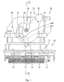
- Fig. 1 is a plan view of a connector which is a first embodiment of the invention, showing a state in which the two connector housings of the connector are separated from each other.
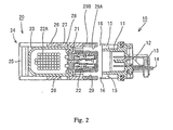
- Fig. 2 is a sectional view of the connector of Fig. 1 on line II-II of Fig. 1 showing a state in which the two connector housings are separated from each other.
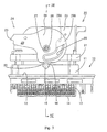
- Fig. 3 is a plan view of the connector of Fig. 1 showing a state in which the two connector housings are fitted to each other, with the lever located at an incorrect position.
- Fig. 4 is a sectional view on line IV-IV of Fig. 3.
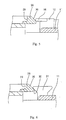
- Fig. 5 is a partial enlarged diagrammatic side view showing an arm portion of the lever and a cam pin interfering with each other, when the lever is located at the incorrect position.
- Fig. 6 is a partial diagrammatic view, corresponding to Fig. 5 of the lever and cam pin in a second embodiment of the invention.
- Fig. 7 is a perspective view showing a conventional lever-type connector.
- Fig. 8 is a plan view of the connector of Fig. 7.
- Fig. 9 is a sectional view of the connector of Fig. 7.
- the connector is composed of a male connector housing 10 and a female connector housing 20 which can be detachably fitted to each other.
- the male connector housing 10 is for example installed on a circuit substrate (not shown).
- the male connector housing 10 has a generally rectangular hood portion 11 open in a forward direction and a rear wall portion 12 sealing the rear end of the hood portion 11.
- L-shaped long and narrow male metal terminal fittings 13 are fixed in and penetrate through the rear wall portion 12.
- One end of each male metal terminal fitting 13 projects into the hood portion 11, whereas the other end thereof penetrates downward through an alignment plate 14 installed on the housing 10.
- Cam pins 15 are formed coaxially on the upper surface and lower surface of the housing 10.
- the cam pin 15 is mainly cylindrical and has a uniform outer diameter in its axial direction.
- a semi-circular arc-shaped lip or flange 16 of larger diameter projects outward from the periphery of the top (outer) end of each cam pin 15 extending around about the half of the periphery thereof so as to be directed towards the female connector housing 20.
- the female connector housing 20 has a body 21 accommodating female metal terminal fittings 22, a cover 23 disposed rearwardly from the rear surface of the body 21 and guiding electric wires 22A in a lateral direction, and a lever 24 installed on the cover 23.
- the lever 24 has a pair of upper and lower planar sheet-like arm portions 26 joined integrally by an operating portion (handle) 25 at which force is applied to move it.
- the lever 24 is installed on the cover 23 by fitting a spigot or shaft 28 on each side of the cover 23 into a bearing hole 27 of the respective arm portion 26.
- the lever 24 rotates on the shafts 28 between the waiting position shown in Fig. 1 and the fitted position shown in Fig. 3.
- the arm portion 26 rotates parallel to and close to the outer surface of the body 21 and that of the cover 23.
- the arm portion 26 is parallel with the mutual fitting direction of the male and female connector housings 10, 20.
- a curved cam groove 29 constituting a cam track is formed on each arm portion 26 and extends partially around the shaft 28.
- the cam groove 29 is open as a slot on both the inner and outer surfaces of the arm portion 26 except at an entrance 29A to the groove which is open at the peripheral edge of the arm portion 26.
- a reinforcing plate 29B closes over the entrance 29A of the groove 29 at the outer side of the arm portion 26.
- the peripheral edge of the arm portion 26 adjacent the groove 29 is curved to extend almost parallel with the outer edge of the groove 29.
- the lever 24 is not set at the waiting position i.e. the entrance 29A of the cam groove 29 does not confront the cam pin 15 but is displaced laterally from it.
- the peripheral surface of the cam pin 15 and the peripheral edge of the arm portion 26 contact each other.
- the arm portion deforms and rides over the front-end (upper end) surface of the cam pin. As a result, the connector housings are fitted in each other incompletely.
- the lever-type connector of this embodiment of the invention has means for preventing the deformation of the arm portion 26.
- a chamfer or tapered surface 30 is formed on the peripheral edge of each arm portion 26 by forming the outer surface of the arm portion 26 at an inclination with respect to the fitting direction of the housings 10, 20 along a region adjacent the inner end of the groove 29 remote from the groove entrance 29A, i.e. at the location which confronts the pin 15 if the lever 24 is in the fitting position of Fig. 3. This region of the periphery therefore interferes with the cam pin 15 when the lever 24 is located in the fitting position mistakenly, not in the waiting position.
- the tapered surface 30 contacts the innerside edge of the lip 16 of the cam pin 15 (side towards the hood 11) as the housings 10, 20 approach each other. Thereafter, force applied to move the housings 10, 20 towards each other acts to displace the peripheral edge of the arm portion 26 inward, i.e. towards the cover 23.
- the tapered surface 30 It is preferable to make the inclination of the tapered surface 30 gentle to allow its guiding operation to be performed smoothly. If a tapered surface having a gentle inclination is formed on the cam pin 15, it is necessary to increase the diameter of the cam pin 15, but there are dimensional restrictions in its design. However, in the embodiment, the tapered surface 30 is formed on the arm portion 26 which is much larger than the cam pin 15. Thus, the inclination of the tapered surface 30 can be set as desired.
- a lever-type connector which is a second embodiment of the invention is shown partially in Fig. 6. Only the point at which this embodiment differs from that of Figs. 1 to 5 is described.
- the tapered surface 30 is formed on only the arm portion 26, whereas in the second embodiment, the tapered surface is formed both on the arm portion and the cam pin.
- the cam pin 31 of the second embodiment is tapered so that its diameter increases toward its outer end (upper end in Fig. 6) to form a tapered surface 32 on the underside of the head of the cam pin 31.
- the lip 16 of Figs. 1 to 5 is not present.
- the engagement of the tapered surface with the pin 31 is indicated in Fig. 6.
Landscapes
- Details Of Connecting Devices For Male And Female Coupling (AREA)
Claims (5)
- Connecteur électrique du type à levier, comprenant :caractérisé en ce qu'au moins un du dit levier (24) et du dit palpeur de came (15) présente une surface de bord (30, 32) qui est inclinée par rapport à la dite direction d'assemblage d'une manière telle que, lorsqu'on rapproche les dits boítiers de connecteur l'un de l'autre et que le dit levier est à au moins une position de rotation dans laquelle le dit palpeur de came (15) n'est pas reçu dans la dite extrémité d'entrée (29A) du dit chemin de came, le dit levier (24) et le dit palpeur de came (15) coopèrent, à l'endroit de la dite surface de bord (30, 32), pour empêcher le dit levier de monter sur le dit palpeur de came.deux boítiers de connecteur (10, 20) prévus pour s'accoupler l'un à l'autre dans une configuration assemblée, afin d'effectuer une connexion électrique,un levier (24) monté de façon tournante sur un premier des dits boítiers de connecteur pour rotation entre une position d'attente et une position de verrouillage, le dit levier définissant un chemin de came (29) avec une extrémité d'entrée (29A),un palpeur de came (15) prévu sur le deuxième des dits boítiers de connecteur, sous la forme d'un élément en saillie placé de façon à entrer dans la dite extrémité d'entrée (29A) du dit chemin de came (29) lorsqu'on rapproche les dits boítiers de connecteur l'un de l'autre dans une direction d'assemblage prédéterminée, avec le dit levier dans sa dite position d'attente, l'interaction du dit palpeur de came et du dit chemin de came, lorsqu'on fait pivoter ensuite le dit levier (24) à la dite position de verrouillage, provoquant un accouplement des dits boítiers de connecteur (10, 20) dans la dite configuration assemblée,
- Connecteur électrique du type à levier selon la revendication 1, dans lequel le dit levier (24) comprend une partie formant bras (26) dans laquelle le dit chemin de came est défini, et le dit palpeur de came est une tige (15) faisant saillie vers l'extérieur à partir d'une face du dit deuxième boítier de connecteur, et la dite partie de bras (26) et la dite tige (15) coopèrent à l'endroit de la dite surface de bord (30, 32) de façon à solliciter la dite partie de bras vers la dite face du deuxième boítier de connecteur.
- Connecteur électrique du type à levier selon la revendication 2, dans lequel la dite surface de bord (30) est prévue sur la dite partie de bras (26).
- Connecteur électrique du type à levier selon la revendication 3, dans lequel la dite tige (15) comporte une collerette en saillie (16) qui coopère avec la dite surface de bord (30) sur la dite partie de bras (26) pour solliciter la dite partie de bras vers la dite face du dit deuxième boítier de connecteur.
- Connecteur électrique du type à levier selon une quelconque des revendications 1 à 3, dans lequel chacun du dit levier 24) et du dit palpeur de came (15) présente une dite surface de bord (30, 32) inclinée par rapport à la dite direction d'assemblage, les dites surfaces de bord (30, 32) coopérant pour empêcher le dit levier de monter sur le dit palpeur de came.
Applications Claiming Priority (2)
| Application Number | Priority Date | Filing Date | Title |
|---|---|---|---|
| JP11203119A JP2001035591A (ja) | 1999-07-16 | 1999-07-16 | レバー式コネクタ |
| JP20311999 | 1999-07-16 |
Publications (2)
| Publication Number | Publication Date |
|---|---|
| EP1069653A1 EP1069653A1 (fr) | 2001-01-17 |
| EP1069653B1 true EP1069653B1 (fr) | 2002-03-06 |
Family
ID=16468725
Family Applications (1)
| Application Number | Title | Priority Date | Filing Date |
|---|---|---|---|
| EP00305645A Expired - Lifetime EP1069653B1 (fr) | 1999-07-16 | 2000-07-05 | Connecteur à levier |
Country Status (4)
| Country | Link |
|---|---|
| US (1) | US6203340B1 (fr) |
| EP (1) | EP1069653B1 (fr) |
| JP (1) | JP2001035591A (fr) |
| DE (1) | DE60000084T2 (fr) |
Cited By (4)
| Publication number | Priority date | Publication date | Assignee | Title |
|---|---|---|---|---|
| DE102007031189A1 (de) | 2007-07-04 | 2009-01-15 | Wago Verwaltungsgesellschaft Mbh | Steckverbinder |
| US10950970B2 (en) | 2018-04-04 | 2021-03-16 | Commscope Technologies Llc | Ganged coaxial connector assembly |
| US10978840B2 (en) | 2018-04-04 | 2021-04-13 | Commscope Technologies Llc | Ganged coaxial connector assembly |
| US11527846B2 (en) | 2016-02-12 | 2022-12-13 | Commscope Technologies Llc | Ganged coaxial connector assembly |
Families Citing this family (15)
| Publication number | Priority date | Publication date | Assignee | Title |
|---|---|---|---|---|
| JP4156774B2 (ja) * | 2000-05-01 | 2008-09-24 | 住友電装株式会社 | レバー式コネクタ |
| JP3603760B2 (ja) * | 2000-08-11 | 2004-12-22 | 住友電装株式会社 | レバー式コネクタ |
| KR100383743B1 (ko) * | 2000-10-14 | 2003-05-14 | 한국몰렉스 주식회사 | 라이트 앵글형 abs용 커넥터 조립체 |
| US6619970B2 (en) * | 2001-09-25 | 2003-09-16 | Yazaki Corporation | Lever fitting-type manual disconnector |
| US6666697B2 (en) * | 2001-10-29 | 2003-12-23 | Sumitomo Wiring Systems, Ltd. | Connector assembly |
| JP2003249309A (ja) * | 2002-02-26 | 2003-09-05 | Sumitomo Wiring Syst Ltd | 分割コネクタ |
| US7267564B2 (en) * | 2005-12-01 | 2007-09-11 | Molex Incorporated | Lever type electrical connector |
| JP4893596B2 (ja) * | 2007-11-15 | 2012-03-07 | 住友電装株式会社 | コネクタ |
| US7559779B1 (en) | 2008-05-14 | 2009-07-14 | Cinch Connectors, Inc. | Electrical connector |
| FR2966649B1 (fr) * | 2010-10-26 | 2013-06-28 | Tyco Electronics France Sas | Connecteur a engagement sur |
| DE102013216829A1 (de) | 2013-08-23 | 2015-02-26 | Tyco Electronics Amp Gmbh | Anordnung zur erleichterten Verbindung oder Trennung eines Steckers und eines Gegensteckers |
| JP2016207414A (ja) * | 2015-04-21 | 2016-12-08 | 住友電装株式会社 | コネクタ |
| JP6574798B2 (ja) * | 2017-02-28 | 2019-09-11 | 矢崎総業株式会社 | レバー式コネクタ |
| US10135183B1 (en) * | 2017-10-20 | 2018-11-20 | Lear Corporation | Electrical connector with assist lever |
| JP1706310S (ja) * | 2021-06-18 | 2022-01-31 | 電気コネクタ用ハウジング |
Family Cites Families (5)
| Publication number | Priority date | Publication date | Assignee | Title |
|---|---|---|---|---|
| GB2260865B (en) * | 1991-10-21 | 1996-03-27 | Sumitomo Wall Systems Ltd | Lever type connector |
| JP2772309B2 (ja) * | 1993-03-17 | 1998-07-02 | 矢崎総業株式会社 | レバー結合式コネクタ |
| JP2817088B2 (ja) * | 1994-02-23 | 1998-10-27 | 矢崎総業株式会社 | レバーロックの補強構造 |
| JP3123422B2 (ja) * | 1996-02-15 | 2001-01-09 | 住友電装株式会社 | レバー式コネクタ |
| JP3457172B2 (ja) * | 1998-03-04 | 2003-10-14 | 矢崎総業株式会社 | コネクタ嵌合構造 |
-
1999
- 1999-07-16 JP JP11203119A patent/JP2001035591A/ja active Pending
-
2000
- 2000-07-05 DE DE60000084T patent/DE60000084T2/de not_active Expired - Fee Related
- 2000-07-05 EP EP00305645A patent/EP1069653B1/fr not_active Expired - Lifetime
- 2000-07-14 US US09/617,443 patent/US6203340B1/en not_active Expired - Lifetime
Cited By (7)
| Publication number | Priority date | Publication date | Assignee | Title |
|---|---|---|---|---|
| DE102007031189A1 (de) | 2007-07-04 | 2009-01-15 | Wago Verwaltungsgesellschaft Mbh | Steckverbinder |
| DE102007031189B4 (de) * | 2007-07-04 | 2010-07-08 | Wago Verwaltungsgesellschaft Mbh | Set aus einem Gegensteckverbinder und einem Steckverbinder |
| US11527846B2 (en) | 2016-02-12 | 2022-12-13 | Commscope Technologies Llc | Ganged coaxial connector assembly |
| US10950970B2 (en) | 2018-04-04 | 2021-03-16 | Commscope Technologies Llc | Ganged coaxial connector assembly |
| US10978840B2 (en) | 2018-04-04 | 2021-04-13 | Commscope Technologies Llc | Ganged coaxial connector assembly |
| US11824316B2 (en) | 2018-04-04 | 2023-11-21 | Commscope Technologies Llc | Ganged coaxial connector assembly |
| US12237614B2 (en) | 2018-04-04 | 2025-02-25 | Outdoor Wireless Networks LLC | Ganged coaxial connector assembly |
Also Published As
| Publication number | Publication date |
|---|---|
| DE60000084T2 (de) | 2002-09-12 |
| US6203340B1 (en) | 2001-03-20 |
| EP1069653A1 (fr) | 2001-01-17 |
| JP2001035591A (ja) | 2001-02-09 |
| DE60000084D1 (de) | 2002-04-11 |
Similar Documents
| Publication | Publication Date | Title |
|---|---|---|
| EP1069653B1 (fr) | Connecteur à levier | |
| US20080119074A1 (en) | Connector and a connector assembly | |
| JP2641661B2 (ja) | オーバモールドシールドコネクタ | |
| US7238050B2 (en) | Shielded connector | |
| EP1981128B1 (fr) | Connecteur à levier et arrangement du connecteur | |
| US7300294B2 (en) | Connector and connector assembly of the movable member type | |
| CN100452560C (zh) | 杠杆式连接器 | |
| EP1672747B1 (fr) | Connecteur | |
| EP1571734B1 (fr) | Dispositif de connexion ayant un élément de détection de l'engagement appelé assurance de position de connecteurs | |
| JPH0542119B2 (fr) | ||
| JP3275290B2 (ja) | レバー式コネクタ | |
| US7258557B2 (en) | Pivotal lever-type connector | |
| US6863551B2 (en) | Connector, set of connectors and method of connecting a connector | |
| EP0854546B1 (fr) | Verrouillage double pour connecteur | |
| US20060051993A1 (en) | Lever action mechanical assist connector | |
| CN111697374B (zh) | 杆式连接器 | |
| US6648659B2 (en) | Lever-type connector and a method for mounting a lever-type connector into a hole of a panel | |
| US20070032107A1 (en) | Pivotal lever-type connector | |
| EP1043811B1 (fr) | Connecteur électrique à fiches, en particulier pour l'application aux véhicules automobiles | |
| JPH11297421A (ja) | ロック部材付きコネクタ | |
| US7063548B2 (en) | Connector and connector assembly | |
| CN112470347B (zh) | 杆式连接器 | |
| US6638099B2 (en) | Connector | |
| JP2002359037A (ja) | レバー式コネクタ | |
| JP2025016992A (ja) | レバー式コネクタ |
Legal Events
| Date | Code | Title | Description |
|---|---|---|---|
| PUAI | Public reference made under article 153(3) epc to a published international application that has entered the european phase |
Free format text: ORIGINAL CODE: 0009012 |
|
| 17P | Request for examination filed |
Effective date: 20000726 |
|
| AK | Designated contracting states |
Kind code of ref document: A1 Designated state(s): DE FR GB IT |
|
| AX | Request for extension of the european patent |
Free format text: AL;LT;LV;MK;RO;SI |
|
| GRAG | Despatch of communication of intention to grant |
Free format text: ORIGINAL CODE: EPIDOS AGRA |
|
| 17Q | First examination report despatched |
Effective date: 20010615 |
|
| GRAG | Despatch of communication of intention to grant |
Free format text: ORIGINAL CODE: EPIDOS AGRA |
|
| GRAH | Despatch of communication of intention to grant a patent |
Free format text: ORIGINAL CODE: EPIDOS IGRA |
|
| AKX | Designation fees paid |
Free format text: DE FR GB IT |
|
| GRAH | Despatch of communication of intention to grant a patent |
Free format text: ORIGINAL CODE: EPIDOS IGRA |
|
| REG | Reference to a national code |
Ref country code: GB Ref legal event code: IF02 |
|
| GRAA | (expected) grant |
Free format text: ORIGINAL CODE: 0009210 |
|
| AK | Designated contracting states |
Kind code of ref document: B1 Designated state(s): DE FR GB IT |
|
| REF | Corresponds to: |
Ref document number: 60000084 Country of ref document: DE Date of ref document: 20020411 |
|
| ET | Fr: translation filed | ||
| PLBE | No opposition filed within time limit |
Free format text: ORIGINAL CODE: 0009261 |
|
| STAA | Information on the status of an ep patent application or granted ep patent |
Free format text: STATUS: NO OPPOSITION FILED WITHIN TIME LIMIT |
|
| 26N | No opposition filed |
Effective date: 20021209 |
|
| PGFP | Annual fee paid to national office [announced via postgrant information from national office to epo] |
Ref country code: GB Payment date: 20060705 Year of fee payment: 7 |
|
| GBPC | Gb: european patent ceased through non-payment of renewal fee |
Effective date: 20070705 |
|
| PG25 | Lapsed in a contracting state [announced via postgrant information from national office to epo] |
Ref country code: GB Free format text: LAPSE BECAUSE OF NON-PAYMENT OF DUE FEES Effective date: 20070705 |
|
| PGFP | Annual fee paid to national office [announced via postgrant information from national office to epo] |
Ref country code: FR Payment date: 20090710 Year of fee payment: 10 |
|
| PGFP | Annual fee paid to national office [announced via postgrant information from national office to epo] |
Ref country code: DE Payment date: 20090702 Year of fee payment: 10 |
|
| PGFP | Annual fee paid to national office [announced via postgrant information from national office to epo] |
Ref country code: IT Payment date: 20090720 Year of fee payment: 10 |
|
| REG | Reference to a national code |
Ref country code: FR Ref legal event code: ST Effective date: 20110331 |
|
| PG25 | Lapsed in a contracting state [announced via postgrant information from national office to epo] |
Ref country code: DE Free format text: LAPSE BECAUSE OF NON-PAYMENT OF DUE FEES Effective date: 20110201 |
|
| REG | Reference to a national code |
Ref country code: DE Ref legal event code: R119 Ref document number: 60000084 Country of ref document: DE Effective date: 20110201 |
|
| PG25 | Lapsed in a contracting state [announced via postgrant information from national office to epo] |
Ref country code: FR Free format text: LAPSE BECAUSE OF NON-PAYMENT OF DUE FEES Effective date: 20100802 Ref country code: IT Free format text: LAPSE BECAUSE OF NON-PAYMENT OF DUE FEES Effective date: 20100705 |