EP1069629A2 - Verfahren zum Montieren eines Temperaturdetektors in einer Batterie - Google Patents
Verfahren zum Montieren eines Temperaturdetektors in einer Batterie Download PDFInfo
- Publication number
- EP1069629A2 EP1069629A2 EP00305960A EP00305960A EP1069629A2 EP 1069629 A2 EP1069629 A2 EP 1069629A2 EP 00305960 A EP00305960 A EP 00305960A EP 00305960 A EP00305960 A EP 00305960A EP 1069629 A2 EP1069629 A2 EP 1069629A2
- Authority
- EP
- European Patent Office
- Prior art keywords
- sensor
- temperature detection
- detection hole
- temperature
- temperature sensor
- Prior art date
- Legal status (The legal status is an assumption and is not a legal conclusion. Google has not performed a legal analysis and makes no representation as to the accuracy of the status listed.)
- Granted
Links
Images



Classifications
-
- H—ELECTRICITY
- H01—ELECTRIC ELEMENTS
- H01M—PROCESSES OR MEANS, e.g. BATTERIES, FOR THE DIRECT CONVERSION OF CHEMICAL ENERGY INTO ELECTRICAL ENERGY
- H01M50/00—Constructional details or processes of manufacture of the non-active parts of electrochemical cells other than fuel cells, e.g. hybrid cells
-
- H—ELECTRICITY
- H01—ELECTRIC ELEMENTS
- H01M—PROCESSES OR MEANS, e.g. BATTERIES, FOR THE DIRECT CONVERSION OF CHEMICAL ENERGY INTO ELECTRICAL ENERGY
- H01M10/00—Secondary cells; Manufacture thereof
- H01M10/42—Methods or arrangements for servicing or maintenance of secondary cells or secondary half-cells
- H01M10/48—Accumulators combined with arrangements for measuring, testing or indicating the condition of cells, e.g. the level or density of the electrolyte
- H01M10/486—Accumulators combined with arrangements for measuring, testing or indicating the condition of cells, e.g. the level or density of the electrolyte for measuring temperature
-
- H—ELECTRICITY
- H01—ELECTRIC ELEMENTS
- H01M—PROCESSES OR MEANS, e.g. BATTERIES, FOR THE DIRECT CONVERSION OF CHEMICAL ENERGY INTO ELECTRICAL ENERGY
- H01M50/00—Constructional details or processes of manufacture of the non-active parts of electrochemical cells other than fuel cells, e.g. hybrid cells
- H01M50/50—Current conducting connections for cells or batteries
- H01M50/569—Constructional details of current conducting connections for detecting conditions inside cells or batteries, e.g. details of voltage sensing terminals
-
- Y—GENERAL TAGGING OF NEW TECHNOLOGICAL DEVELOPMENTS; GENERAL TAGGING OF CROSS-SECTIONAL TECHNOLOGIES SPANNING OVER SEVERAL SECTIONS OF THE IPC; TECHNICAL SUBJECTS COVERED BY FORMER USPC CROSS-REFERENCE ART COLLECTIONS [XRACs] AND DIGESTS
- Y02—TECHNOLOGIES OR APPLICATIONS FOR MITIGATION OR ADAPTATION AGAINST CLIMATE CHANGE
- Y02E—REDUCTION OF GREENHOUSE GAS [GHG] EMISSIONS, RELATED TO ENERGY GENERATION, TRANSMISSION OR DISTRIBUTION
- Y02E60/00—Enabling technologies; Technologies with a potential or indirect contribution to GHG emissions mitigation
- Y02E60/10—Energy storage using batteries
Definitions
- the present invention relates to a rechargeable battery, and more particularly, to an improvement of the temperature detection portion in a sealed rechargeable battery wherein elements for electromotive force are accommodated in a sealed battery case.
- an embedded-type structure wherein a temperature sensing element is integrally provided in the battery case.
- a temperature detection hole having a bottom is formed in the battery case, which is sealed against the inside of the battery case and open to the outside, and a temperature sensor element is inserted into this temperature detection hole, which is then filled with a synthetic resin to integrate it into one piece with the battery case.
- a configuration in which a temperature sensor is inserted into a temperature detection hole having a bottom, as described above, and bonded or welded with an adhesive or a resin, or fixed by other means, so that the temperature inside the battery can be detected from outside the battery.
- the present invention provides a rechargeable battery, comprising: a battery case for accommodating therein elements for electromotive force in a sealed condition; a temperature detection hole which is defined by a cylindrical cavity having a bottom formed in the battery case; a temperature sensor mounted in the temperature detection hole, having a sensing end at a lower end thereof; and a mounting means for mounting the temperature sensor removably in the temperature detection hole such that the sensing end at the lower end of the temperature sensor is tightly pressed against the bottom of the temperature detection hole.
- the battery temperature can be detected with high precision and responsiveness. Moreover, since the temperature sensor can be removed from the temperature detection hole of the battery case, the operability when attaching the temperature sensor and when replacing the batteries for maintenance is good.
- an engaging hook is provided at an edge portion of the temperature detection hole in the battery case, while an engaging flange that is elastically deformable is formed on the temperature sensor, so that, when the temperature sensor is mounted in the temperature detection hole, the elastic restorative force of the engaging flange that is engaged in elastic deformation with the engaging hook exerts pressure on the temperature sensor.
- the temperature sensor can be mounted with one-touch operation.
- the elastic restorative force of the engaging flange presses the sensing end of the temperature sensor securely against the bottom wall of the temperature detection hole.
- the temperature detection hole and the temperature sensor respectively have small-diameter portions at their lower ends, so that heat is conducted to the sensing end of the temperature sensor not only from the bottom wall of the temperature detection hole, but also from the vicinity thereof, which enables temperature detection with even higher precision and responsiveness, because the thermal capacity of the temperature detection portion is small.
- the temperature sensor comprises a cylindrical sensor case having a bottom wall, and a sensing element inserted into the sensor case such as to contact the bottom wall of the sensor case, the interior of the sensor case being filled with a resin. Thanks to the construction wherein the sensing element is arranged inside the sensor case and formed in one piece with the sensor case, there is no danger that the leads break off the sensing element, whereby handling is made easier, and temperature detection with high responsiveness and smooth thermal conduction becomes possible. The responsiveness of the temperature sensor can be further improved by making the bottom wall of the sensor case thinner.
- the temperature sensor comprises a cylindrical sensor case without a bottom, and a sensing element inserted into the sensor case such as to extend through the sensor case, the interior of the sensor case being filled with a resin. Thanks to the construction wherein the perimeter of the sensing element is protected by the sensor case and the filling resin, and that the sensing element is formed in one piece with the sensor case, there is no danger that the leads break off the sensing element, whereby handling is made easier. This also enables temperature detection with even higher responsiveness, because heat is conducted directly from the bottom wall of the temperature detection hole to the sensing element.
- the temperature sensor is further provided with a wire-holding hook for holding the wires, so that stress concentrations in the wires in a direction in which they are pulled out of the temperature sensor, which may cause wire rupture, can be prevented, even when an external force is accidentally applied to the wires.
- the engaging hook is elastically deformable in a direction that is perpendicular to an axis direction of the temperature detection hole, and the temperature sensor comprises a protrusion that restricts displacement of the engaging hook, so that excessive deformation that may cause breaking of the engaging hooks when mounting or removing the temperature sensor can be prevented.
- the temperature detection hole of the battery case, the sensor case of the temperature sensor and the mounting means are all made of synthetic resin, so that heat is not dispersed to the outside, thereby making appropriate temperature detection possible.
- the temperature detection hole of the battery case is arranged such that its bottom wall is in contact with or in close proximity to a maximum temperature location of the elements for electromotive force, for example, at an upper central portion of the elements for electromotive force or near the collectors, where the temperature is the highest and heat is dissipated the slowest, whereby the temperature of the battery can be detected with high responsiveness.
- the present invention is applied to a battery pack of nickel metal hydride batteries, which is suitable for use as a drive power source for an electric vehicle.
- a battery pack of nickel metal hydride batteries which is suitable for use as a drive power source for an electric vehicle.
- a plurality of rechargeable batteries 1 are arranged side by side, and connected electrically in series for use.
- Coolant passages 2 are formed between opposing walls of adjacent batteries 1 for forcibly cooling the batteries 1.
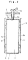
- the rechargeable batteries 1 each comprise battery cases 3 made of hollow prismatic case bodies 4, of which upper open ends are closed integrally by a lid member 5. Elements for electromotive force 6 are accommodated inside each of the battery cases 3.
- the case bodies 4 and the lid member 5 that constitute battery cases 3 are made of a synthetic resin material, such as a PP/PPE alloy.
- Positive electrode terminals and negative electrode terminals are arranged at both ends of the battery cases 3 in a longitudinal direction and a safety vent (not shown in the drawings) for releasing pressure when the pressure in the battery cases 3 has exceeded a certain value is arranged at a suitable location in the lid member 5.
- the elements for electromotive force 6 are constituted by layering positive electrode plates 7 comprising Ni foamed metal and negative electrode plates 8 comprising Ni punched metal coated with active materials, with intervening separators 9 in the form of a bag covering the positive electrode plates 7.
- These electrode plates are accommodated inside the battery cases 3 together with a liquid electrolyte.
- the lateral edges of the group of positive electrode plates 7 protrude beyond the group of negative electrode plates 8 on one side, and the lateral edges of the group of negative electrode plates 8 protrude beyond the group of positive electrode plates 7 on the opposite side, and these protruding lateral portions form the lead portions 7a and 8a, which are coupled together as one by collector plates 10, 11.
- the collector plates 10, 11 are connected to the above-mentioned positive electrode terminals and negative electrode terminals, respectively.
- a bottom wall 12a at the bottom end of this temperature detection hole 12 is arranged in contact with or in close proximity to an upper central portion of the elements for electromotive force 6, which exhibits a maximum temperature inside the rechargeable battery.
- a temperature sensor 13 is mounted removably in the temperature detection hole 12 and the sensor end 13a at the tip of the temperature sensor 13 is pressed against the bottom wall 12a of the temperature detection hole 12a.
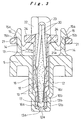
- a small-diameter portion 12b whose diameter is smaller than that of the other portions is formed at the bottom end of the temperature detection hole 12.
- a pair of engaging hooks 14 protrude from the two lateral portions of the upper open end of the temperature detection hole 12. These engaging hooks 14 are elastically deformable, so that their tip portions can be moved closer to or away from each other.
- the engaging hooks 14 are formed with engaging claws 15 having a substantially triangular cross section and protruding toward the outside from the upper ends of the engaging hooks 14.
- the engaging claws 15 comprise guide faces 15a that incline toward the outside from the top ends of the engaging claws 15 and engaging faces 15b facing downward that are formed continuously from the lower ends of the guide faces 15a.
- the temperature sensor 13 comprises a cylindrical sensor case 16 having a bottom made of a synthetic resin, such as PE.
- a sensor element 17, such as a thermistor, is inserted into this sensor case 16 such that the sensor element 17 contacts the bottom wall 16a of the sensor case 16.
- the sensor case 16 is then filled with resin 18, such as an epoxy resin.
- resin 18, such as an epoxy resin At the lower end of the sensor case 16, a small-diameter portion 16b is formed so that the sensor element 17 can closely fit in the tip of the sensor case 16.
- the temperature sensor 13 has a small-diameter portion 13b that fits into the small-diameter portion 12b of the temperature detection hole 12.
- a tapered guide wall 16c is formed, so that the sensor element 17 can be inserted smoothly into the small-diameter portion 16b.
- Numeral 19 denotes leads extending from the sensor element 17, and numeral 20 denotes wires connected to the upper ends of the leads 19.
- the sensor element 17, the leads 19 and the wires 20 up to their distal ends are inserted into the sensor case 16 and integrated into one piece by filling the sensor case 16 with the resin 18.
- a pair of engaging flanges 21, which are formed in the shape of square frames when viewed from above so that the two engaging hooks 14 can be introduced therethrough and which can be elastically bent in a vertical direction, protrude from both sides of the upper end of the sensor case 16.
- the engaging flanges 21 are formed with curved portions 21a in the shape of letter "V" when viewed from the front at intermediate positions of the engaging flanges 21.
- a support piece 22 extends obliquely upward from the upper end of the sensor case 16 on one side in a direction orthogonal to the direction in which the two engaging flanges 21 oppose each other, and a U-shaped wire-holding hook 23 which faces downward and holds the wires 20 from above is provided at the tip of the support piece 22.
- protrusions 24 are formed on both sides of the upper end of the sensor case 16 toward the center of the inner side of the frame-shaped engaging flanges 21, so as to restrain the amount of displacement of the engaging hooks 14 to a certain extent.
- the temperature is detected by the sensor end 13a of the temperature sensor 13 that is pressed against the bottom wall 12a of the temperature detection hole 12, whereby temperature detection with high accuracy and responsiveness can be achieved. Also, because the bottom wall 12a of the temperature detection hole 12 is arranged in contact with or in close proximity to an upper central portion of the elements for electromotive force 6, the temperature at the portion of the battery where the temperature is the highest can be quickly detected. Precise battery control is possible by detecting the battery temperature with high accuracy and responsiveness in this manner, whereby the life-time and the reliability of the battery can be improved.
- the temperature detection hole 12 and the engaging hooks 14 of the battery cases 3, as well as the sensor case 16 and the engaging flanges 21 of the temperature sensor 13 are all made of a synthetic resin, their thermal conductivity is low. As compared to a case wherein the case where these parts are made of metal, temperature detection with high precision is possible, as there is no risk that heat is dispersed to the outside.
- the temperature sensor 13 When mounting the temperature sensor 13, it is simply inserted into the temperature detection hole 12 of the battery case 3, introducing the engaging hooks 14 through the frame-shaped engaging flanges 21, and pushing down the engaging flanges 21 to slide downward along the guide faces 15a of the engaging claws 15, whereby the engaging flanges 21 engage with the engaging faces 15b as elastically deformed downwards.
- the elastic restorative force of the engaging flanges 21 presses the sensing end 13a of the temperature sensor 13 securely against the bottom wall 12a of the temperature detection hole 12.
- Removal of the temperature sensor 13 can be accomplished also with a simple operation by releasing the engagement of the engaging faces 15b of the engaging claws 15 with the engaging flanges 21, by pushing the pair of engaging hooks 14 toward the inside. During the removal, the displacement of the engaging hooks 14 is restricted by the protrusions 24, so that there is no danger of deforming the engaging hooks 14 excessively and damaging same. Thanks to these simple operations for mounting and removing the temperature sensor 13, the operability when attaching the temperature sensor 13 and when replacing the rechargeable batteries 1 for maintenance is good.
- the temperature detection hole 12 is provided with a small-diameter portion 12b at the bottom end
- the temperature sensor 13 is provided with a small-diameter portion 13b at the lower end, whose diameters are smaller than those of other portions, so that heat is conducted to the sensing end 13a of the temperature sensor 13 not only from the bottom wall 12a of the temperature detection hole 12, but also from the vicinity thereof.
- the thermal capacity of the temperature detection portion is small. This enables temperature detection with even higher precision and responsiveness.
- the temperature sensor 13 itself is made by inserting the sensor element 17 into the cylindrical sensor case 16 having a bottom such as to contact the bottom wall 16a of the sensor case 16, and by filling the sensor case 16 with resin 18 to form one integrated piece. There is thus no danger that the leads 19 break off the sensor element 17, and handling of the temperature sensor 16 can thereby be made easy.
- such construction makes thermal conduction smooth, and enables temperature detection with high responsiveness. The responsiveness can be improved by making the bottom wall 16a of the sensor case 16 not thicker than, for example, 0.5mm. In this case, it is preferable that also the bottom wall 12a of the temperature detection hole 12 be made not thicker than, for example, 0.7mm.
- the temperature sensor 13 is provided with a wire-holding hook 23 for holding the wires 20, even when an external force is accidentally applied to the wires 20, there will be no stress concentrating at the ends of the wires 20 led out from the temperature sensor 13, and the wires will be prevented from rupturing.
- curved portions 21a are formed at intermediate positions of the engaging flanges 21 of the temperature sensor 13.
- the engaging flanges 21 are pushed downward while sliding along the guide faces 15a of the engaging claws 15 of the engaging hooks 14, the engaging hooks 14 are elastically deformed inward, and also the engaging flanges 21 are expanded somewhat at the curved portions 21a.
- a sensor element 17 such as a thermistor
- the sensor element 17 is inserted into a cylindrical sensor case 26 without a bottom wall so that the distal end thereof extends through the open end 26a of the sensor case 26, and the inside of the sensor case 26 is filled with a resin 18.
- Numeral 26b denotes a small-diameter portion
- numeral 26c denotes a tapered guide wall, which correspond to the small-diameter portion 16b and the tapered guide wall 16c of the foregoing embodiment, respectively.
- Fig. 6 shows one example, in which curved portions 21a are formed at intermediate portions of the engaging flanges 21, but it is also possible to omit the curved portions 21a in the intermediate portions of the engaging flanges 21, as shown in the example in Fig. 7, and to configure the intermediate portions as simple connection pieces 21b extending slantly downward.
- sealed battery cases accommodating therein elements for electromotive force are provided with a temperature detection hole having a bottom, which is sealed against the inside of the battery cases and open to the outside, and a mounting means is provided for mounting the temperature sensor in the temperature detection hole such as to be removable and such that its sensor end is pressed against the bottom wall of the temperature detection hole. Temperature detection is thereby possible while maintaining the inside of the battery cases tightly sealed. Since the sensor end of the temperature sensor is pressed against the bottom wall of the temperature detection hole, the battery temperature can be detected with high precision and responsiveness. Moreover, as the temperature sensor is removably mounted to the temperature detection hole, the operability when attaching the temperature sensor and when replacing the batteries for maintenance is good.
Landscapes
- Chemical & Material Sciences (AREA)
- Chemical Kinetics & Catalysis (AREA)
- Electrochemistry (AREA)
- General Chemical & Material Sciences (AREA)
- Engineering & Computer Science (AREA)
- Manufacturing & Machinery (AREA)
- Secondary Cells (AREA)
- Sealing Battery Cases Or Jackets (AREA)
- Battery Mounting, Suspending (AREA)
Applications Claiming Priority (2)
| Application Number | Priority Date | Filing Date | Title |
|---|---|---|---|
| JP20353499 | 1999-07-16 | ||
| JP20353499A JP4121104B2 (ja) | 1999-07-16 | 1999-07-16 | 二次電池 |
Publications (3)
| Publication Number | Publication Date |
|---|---|
| EP1069629A2 true EP1069629A2 (de) | 2001-01-17 |
| EP1069629A3 EP1069629A3 (de) | 2002-01-23 |
| EP1069629B1 EP1069629B1 (de) | 2013-05-22 |
Family
ID=16475755
Family Applications (1)
| Application Number | Title | Priority Date | Filing Date |
|---|---|---|---|
| EP00305960.7A Expired - Lifetime EP1069629B1 (de) | 1999-07-16 | 2000-07-13 | Verfahren zum Montieren eines Temperaturdetektors in einer Batterie |
Country Status (4)
| Country | Link |
|---|---|
| US (1) | US6610439B1 (de) |
| EP (1) | EP1069629B1 (de) |
| JP (1) | JP4121104B2 (de) |
| CN (1) | CN1175514C (de) |
Cited By (6)
| Publication number | Priority date | Publication date | Assignee | Title |
|---|---|---|---|---|
| FR2883103A1 (fr) * | 2005-03-09 | 2006-09-15 | Valeo Electronique Sys Liaison | Dispositif de mesure de la temperature d'une batterie |
| US7438988B2 (en) | 2004-11-12 | 2008-10-21 | Toyota Jidosha Kabushiki Kaisha | Rechargeable battery with surface mounted temperature detector |
| EP2600434A1 (de) * | 2011-12-01 | 2013-06-05 | Samsung SDI Co., Ltd. | Batteriemodul |
| EP1875582B1 (de) * | 2005-03-16 | 2017-02-22 | Ford Global Technologies, LLC | Stromversorgungssystem mit temperatursensorstationen |
| EP3151332A4 (de) * | 2014-05-29 | 2017-11-15 | Hitachi Automotive Systems, Ltd. | Leistungsspeichermodul |
| CN115290220A (zh) * | 2022-09-09 | 2022-11-04 | 利奥电子(南京)有限公司 | 一种用于新能源汽车电池检测的温度传感器及其检测方法 |
Families Citing this family (28)
| Publication number | Priority date | Publication date | Assignee | Title |
|---|---|---|---|---|
| DE10214368B4 (de) * | 2002-03-30 | 2007-09-13 | Robert Bosch Gmbh | Energiespeichermodul und dessen Verwendung für ein Elektrogerät |
| JP4569886B2 (ja) * | 2003-12-25 | 2010-10-27 | 株式会社大泉製作所 | 温度センサーの製造方法 |
| US7604896B2 (en) * | 2005-03-16 | 2009-10-20 | Ford Global Technologies, Llc | High voltage battery assembly for a motor vehicle |
| CN101395781B (zh) * | 2005-03-16 | 2011-09-14 | 福特全球技术公司 | 电源温度传感器和系统 |
| JP4694278B2 (ja) * | 2005-04-28 | 2011-06-08 | 本田技研工業株式会社 | バッテリユニット構造 |
| US7303333B2 (en) * | 2006-04-21 | 2007-12-04 | Mesure Technology Co., Ltd. | Thermometer with soft flexible probe |
| JP4791416B2 (ja) * | 2007-06-01 | 2011-10-12 | 矢崎総業株式会社 | 温度検出体の取付構造 |
| DE102007042404A1 (de) * | 2007-09-06 | 2009-03-12 | Robert Bosch Gmbh | Akkupack |
| JP5360951B2 (ja) * | 2008-01-25 | 2013-12-04 | 矢崎総業株式会社 | 温度センサ取付構造 |
| JP5001217B2 (ja) * | 2008-05-12 | 2012-08-15 | 矢崎総業株式会社 | 温度検出モジュールとその製造方法 |
| JP5179295B2 (ja) * | 2008-08-27 | 2013-04-10 | 株式会社パイオラックス | 温度センサの取付装置 |
| KR101075283B1 (ko) * | 2009-02-26 | 2011-10-19 | 에스비리모티브 주식회사 | 이차 전지 모듈 및 그 제조 방법 |
| US8287185B2 (en) * | 2009-10-01 | 2012-10-16 | Delphi Technologies, Inc. | Cell temperature sensing apparatus for a battery module |
| US9172068B2 (en) * | 2009-10-22 | 2015-10-27 | Samsung Sdi Co., Ltd. | Battery pack |
| WO2012078721A2 (en) | 2010-12-07 | 2012-06-14 | Allison Transmission, Inc. | Energy storage system for hybrid electric vehicle |
| JP5658581B2 (ja) * | 2011-01-28 | 2015-01-28 | 株式会社ニフコ | バッテリー用温度センサーの取付用クリップ |
| JP5484403B2 (ja) * | 2011-06-08 | 2014-05-07 | 本田技研工業株式会社 | バッテリモジュール |
| KR20130022503A (ko) * | 2011-08-24 | 2013-03-07 | 삼성에스디아이 주식회사 | 이차전지 |
| US20130095744A1 (en) * | 2011-10-17 | 2013-04-18 | Lennox Industries Inc. | Sensor mounting panel for an energy recovery ventilator unit |
| JP5619075B2 (ja) * | 2012-05-31 | 2014-11-05 | 本田技研工業株式会社 | 蓄電モジュール |
| DE102014212279A1 (de) | 2014-06-26 | 2015-12-31 | Robert Bosch Gmbh | Messanordnung zur Aufnahme eines Sensors |
| JP2019074327A (ja) * | 2017-10-12 | 2019-05-16 | 株式会社オートネットワーク技術研究所 | センサユニットおよび蓄電モジュール |
| CN110010344B (zh) * | 2019-05-08 | 2024-11-26 | 奕顺龙能源科技(北京)有限公司 | 储能元件以及电能存储装置 |
| JP7293453B2 (ja) * | 2020-08-06 | 2023-06-19 | 株式会社オートネットワーク技術研究所 | センサユニットおよび蓄電モジュール |
| JP7068397B2 (ja) * | 2020-08-06 | 2022-05-16 | 株式会社オートネットワーク技術研究所 | センサユニットおよび蓄電モジュール |
| US20240027029A1 (en) * | 2022-07-19 | 2024-01-25 | Cryoport, Inc. | Integrated vapor plug temperature monitoring |
| CN121642249A (zh) * | 2024-08-29 | 2026-03-10 | 宁德时代新能源科技股份有限公司 | 电池单体、电池装置及用电装置 |
| CN119447729A (zh) * | 2024-12-13 | 2025-02-14 | 蜂巢能源科技股份有限公司 | 电芯及电池包 |
Citations (1)
| Publication number | Priority date | Publication date | Assignee | Title |
|---|---|---|---|---|
| DE4400461C1 (de) | 1994-01-11 | 1995-01-19 | Deta Akkumulatoren | Temperatursensor für elektrochemische Akkumulatorenzellen |
Family Cites Families (9)
| Publication number | Priority date | Publication date | Assignee | Title |
|---|---|---|---|---|
| US4453835A (en) * | 1982-05-03 | 1984-06-12 | Clawson Burrell E | Temperature sensor |
| JPS6332874A (ja) | 1986-07-24 | 1988-02-12 | Matsushita Electric Works Ltd | 蓄電池の温度センサ取付構造 |
| US4752543A (en) * | 1987-04-02 | 1988-06-21 | Anderson Carl J | Universal terminal storage battery with handle |
| DE3735897A1 (de) | 1987-10-23 | 1989-05-03 | Asea Brown Boveri | Hochtemperaturbatterie |
| US5463375A (en) * | 1990-06-19 | 1995-10-31 | Dylec Ltd. | Status-reporting device for reporting a predetermined temperature state, temperature sensor suitable for such a status-reporting device, and process for the production of such a temperature sensor |
| US5261806A (en) * | 1992-02-26 | 1993-11-16 | Pleasant Ronald E | Electrically heated mold insert |
| JP3175558B2 (ja) | 1995-10-24 | 2001-06-11 | 松下電器産業株式会社 | 密閉形蓄電池 |
| JP3404257B2 (ja) * | 1997-07-11 | 2003-05-06 | 三菱電機株式会社 | 圧力センサ装置 |
| FR2770035B1 (fr) * | 1997-10-20 | 1999-12-10 | Alsthom Cge Alcatel | Batterie monobloc contenant un dispositif de mesure de la temperature interne |
-
1999
- 1999-07-16 JP JP20353499A patent/JP4121104B2/ja not_active Expired - Lifetime
-
2000
- 2000-07-11 US US09/613,628 patent/US6610439B1/en not_active Expired - Lifetime
- 2000-07-13 EP EP00305960.7A patent/EP1069629B1/de not_active Expired - Lifetime
- 2000-07-14 CN CNB001219081A patent/CN1175514C/zh not_active Expired - Lifetime
Patent Citations (1)
| Publication number | Priority date | Publication date | Assignee | Title |
|---|---|---|---|---|
| DE4400461C1 (de) | 1994-01-11 | 1995-01-19 | Deta Akkumulatoren | Temperatursensor für elektrochemische Akkumulatorenzellen |
Cited By (8)
| Publication number | Priority date | Publication date | Assignee | Title |
|---|---|---|---|---|
| US7438988B2 (en) | 2004-11-12 | 2008-10-21 | Toyota Jidosha Kabushiki Kaisha | Rechargeable battery with surface mounted temperature detector |
| FR2883103A1 (fr) * | 2005-03-09 | 2006-09-15 | Valeo Electronique Sys Liaison | Dispositif de mesure de la temperature d'une batterie |
| EP1875582B1 (de) * | 2005-03-16 | 2017-02-22 | Ford Global Technologies, LLC | Stromversorgungssystem mit temperatursensorstationen |
| EP2600434A1 (de) * | 2011-12-01 | 2013-06-05 | Samsung SDI Co., Ltd. | Batteriemodul |
| US9028994B2 (en) | 2011-12-01 | 2015-05-12 | Samsung Sdi Co., Ltd. | Battery module including sensing member pressed by terminal connecting member |
| EP3151332A4 (de) * | 2014-05-29 | 2017-11-15 | Hitachi Automotive Systems, Ltd. | Leistungsspeichermodul |
| US10230219B2 (en) | 2014-05-29 | 2019-03-12 | Hitachi Automotive Systems, Ltd. | Storage module |
| CN115290220A (zh) * | 2022-09-09 | 2022-11-04 | 利奥电子(南京)有限公司 | 一种用于新能源汽车电池检测的温度传感器及其检测方法 |
Also Published As
| Publication number | Publication date |
|---|---|
| JP2001035547A (ja) | 2001-02-09 |
| US6610439B1 (en) | 2003-08-26 |
| JP4121104B2 (ja) | 2008-07-23 |
| CN1281268A (zh) | 2001-01-24 |
| EP1069629A3 (de) | 2002-01-23 |
| CN1175514C (zh) | 2004-11-10 |
| EP1069629B1 (de) | 2013-05-22 |
Similar Documents
| Publication | Publication Date | Title |
|---|---|---|
| EP1069629B1 (de) | Verfahren zum Montieren eines Temperaturdetektors in einer Batterie | |
| JP7576747B2 (ja) | 電池 | |
| EP2463937B1 (de) | Speicherelement und Anschlusspolherstellungsverfahren | |
| JP5294697B2 (ja) | パック電池 | |
| US9159983B2 (en) | Battery, vehicle mounting the battery, and device mounting the battery | |
| CN100502125C (zh) | 具有放气安全孔的可再充电电池 | |
| TWI493774B (zh) | Waterproof construction of the battery system | |
| EP1093170A1 (de) | Modular aufgebaute Batterie | |
| EP3306702A1 (de) | Sekundärbatteriepack | |
| JP2016015331A (ja) | 組電池及び組電池用セパレータ | |
| JP2010277796A (ja) | パック電池 | |
| EP3297061A1 (de) | Batteriepack | |
| JP2009218012A (ja) | パック電池 | |
| EP3686986B1 (de) | Batteriemodul und batteriepack damit | |
| CN111566868B (zh) | 用于电动车辆中的电池组的电池单元 | |
| JP4953225B2 (ja) | 密閉角形電池 | |
| JP3540650B2 (ja) | 電源装置 | |
| EP1919010A1 (de) | Akku | |
| JP7542624B2 (ja) | バッテリーパック、電子デバイス、及び自動車 | |
| CN215644891U (zh) | 电池组 | |
| CN117795749A (zh) | 蓄电模块 | |
| US11251498B2 (en) | Secondary battery module | |
| JP3906979B2 (ja) | 蓄電池 | |
| KR102853425B1 (ko) | 이차전지 | |
| EP2343753A1 (de) | Batteriepack |
Legal Events
| Date | Code | Title | Description |
|---|---|---|---|
| PUAI | Public reference made under article 153(3) epc to a published international application that has entered the european phase |
Free format text: ORIGINAL CODE: 0009012 |
|
| AK | Designated contracting states |
Kind code of ref document: A2 Designated state(s): DE FR GB Kind code of ref document: A2 Designated state(s): AT BE CH CY DE DK ES FI FR GB GR IE IT LI LU MC NL PT SE |
|
| AX | Request for extension of the european patent |
Free format text: AL;LT;LV;MK;RO;SI |
|
| PUAL | Search report despatched |
Free format text: ORIGINAL CODE: 0009013 |
|
| AK | Designated contracting states |
Kind code of ref document: A3 Designated state(s): AT BE CH CY DE DK ES FI FR GB GR IE IT LI LU MC NL PT SE |
|
| AX | Request for extension of the european patent |
Free format text: AL;LT;LV;MK;RO;SI |
|
| 17P | Request for examination filed |
Effective date: 20020621 |
|
| AKX | Designation fees paid |
Free format text: DE FR GB |
|
| RAP1 | Party data changed (applicant data changed or rights of an application transferred) |
Owner name: TOYOTA JIDOSHA KABUSHIKI KAISHA Owner name: PANASONIC CORPORATION |
|
| 17Q | First examination report despatched |
Effective date: 20090422 |
|
| GRAP | Despatch of communication of intention to grant a patent |
Free format text: ORIGINAL CODE: EPIDOSNIGR1 |
|
| RAP1 | Party data changed (applicant data changed or rights of an application transferred) |
Owner name: PANASONIC CORPORATION Owner name: TOYOTA JIDOSHA KABUSHIKI KAISHA |
|
| GRAS | Grant fee paid |
Free format text: ORIGINAL CODE: EPIDOSNIGR3 |
|
| GRAA | (expected) grant |
Free format text: ORIGINAL CODE: 0009210 |
|
| AK | Designated contracting states |
Kind code of ref document: B1 Designated state(s): DE FR GB |
|
| REG | Reference to a national code |
Ref country code: GB Ref legal event code: FG4D |
|
| REG | Reference to a national code |
Ref country code: DE Ref legal event code: R096 Ref document number: 60048023 Country of ref document: DE Effective date: 20130718 |
|
| PLBE | No opposition filed within time limit |
Free format text: ORIGINAL CODE: 0009261 |
|
| STAA | Information on the status of an ep patent application or granted ep patent |
Free format text: STATUS: NO OPPOSITION FILED WITHIN TIME LIMIT |
|
| 26N | No opposition filed |
Effective date: 20140225 |
|
| REG | Reference to a national code |
Ref country code: DE Ref legal event code: R097 Ref document number: 60048023 Country of ref document: DE Effective date: 20140225 |
|
| REG | Reference to a national code |
Ref country code: FR Ref legal event code: PLFP Year of fee payment: 17 |
|
| REG | Reference to a national code |
Ref country code: DE Ref legal event code: R084 Ref document number: 60048023 Country of ref document: DE |
|
| REG | Reference to a national code |
Ref country code: GB Ref legal event code: 746 Effective date: 20170419 |
|
| REG | Reference to a national code |
Ref country code: FR Ref legal event code: PLFP Year of fee payment: 18 |
|
| REG | Reference to a national code |
Ref country code: FR Ref legal event code: PLFP Year of fee payment: 19 |
|
| PGFP | Annual fee paid to national office [announced via postgrant information from national office to epo] |
Ref country code: FR Payment date: 20190619 Year of fee payment: 20 |
|
| PGFP | Annual fee paid to national office [announced via postgrant information from national office to epo] |
Ref country code: DE Payment date: 20190702 Year of fee payment: 20 |
|
| PGFP | Annual fee paid to national office [announced via postgrant information from national office to epo] |
Ref country code: GB Payment date: 20190710 Year of fee payment: 20 |
|
| REG | Reference to a national code |
Ref country code: DE Ref legal event code: R071 Ref document number: 60048023 Country of ref document: DE |
|
| REG | Reference to a national code |
Ref country code: GB Ref legal event code: PE20 Expiry date: 20200712 |
|
| PG25 | Lapsed in a contracting state [announced via postgrant information from national office to epo] |
Ref country code: GB Free format text: LAPSE BECAUSE OF EXPIRATION OF PROTECTION Effective date: 20200712 |