EP1069596A2 - Discharge lamp with starting aid - Google Patents
Discharge lamp with starting aid Download PDFInfo
- Publication number
- EP1069596A2 EP1069596A2 EP00202407A EP00202407A EP1069596A2 EP 1069596 A2 EP1069596 A2 EP 1069596A2 EP 00202407 A EP00202407 A EP 00202407A EP 00202407 A EP00202407 A EP 00202407A EP 1069596 A2 EP1069596 A2 EP 1069596A2
- Authority
- EP
- European Patent Office
- Prior art keywords
- discharge lamp
- antenna
- gas discharge
- outer bulb
- discharge vessel
- Prior art date
- Legal status (The legal status is an assumption and is not a legal conclusion. Google has not performed a legal analysis and makes no representation as to the accuracy of the status listed.)
- Withdrawn
Links
Images
Classifications
-
- H—ELECTRICITY
- H01—ELECTRIC ELEMENTS
- H01J—ELECTRIC DISCHARGE TUBES OR DISCHARGE LAMPS
- H01J61/00—Gas-discharge or vapour-discharge lamps
- H01J61/02—Details
- H01J61/30—Vessels; Containers
- H01J61/34—Double-wall vessels or containers
-
- H—ELECTRICITY
- H01—ELECTRIC ELEMENTS
- H01J—ELECTRIC DISCHARGE TUBES OR DISCHARGE LAMPS
- H01J61/00—Gas-discharge or vapour-discharge lamps
- H01J61/02—Details
- H01J61/12—Selection of substances for gas fillings; Specified operating pressure or temperature
- H01J61/16—Selection of substances for gas fillings; Specified operating pressure or temperature having helium, argon, neon, krypton, or xenon as the principle constituent
-
- H—ELECTRICITY
- H01—ELECTRIC ELEMENTS
- H01J—ELECTRIC DISCHARGE TUBES OR DISCHARGE LAMPS
- H01J61/00—Gas-discharge or vapour-discharge lamps
- H01J61/02—Details
- H01J61/54—Igniting arrangements, e.g. promoting ionisation for starting
- H01J61/547—Igniting arrangements, e.g. promoting ionisation for starting using an auxiliary electrode outside the vessel
-
- H—ELECTRICITY
- H01—ELECTRIC ELEMENTS
- H01J—ELECTRIC DISCHARGE TUBES OR DISCHARGE LAMPS
- H01J61/00—Gas-discharge or vapour-discharge lamps
- H01J61/82—Lamps with high-pressure unconstricted discharge having a cold pressure > 400 Torr
Definitions
- the invention relates to a gas discharge lamp with one of an outer bulb enclosed discharge vessel and a jump-start antenna guided around the discharge vessel.
- the invention relates to HID (high-intensity discharge) lamps such as.
- High-pressure sodium lamps and in particular MPXL (micro power xenon light) lamps such as be used in motor vehicles.
- MPXL micro power xenon light lamps
- the problem with the known antennas is that they are not readily MPXL lamps can be used because their dimensions are significant are smaller than the conventional HID lamps, on the other hand these lamps extremely hot (around 600 ° C on the burner, around 400 ° C on the outer bulb), so simple Antennas deform or even melt under the influence of heat.
- the antennas are in direct contact with or at least are arranged directly on the burner, during operation that in Burners in ionized form contain sodium reinforced in or even through the wall of the discharge vessel diffuses, which greatly affects the durability of the lamps.
- the invention is based on the object of a gas discharge lamp type mentioned above, in particular an MPXL lamp, in which the positive effects of a jump-start antenna even with small and smallest discharge vessels can be used without a great deal of design effort, without being reinforced To induce sodium diffusion.
- the problem is solved on the one hand by a gas discharge lamp with one by one Outer bulb enclosed discharge vessel and one around the discharge vessel Jump start antenna, the jump start antenna on the inside or outside wall of the Outer bulb is provided.
- the jump start antenna also integrated in the outer bulb, e.g. melted when blowing or pouring the piston.
- the invention is based on the surprising finding that even with one The ignition voltage, which is arranged directly on the discharge vessel, considerably increases the ignition voltage can be reduced, with the typical MPXL ignition voltage of more than 10 kV both with pulsed ignition and with resonance ignition reduced by up to 40% could be.
- the invention has the great advantage that the known antennas partially necessary complex support and support structure can be dispensed with, because the outer bulb serves as a carrier.
- MPXL lamps equipped according to the invention especially in high-frequency operation, they tend to misfire much less often, which is due to the fact that the antenna has parasitic discharge phenomena prevented and the equipotential lines typical for HF operation closer to Discharge vessel binds.
- the starting aid antenna can advantageously be optimal in a particular application adapted manner, e.g. using a wire made of electrically good conductive material that is wrapped one or more times around the outer bulb, or by means of a metallic arranged on the outside or inside of the outer bulb Ring.
- the antennas provided on the outside of the piston are special easy to implement and can be used in particular when finished or at least finished constructed MPXL lamps can be easily retrofitted, which is a great advantage because the construction of an MPXL lamp is very complex and the subsequent installation the previously known antennas represented a considerable effort. Also show some lamps only in the practical test with certain igniters in the cold and / or Hot ignition phase a certain unwillingness to ignite.
- the ignition voltage by a on the outer bulb attached simple jump starter antenna can be reduced.
- the starting aid antenna can be used in an expedient development of the invention as a so-called plasma antenna with a gas-filled annular tube be an electrode in the tube, which is both a capacitive and can also be a direct electrode.
- a glow discharge in the tube has the same effect as a ring, a coil or a layer of conductive material.
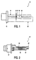
- Fig. 1 is a MPXL lamp designated in its entirety with a Version 12, an outer bulb 14 and a discharge vessel 16 are shown schematically. Two electrodes 18 and 20 are arranged in the discharge vessel, the electrode 20 forms the so-called return pole and via a return wire 22 with not shown Components in the version 12 or in particular a starter is connected.
- the return wire 22 is an annular, the outer bulb and here for Clarification exaggerated high jump antenna 24 connected to the Ignition voltage by equalizing the field structure in the area of the electrode 18 reduced without contacting the discharge vessel 16 or a measurably higher one To cause sodium diffusion into the walls of the discharge vessel 16.
- FIG. 2 shows an MPXL lamp essentially corresponding to the lamp of FIG. 1 shown, the parts corresponding to the parts of Fig. 1 with deleted reference numerals were provided so that a new description can be dispensed with.
- the main difference to the lamp according to FIG. 1 lies in the jump-start antenna 24 ', which in this exemplary embodiment consists of a multiple around the outer bulb 14 ' wound wire, also connected to the return wire 22 '.
Landscapes
- Discharge Lamps And Accessories Thereof (AREA)
- Vessels And Coating Films For Discharge Lamps (AREA)
Abstract
Description
Die Erfindung betrifft eine Gasentladungslampe mit einem von einem Außenkolben umschlossenen Entladungsgefäß und einer um das Entladungsgefäß geführten Starthilfeantenne. Im besonderen betrifft die Erfindung HID(High-Intensity-Discharge)-Lampen wie z.B. High-Pressure-Sodium-Lampen und insbesondere MPXL(Micro-Power-Xenon-Light)-Lampen, wie sie z.B. bei Kraftfahrzeugen eingesetzt werden. Bei diesen speziellen MPXL-Lampen fasst das Entladungsgefäß nur wenige Kubikmilliimeter und ist zur Absorption der bei der Entladung unter anderem entstehenden ultravioletten Strahlung mit einem gas-, insbesondere luftgefüllten und gegen die Umgebungsatmosphäre abgedichteten Außenkolben umgeben.The invention relates to a gas discharge lamp with one of an outer bulb enclosed discharge vessel and a jump-start antenna guided around the discharge vessel. In particular, the invention relates to HID (high-intensity discharge) lamps such as. High-pressure sodium lamps and in particular MPXL (micro power xenon light) lamps, such as be used in motor vehicles. With these special MPXL lamps only hold the discharge vessel for a few cubic millimeters and are for absorption the ultraviolet radiation which arises during the discharge with a gas, in particular air-filled and sealed against the ambient atmosphere Surround the outer bulb.
Bei diesen Lampen besteht das Problem, dass ihre Effektivität hinsichtlich der Lichterzeugung um so höher ist, je höher der Druck des im Entladungsgefäß (das gelegentlich auch Innenkolben oder kurz Brenner genannt wird) vorgesehenen Inertgases, bei MPXL-Lampen also des Xenons, ist, wie z.B. in der GB 1.587.987 beschrieben. Ein höherer Druck des Inertgases bedingt allerdings, dass auch eine höhere Zündspannung zur Zündung der Gasentladung notwendig ist, was wiederum leistungsstärkere und aufwendigere, damit teurere und meist auch baugrößere Zünder erfordert.The problem with these lamps is that they are effective in generating light the higher the pressure in the discharge vessel (the occasionally Inner bulb or burner for short) provided inert gas, in MPXL lamps i.e. the xenon, such as described in GB 1,587,987. A higher one Pressure of the inert gas, however, also means that a higher ignition voltage for ignition gas discharge is necessary, which in turn is more powerful and complex, thus more expensive and usually larger detonators are required.
Es ist nun seit langem bekannt, z.B. aus EP 0 085 487 A2, EP 0 098 014 A2 oder EP 0 474 277 A1, dass die Zündspannung bei HID-Lampen mit Hilfe einer meist als Starthilfeantenne oder kurz nur Antenne bezeichneten Vorrichtung deutlich reduziert werden kann. Die bekannten Antennen werden gerade am Entladungsgefäß entlang oder schleifenförmig um das Entladungsgefäß herum geführt und meist auf ein positives Potential gelegt, so dass sie als eine Art Hilfselektrode wirken und so das elektrische Feld im Innern des Entladungsgefäßes gleichmäßiger verteilt ist. It has long been known, e.g. from EP 0 085 487 A2, EP 0 098 014 A2 or EP 0 474 277 A1 that the ignition voltage in HID lamps with the help of a mostly as Jumper antenna or device referred to as antenna for short, significantly reduced can be. The known antennas are just along the discharge vessel or looped around the discharge vessel and usually on a positive Potential so that they act as a kind of auxiliary electrode and so the electrical field is distributed more evenly inside the discharge vessel.
Allerdings besteht bei den bekannten Antennen das Problem, dass sie nicht ohne weiteres bei MPXL-Lampen eingesetzt werden können, da zum einen deren Dimensionen signifikant kleiner sind als die herkömmlich HID-Lampen, zum anderen werden diese Lampen extrem heiß (am Brenner etwa 600 °C, am Außenkolben rund 400 °C), so dass einfache Antennen unter der Wärmeeinwirkung sich verformen oder gar schmelzen. Auch hat sich gezeigt, dass es bei Lampen, bei denen die Antennen in direktem Kontakt mit oder zumindest unmittelbar an dem Brenner angeordnet sind, beim Betrieb dazu kommt, dass im Brenner in ionisierter Form enthaltenes Natrium verstärkt in oder gar durch die Wandung des Entladungsgefäßes diffundiert, was die Haltbarkeit der Lampen stark beeinträchtigt.However, the problem with the known antennas is that they are not readily MPXL lamps can be used because their dimensions are significant are smaller than the conventional HID lamps, on the other hand these lamps extremely hot (around 600 ° C on the burner, around 400 ° C on the outer bulb), so simple Antennas deform or even melt under the influence of heat. Has also shown that it is in lamps where the antennas are in direct contact with or at least are arranged directly on the burner, during operation that in Burners in ionized form contain sodium reinforced in or even through the wall of the discharge vessel diffuses, which greatly affects the durability of the lamps.
Davon ausgehend liegt der Erfindung die Aufgabe zugrunde, eine Gasentladungslampe der eingangs genannten Art, insbesondere eine MPXL-Lampe anzugeben, bei welcher die positiven Effekte einer Starthilfeantenne auch bei kleinen und kleinsten Entladungsgefäßen ohne hohen Konstruktionsaufwand genutzt werden können, ohne dabei eine verstärkte Natriumdiffusion zu induzieren.Proceeding from this, the invention is based on the object of a gas discharge lamp type mentioned above, in particular an MPXL lamp, in which the positive effects of a jump-start antenna even with small and smallest discharge vessels can be used without a great deal of design effort, without being reinforced To induce sodium diffusion.
Die Aufgabe wird zum einen gelöst von einer Gasentladungslampe mit einem von einem Außenkolben umschlossenen Entladungsgefäß und einer um das Entladungsgefäß geführten Starthilfeantenne, wobei die Starthilfeantenne an der Innen- oder Außenwandung des Außenkolbens vorgesehen ist. Alternativ kann natürlich - basierend auf dem selben erfinderischen Grundgedanken - die Starthilfeantenne auch in den Außenkolben integriert, z.B. beim Blasen oder Gießen des Kolbens eingeschmolzen werden.The problem is solved on the one hand by a gas discharge lamp with one by one Outer bulb enclosed discharge vessel and one around the discharge vessel Jump start antenna, the jump start antenna on the inside or outside wall of the Outer bulb is provided. Alternatively, of course - based on the same inventive concept - the jump start antenna also integrated in the outer bulb, e.g. melted when blowing or pouring the piston.
Die Erfindung beruht also auf der überraschenden Erkenntnis, dass auch mit einer nicht unmittelbar am Entladungsgefäß angeordneten Antenne die Zündspannung erheblich reduziert werden kann, wobei die typische MPXL-Zündspannung von mehr als 10 kV sowohl bei gepulster Zündung, als auch bei Resonanzzündung um bis zu 40% reduziert werden konnte.The invention is based on the surprising finding that even with one The ignition voltage, which is arranged directly on the discharge vessel, considerably increases the ignition voltage can be reduced, with the typical MPXL ignition voltage of more than 10 kV both with pulsed ignition and with resonance ignition reduced by up to 40% could be.
Zudem hat die Erfindung den großen Vorteil, dass auf die bei den bekannten Antennen teilweise notwendige aufwendige Trag- und Stützkonstruktion verzichtet werden kann, da der Außenkolben als Träger dient. In addition, the invention has the great advantage that the known antennas partially necessary complex support and support structure can be dispensed with, because the outer bulb serves as a carrier.
Als weiterer positiver Effekt hat sich gezeigt, dass erfindungsgemäß ausgestattete MPXL-Lampen insbesondere im Hochfrequenzbetrieb deutlich seltener zu Fehlzündungen neigen, was seinen Grund in der Tatsache hat, dass die Antenne parasitäre Entladungserscheinungen verhindert und die für den HF-Betrieb typischen Äquipotentiallinien näher an das Entladungsgefäß bindet.A further positive effect has been shown that MPXL lamps equipped according to the invention especially in high-frequency operation, they tend to misfire much less often, which is due to the fact that the antenna has parasitic discharge phenomena prevented and the equipotential lines typical for HF operation closer to Discharge vessel binds.
Die Starthilfeantenne kann vorteilhaft in einer dem jeweiligen Anwendungsfall optimal angepassten Weise ausgebildet werden, also z.B. mittels eines Drahtes aus elektrisch gut leitendern Material, der ein- oder mehrfach um den Außenkolben gewickelt wird, oder mittels eines auf der Außen- oder Innenseite des Außenkolbens angeordneten metallischen Ringes. Dabei sind die auf der Außenseite des Kolbens vorgesehenen Antennen besonders einfach zu realisieren und können insbesondere auch bei fertigen oder zumindest fertig konstruierten MPXL-Lampen problemlos nachgerüstet werden, was ein großer Vorteil ist, da die Konstruktion einer MPXL-Lampe sehr aufwendig ist und das nachträgliche Einkonstruieren der bislang bekannten Antennen einen erheblichen Aufwand darstellte. Auch zeigen einige Lampen erst im Praxistest mit bestimmten Zündern in der Kalt- und/oder Heißzündphase eine gewisse Zündunwilligkeit. Bislang wurden dann bei der Produktion die ursprünglich vorgesehenen Zünder durch leistungsstärkere und damit in der Regel teurere Zünder ersetzt. Erfindungsgemäß kann nun statt eines leistungsstärkeren Zünders ohne konstruktiven Mehraufwand die Zündspannung durch eine am Außenkolben angebrachte einfache Starthilfeantenne reduziert werden.The starting aid antenna can advantageously be optimal in a particular application adapted manner, e.g. using a wire made of electrically good conductive material that is wrapped one or more times around the outer bulb, or by means of a metallic arranged on the outside or inside of the outer bulb Ring. The antennas provided on the outside of the piston are special easy to implement and can be used in particular when finished or at least finished constructed MPXL lamps can be easily retrofitted, which is a great advantage because the construction of an MPXL lamp is very complex and the subsequent installation the previously known antennas represented a considerable effort. Also show some lamps only in the practical test with certain igniters in the cold and / or Hot ignition phase a certain unwillingness to ignite. So far, then in production the originally intended detonators by more powerful and therefore usually more expensive detonators replaced. According to the invention, instead of a more powerful igniter without additional design effort, the ignition voltage by a on the outer bulb attached simple jump starter antenna can be reduced.
Für bestimmte Lampen kann in zweckmäßiger Weiterbildung der Erfindung die Starthilfeantenne als sogenannte Plasmaantenne mit einer gasgefüllten ringförmigen Röhre ausführt werden, wobei in der Röhre dann eine Elektrode, bei der es sich sowohl um eine kapazitive als auch um eine direkte Elektrode handeln kann, angeordnet ist. Durch Anlegen einer Spannung an diese Elektrode wird in der Röhre eine Glimmentladung hervorgerufen, die dieselbe Wirkung hat, wie ein Ring, eine Spule oder eine Schicht aus leitendem Material. For certain lamps, the starting aid antenna can be used in an expedient development of the invention as a so-called plasma antenna with a gas-filled annular tube be an electrode in the tube, which is both a capacitive and can also be a direct electrode. By creating one Voltage on this electrode causes a glow discharge in the tube has the same effect as a ring, a coil or a layer of conductive material.
Auf die Starthilfeantenne kann in verschiedener Weise ein Potential gelegt werden. Als besonders zweckmäßig und einfach hat es sich jedoch erwiesen, die Starthilfeantenne mit einem der im Entladungsgefäß vorgesehenen Pole, insbesondere mit dem Rückführpol zu verbinden.A potential can be put on the jump start antenna in various ways. As However, it has proven particularly practical and simple to use the jump-start antenna one of the poles provided in the discharge vessel, in particular with the return pole connect.
Weitere Einzelheiten und Vorteile der Erfindung ergeben sich aus der nachfolgenden Beschreibung zweier Ausführungsbeispiele in Verbindung mit der Zeichnung. Es zeigen:
- Fig. 1
- eine Prinzipskizze einer MPXL-Lampe mit einer ringartigen Starthilfeantenne auf dem Außenkolben und
- Fig. 2
- eine Prinzipskizze einer anderen MPXL-Lampe mit einem zur Bildung einer Starthilfeantenne mehrfach um den Außenkolben gewickelten Draht.
- Fig. 1
- a schematic diagram of an MPXL lamp with a ring-like jump start antenna on the outer bulb and
- Fig. 2
- a schematic diagram of another MPXL lamp with a wire wound several times around the outer bulb to form a jump-start antenna.
In der Fig. 1 ist einer in ihrer Gesamtheit mit 10 bezeichnete MPXL-Lampe mit einer
Fassung 12, einem Außenkolben 14 und einem Entladungsgefäß 16 schematisch gezeigt.
In dem Entladungsgefäß sind zwei Elektroden 18 und 20 angeordnet, wobei die Elektrode
20 den sog. Rückführpol bildet und über einen Rückführdraht 22 mit nicht weiter dargestellten
Bauteilen in der Fassung 12 bzw. insbesondere einem Starter verbunden ist.In Fig. 1 is a MPXL lamp designated in its entirety with a
An den Rückführdraht 22 ist eine ringförmige, den Außenkolben umfassende und hier zur
Verdeutlichung übertrieben hoch dargestellte Starthilfeantenne 24 angeschlossen, die die
Zündspannung durch Vergleichmäßigung der Feldstruktur im Bereich der Elektrode 18
reduziert, ohne mit dem Entladungsgefäß 16 in Kontakt zu treten oder eine messbar höhere
Natriumdiffusion in die Wandungen des Entladungsgefäßes 16 hinein zu bewirken.On the
In der Figur 2 ist eine im wesentlichen der Lampe der Fig. 1 entsprechende MPXL-Lampe gezeigt, wobei die den Teilen der Fig. 1 entsprechenden Teile mit gestrichenen Bezugszeichen versehen wurden, so dass auf eine erneute Beschreibung verzichtet werden kann. FIG. 2 shows an MPXL lamp essentially corresponding to the lamp of FIG. 1 shown, the parts corresponding to the parts of Fig. 1 with deleted reference numerals were provided so that a new description can be dispensed with.
Der wesentliche Unterschied zur Lampe gemäß Fig. 1 liegt in der Starthilfeantenne 24', die bei diesem Ausführungsbeispiel von einem mehrfach um den Außenkolben 14' gewickelten, ebenfalls mit dem Rückführdraht 22' verbundenen Draht gebildet wird.The main difference to the lamp according to FIG. 1 lies in the jump-start antenna 24 ', which in this exemplary embodiment consists of a multiple around the outer bulb 14 ' wound wire, also connected to the return wire 22 '.
Im Rahmen des Erfindungsgedankens sind zahlreiche Abwandlungen und Weiterbildungen möglich, die sich zum Beispiel auf die Anzahl und die Anordnung der Antennen beziehen. So ist es zum Beispiel möglich, statt eines Ringes auch zwei oder mehr Ringe auf der Außen- und/oder der Innenseite des Außenkolbens und/oder in den Außenkolben eingelassen vorzusehen. Statt eines Drahtes, eines Ringes oder einer Plasmaantenne kann auch auf oder in dem Außenkolben eine Schicht aus leitendem Material auf- bzw. eingebracht sein. Erfindungswesentlich ist jedenfalls, dass bei einer Lampe mit einem Entladungsgefäß und einem das Entladungsgefäß umgebenden Außenkolben die Starthilfeantenne im oder am Außenkolben angebracht wird.Numerous modifications and further developments are within the scope of the inventive concept possible, for example, based on the number and arrangement of antennas Respectively. For example, it is possible to have two or more rings instead of one ring the outside and / or the inside of the outer bulb and / or in the outer bulb recessed to provide. Instead of a wire, a ring or a plasma antenna a layer of conductive material is also applied or introduced on or in the outer bulb his. In any case, it is essential to the invention that in the case of a lamp with a discharge vessel and an outer bulb surrounding the discharge vessel, the jump-start antenna is attached in or on the outer bulb.
Claims (10)
gekennzeichnet durch eine um das Entladungsgefäß geführte Starthilfeantenne, die an dem Außenkolben, vorzugsweise an der Innen- oder Außenwandung des Außenkolbens vorgesehen ist.Gas discharge lamp with a discharge vessel enclosed by an outer bulb,
characterized by a starting aid antenna guided around the discharge vessel, which is provided on the outer bulb, preferably on the inner or outer wall of the outer bulb.
dadurch gekennzeichnet,
dass die Starthilfeantenne in den Außenkolben integriert ist.Gas discharge lamp with a discharge vessel enclosed by an outer bulb and a starting aid antenna guided around the discharge vessel
characterized,
that the jump starter antenna is integrated in the outer bulb.
dadurch gekennzeichnet,
dass die Starthilfeantenne mittels eines Drahtes aus elektrisch gut leitendern Material gebildet wird.Gas discharge lamp according to claim 1 or 2,
characterized,
that the jump-start antenna is formed by means of a wire made of electrically well-conductive material.
dadurch gekennzeichnet,
dass der Draht derart ausgeformt ist, dass er das Entladungsgefäß nach Art einer Spule vorzugsweise mehrfach kontaktlos umschließt.Gas discharge lamp according to claim 3,
characterized,
that the wire is shaped in such a way that it encloses the discharge vessel in the manner of a coil, preferably multiple times without contact.
dadurch gekennzeichnet,
dass die Starthilfeantenne mittels wenigstens eines metallischen, das Entladungsgefäß berührungslos umschließenden Ringes gebildet wird. Gas discharge lamp according to claim 1 or 2,
characterized,
that the starting aid antenna is formed by means of at least one metallic ring which surrounds the discharge vessel without contact.
dadurch gekennzeichnet,
dass die Starthilfeantenne eine Plasmaantenne mit einer gasgefüllten ringförmigen Röhre ist.Gas discharge lamp according to claim 1 or 2,
characterized,
that the jump start antenna is a plasma antenna with a gas-filled annular tube.
dadurch gekennzeichnet,
dass die Starthilfeantenne mittels einer Schicht aus elektrisch leitendem Material auf oder in dem Außenkolben gebildet ist.Gas discharge lamp according to claim 1 or 2,
characterized,
that the starting aid antenna is formed on or in the outer bulb by means of a layer of electrically conductive material.
dadurch gekennzeichnet,
dass die Starthilfeantenne mit einem der im Entladungsgefäß vorgesehenen Pole, insbesondere mit dem Rückführpol verbunden ist.Gas discharge lamp according to one of claims 1 to 7,
characterized,
that the starting aid antenna is connected to one of the poles provided in the discharge vessel, in particular to the return pole.
dadurch gekennzeichnet,
dass die Gasentladungslampe eine HID (High-Intensity-Discharge)-Lampe ist.Gas discharge lamp according to one of claims 1 to 8,
characterized,
that the gas discharge lamp is a HID (high-intensity discharge) lamp.
dadurch gekennzeichnet,
dass die Gasentladungslampe eine MPXL (Micro-Power-Xenon-Light)-Lampe ist.Gas discharge lamp according to one of claims 1 to 9,
characterized,
that the gas discharge lamp is an MPXL (Micro Power Xenon Light) lamp.
Applications Claiming Priority (2)
| Application Number | Priority Date | Filing Date | Title |
|---|---|---|---|
| DE19933023 | 1999-07-15 | ||
| DE19933023A DE19933023A1 (en) | 1999-07-15 | 1999-07-15 | Gas discharge lamp |
Publications (2)
| Publication Number | Publication Date |
|---|---|
| EP1069596A2 true EP1069596A2 (en) | 2001-01-17 |
| EP1069596A3 EP1069596A3 (en) | 2001-02-14 |
Family
ID=7914785
Family Applications (1)
| Application Number | Title | Priority Date | Filing Date |
|---|---|---|---|
| EP00202407A Withdrawn EP1069596A3 (en) | 1999-07-15 | 2000-07-06 | Discharge lamp with starting aid |
Country Status (6)
| Country | Link |
|---|---|
| US (1) | US6674239B1 (en) |
| EP (1) | EP1069596A3 (en) |
| JP (1) | JP2001043831A (en) |
| KR (1) | KR20010049771A (en) |
| CN (1) | CN1284737A (en) |
| DE (1) | DE19933023A1 (en) |
Cited By (5)
| Publication number | Priority date | Publication date | Assignee | Title |
|---|---|---|---|---|
| US7884549B2 (en) | 2006-07-07 | 2011-02-08 | Koninklijke Philips Electronics N.V. | Gas-discharge lamp |
| US8659225B2 (en) | 2011-10-18 | 2014-02-25 | General Electric Company | High intensity discharge lamp with crown and foil ignition aid |
| US8674591B2 (en) | 2006-07-07 | 2014-03-18 | Koninklijke Philips N.V. | Gas discharge lamp with outer cavity |
| US8766518B2 (en) | 2011-07-08 | 2014-07-01 | General Electric Company | High intensity discharge lamp with ignition aid |
| US9666425B2 (en) | 2005-01-03 | 2017-05-30 | Koninklijke Philips N.V. | Gas discharge lamp |
Families Citing this family (11)
| Publication number | Priority date | Publication date | Assignee | Title |
|---|---|---|---|---|
| JP3916887B2 (en) * | 2001-06-05 | 2007-05-23 | 株式会社小糸製作所 | Lighting device |
| US8076852B2 (en) | 2003-04-09 | 2011-12-13 | Panasonic Corporation | High-pressure discharge lamp, lighting method and lighting device for high-pressure discharge lamp, high-pressure discharge lamp device, and lamp unit, image display device and headlight device |
| EP1665332A2 (en) * | 2003-09-17 | 2006-06-07 | Koninklijke Philips Electronics N.V. | Gas discharge lamp |
| US7417377B2 (en) * | 2003-09-18 | 2008-08-26 | Koninklijke Philips Electronics N.V. | Blended light lamp |
| US7038383B2 (en) * | 2004-09-27 | 2006-05-02 | Osram Sylvania Inc. | Ignition aid for high intensity discharge lamp |
| DE102005003129A1 (en) * | 2005-01-21 | 2006-07-27 | Patent-Treuhand-Gesellschaft für elektrische Glühlampen mbH | High pressure discharge lamp |
| JP2010530606A (en) * | 2007-06-21 | 2010-09-09 | コーニンクレッカ フィリップス エレクトロニクス エヌ ヴィ | High pressure discharge lamp with starter antenna |
| JP2010262740A (en) * | 2009-04-30 | 2010-11-18 | Harison Toshiba Lighting Corp | Discharge lamp |
| DE102011077487A1 (en) * | 2011-06-14 | 2012-12-20 | Osram Ag | High pressure discharge lamp with ignition aid |
| US9927094B2 (en) * | 2012-01-17 | 2018-03-27 | Kla-Tencor Corporation | Plasma cell for providing VUV filtering in a laser-sustained plasma light source |
| CN104810236B (en) * | 2015-04-10 | 2017-07-28 | 南京高新经纬电气有限公司 | High-pressure mercury lamp and its ceramic auxiliary actuator and startup method |
Family Cites Families (10)
| Publication number | Priority date | Publication date | Assignee | Title |
|---|---|---|---|---|
| US3828214A (en) * | 1973-08-30 | 1974-08-06 | Gte Sylvania Inc | Plasma enshrouded electric discharge device |
| US3900753A (en) * | 1974-05-23 | 1975-08-19 | Gte Sylvania Inc | High pressure sodium vapor lamp having low starting voltage |
| DE2948996A1 (en) * | 1979-12-05 | 1981-06-11 | Heimann Gmbh, 6200 Wiesbaden | Gas discharge flash tube with ignition electrodes - has metallic layer on outer surface of tube with supply lead |
| JPS57119446A (en) * | 1981-01-19 | 1982-07-24 | Mitsubishi Electric Corp | High pressure electric-discharge lamp |
| JPS57138770A (en) * | 1981-02-20 | 1982-08-27 | Mitsubishi Electric Corp | High pressure electric-discharge lamp |
| DE3809623A1 (en) * | 1988-03-22 | 1989-10-05 | Patent Treuhand Ges Fuer Elektrische Gluehlampen Mbh | High pressure discharge lamp of low power |
| DE19624243A1 (en) * | 1996-06-18 | 1998-01-02 | Bosch Gmbh Robert | Discharge lamp esp for motor vehicle head-light |
| JPH10320026A (en) * | 1997-05-20 | 1998-12-04 | Mitsubishi Electric Corp | Numerical control device and method |
| US6201348B1 (en) * | 1998-02-20 | 2001-03-13 | Osram Sylvania Inc. | Capacitive coupling starting aid for metal halide lamp |
| US6198223B1 (en) * | 1998-06-24 | 2001-03-06 | Osram Sylvania Inc. | Capacitive glow starting of ceramic high intensity discharge devices |
-
1999
- 1999-07-15 DE DE19933023A patent/DE19933023A1/en not_active Withdrawn
-
2000
- 2000-07-06 EP EP00202407A patent/EP1069596A3/en not_active Withdrawn
- 2000-07-12 CN CN00126267.XA patent/CN1284737A/en active Pending
- 2000-07-13 KR KR1020000040055A patent/KR20010049771A/en not_active Withdrawn
- 2000-07-13 JP JP2000212223A patent/JP2001043831A/en active Pending
- 2000-07-14 US US09/616,734 patent/US6674239B1/en not_active Expired - Fee Related
Cited By (5)
| Publication number | Priority date | Publication date | Assignee | Title |
|---|---|---|---|---|
| US9666425B2 (en) | 2005-01-03 | 2017-05-30 | Koninklijke Philips N.V. | Gas discharge lamp |
| US7884549B2 (en) | 2006-07-07 | 2011-02-08 | Koninklijke Philips Electronics N.V. | Gas-discharge lamp |
| US8674591B2 (en) | 2006-07-07 | 2014-03-18 | Koninklijke Philips N.V. | Gas discharge lamp with outer cavity |
| US8766518B2 (en) | 2011-07-08 | 2014-07-01 | General Electric Company | High intensity discharge lamp with ignition aid |
| US8659225B2 (en) | 2011-10-18 | 2014-02-25 | General Electric Company | High intensity discharge lamp with crown and foil ignition aid |
Also Published As
| Publication number | Publication date |
|---|---|
| US6674239B1 (en) | 2004-01-06 |
| CN1284737A (en) | 2001-02-21 |
| JP2001043831A (en) | 2001-02-16 |
| EP1069596A3 (en) | 2001-02-14 |
| KR20010049771A (en) | 2001-06-15 |
| DE19933023A1 (en) | 2001-01-18 |
Similar Documents
| Publication | Publication Date | Title |
|---|---|---|
| EP1069596A2 (en) | Discharge lamp with starting aid | |
| EP1632985B1 (en) | High-pressure discharge lampe | |
| DE2654715A1 (en) | HIGH PRESSURE DISCHARGE LAMP WITH STARTING CIRCUIT INCLUDED IN IT | |
| DE69903782T2 (en) | UNIT WITH A SHORT BEND DISCHARGE LAMP WITH STARTING ANTENNA | |
| EP1984936B1 (en) | High-pressure discharge lamp | |
| DE69018133T2 (en) | Luminous body for an electrodeless high-performance discharge lamp. | |
| EP0802561A1 (en) | Halogen lamp | |
| WO2001073817A1 (en) | Gas discharge lamp with ignition assisting electrodes, especially for automobile headlights | |
| DE2332274A1 (en) | HIGH PRESSURE GAS DISCHARGE LAMP | |
| DE69903364T2 (en) | Ignition aid for high intensity discharge lamp | |
| DE19624243A1 (en) | Discharge lamp esp for motor vehicle head-light | |
| EP1276137B1 (en) | Dielectric-barrier discharge lamp with starting aid | |
| DE10331510B4 (en) | Short arc discharge lamp and light source device | |
| WO2012045366A1 (en) | High-pressure discharge lamp having a capacitive ignition aid | |
| EP2499651B1 (en) | High-pressure discharge lamp having a single socket | |
| DE19947242A1 (en) | High pressure discharge lamp | |
| WO2008135084A1 (en) | High-pressure discharge lamp having a starting aid | |
| EP2009668B1 (en) | Discharge lamp socketed on one side | |
| DE102015101804B4 (en) | Flash lamp arrangement with capacitive coupling between ignition electrode and ignition electrode lead or corresponding flash lamp bearing arrangement | |
| DE212010000115U1 (en) | High pressure discharge lamp with ignition aid | |
| WO2012007405A2 (en) | High-pressure discharge lamp with ignition aid | |
| DE102004043636A1 (en) | Mercury-free halogen metal-vapor high-pressure discharge lamp for vehicle headlight, has discharge vessel provided partially with coating, so that capacitive coupling is produced between coating and electrode and/or power supply lines | |
| DE19640666A1 (en) | Discharge lamp esp. for vehicle illumination units with base and filament | |
| WO2011018118A1 (en) | High-pressure discharge lamp having a starting aid | |
| DE202010017945U1 (en) | High pressure discharge lamp with capacitive starting aid |
Legal Events
| Date | Code | Title | Description |
|---|---|---|---|
| PUAI | Public reference made under article 153(3) epc to a published international application that has entered the european phase |
Free format text: ORIGINAL CODE: 0009012 |
|
| PUAL | Search report despatched |
Free format text: ORIGINAL CODE: 0009013 |
|
| AK | Designated contracting states |
Kind code of ref document: A2 Designated state(s): DE FR GB IT |
|
| AX | Request for extension of the european patent |
Free format text: AL;LT;LV;MK;RO;SI |
|
| AK | Designated contracting states |
Kind code of ref document: A3 Designated state(s): AT BE CH CY DE DK ES FI FR GB GR IE IT LI LU MC NL PT SE |
|
| AX | Request for extension of the european patent |
Free format text: AL;LT;LV;MK;RO;SI |
|
| 17P | Request for examination filed |
Effective date: 20010814 |
|
| AKX | Designation fees paid |
Free format text: DE FR GB IT |
|
| RAP1 | Party data changed (applicant data changed or rights of an application transferred) |
Owner name: KONINKLIJKE PHILIPS ELECTRONICS N.V. Owner name: PHILIPS CORPORATE INTELLECTUAL PROPERTY GMBH |
|
| 17Q | First examination report despatched |
Effective date: 20030320 |
|
| RAP1 | Party data changed (applicant data changed or rights of an application transferred) |
Owner name: PHILIPS INTELLECTUAL PROPERTY & STANDARDS GMBH Owner name: KONINKLIJKE PHILIPS ELECTRONICS N.V. |
|
| STAA | Information on the status of an ep patent application or granted ep patent |
Free format text: STATUS: THE APPLICATION IS DEEMED TO BE WITHDRAWN |
|
| 18D | Application deemed to be withdrawn |
Effective date: 20031001 |