EP1069575A1 - Procédé de démontage pour générateur de champ magnétique et son procédé de recyclage - Google Patents
Procédé de démontage pour générateur de champ magnétique et son procédé de recyclage Download PDFInfo
- Publication number
- EP1069575A1 EP1069575A1 EP00114873A EP00114873A EP1069575A1 EP 1069575 A1 EP1069575 A1 EP 1069575A1 EP 00114873 A EP00114873 A EP 00114873A EP 00114873 A EP00114873 A EP 00114873A EP 1069575 A1 EP1069575 A1 EP 1069575A1
- Authority
- EP
- European Patent Office
- Prior art keywords
- magnetic field
- neodymium magnets
- field generator
- neodymium
- adhesive
- Prior art date
- Legal status (The legal status is an assumption and is not a legal conclusion. Google has not performed a legal analysis and makes no representation as to the accuracy of the status listed.)
- Granted
Links
Images


Classifications
-
- B—PERFORMING OPERATIONS; TRANSPORTING
- B09—DISPOSAL OF SOLID WASTE; RECLAMATION OF CONTAMINATED SOIL
- B09B—DISPOSAL OF SOLID WASTE NOT OTHERWISE PROVIDED FOR
- B09B3/00—Destroying solid waste or transforming solid waste into something useful or harmless
- B09B3/40—Destroying solid waste or transforming solid waste into something useful or harmless involving thermal treatment, e.g. evaporation
-
- B—PERFORMING OPERATIONS; TRANSPORTING
- B09—DISPOSAL OF SOLID WASTE; RECLAMATION OF CONTAMINATED SOIL
- B09B—DISPOSAL OF SOLID WASTE NOT OTHERWISE PROVIDED FOR
- B09B3/00—Destroying solid waste or transforming solid waste into something useful or harmless
- B09B3/30—Destroying solid waste or transforming solid waste into something useful or harmless involving mechanical treatment
- B09B3/35—Shredding, crushing or cutting
-
- G—PHYSICS
- G01—MEASURING; TESTING
- G01R—MEASURING ELECTRIC VARIABLES; MEASURING MAGNETIC VARIABLES
- G01R33/00—Arrangements or instruments for measuring magnetic variables
- G01R33/20—Arrangements or instruments for measuring magnetic variables involving magnetic resonance
- G01R33/28—Details of apparatus provided for in groups G01R33/44 - G01R33/64
- G01R33/38—Systems for generation, homogenisation or stabilisation of the main or gradient magnetic field
- G01R33/383—Systems for generation, homogenisation or stabilisation of the main or gradient magnetic field using permanent magnets
-
- H—ELECTRICITY
- H01—ELECTRIC ELEMENTS
- H01F—MAGNETS; INDUCTANCES; TRANSFORMERS; SELECTION OF MATERIALS FOR THEIR MAGNETIC PROPERTIES
- H01F13/00—Apparatus or processes for magnetising or demagnetising
- H01F13/006—Methods and devices for demagnetising of magnetic bodies, e.g. workpieces, sheet material
-
- H—ELECTRICITY
- H01—ELECTRIC ELEMENTS
- H01F—MAGNETS; INDUCTANCES; TRANSFORMERS; SELECTION OF MATERIALS FOR THEIR MAGNETIC PROPERTIES
- H01F7/00—Magnets
- H01F7/02—Permanent magnets [PM]
- H01F7/0273—Magnetic circuits with PM for magnetic field generation
- H01F7/0278—Magnetic circuits with PM for magnetic field generation for generating uniform fields, focusing, deflecting electrically charged particles
-
- H—ELECTRICITY
- H01—ELECTRIC ELEMENTS
- H01F—MAGNETS; INDUCTANCES; TRANSFORMERS; SELECTION OF MATERIALS FOR THEIR MAGNETIC PROPERTIES
- H01F7/00—Magnets
- H01F7/02—Permanent magnets [PM]
- H01F7/04—Means for releasing the attractive force
-
- Y—GENERAL TAGGING OF NEW TECHNOLOGICAL DEVELOPMENTS; GENERAL TAGGING OF CROSS-SECTIONAL TECHNOLOGIES SPANNING OVER SEVERAL SECTIONS OF THE IPC; TECHNICAL SUBJECTS COVERED BY FORMER USPC CROSS-REFERENCE ART COLLECTIONS [XRACs] AND DIGESTS
- Y10—TECHNICAL SUBJECTS COVERED BY FORMER USPC
- Y10T—TECHNICAL SUBJECTS COVERED BY FORMER US CLASSIFICATION
- Y10T29/00—Metal working
- Y10T29/49—Method of mechanical manufacture
- Y10T29/49002—Electrical device making
- Y10T29/49009—Dynamoelectric machine
-
- Y—GENERAL TAGGING OF NEW TECHNOLOGICAL DEVELOPMENTS; GENERAL TAGGING OF CROSS-SECTIONAL TECHNOLOGIES SPANNING OVER SEVERAL SECTIONS OF THE IPC; TECHNICAL SUBJECTS COVERED BY FORMER USPC CROSS-REFERENCE ART COLLECTIONS [XRACs] AND DIGESTS
- Y10—TECHNICAL SUBJECTS COVERED BY FORMER USPC
- Y10T—TECHNICAL SUBJECTS COVERED BY FORMER US CLASSIFICATION
- Y10T29/00—Metal working
- Y10T29/49—Method of mechanical manufacture
- Y10T29/49002—Electrical device making
- Y10T29/4902—Electromagnet, transformer or inductor
- Y10T29/49075—Electromagnet, transformer or inductor including permanent magnet or core
-
- Y—GENERAL TAGGING OF NEW TECHNOLOGICAL DEVELOPMENTS; GENERAL TAGGING OF CROSS-SECTIONAL TECHNOLOGIES SPANNING OVER SEVERAL SECTIONS OF THE IPC; TECHNICAL SUBJECTS COVERED BY FORMER USPC CROSS-REFERENCE ART COLLECTIONS [XRACs] AND DIGESTS
- Y10—TECHNICAL SUBJECTS COVERED BY FORMER USPC
- Y10T—TECHNICAL SUBJECTS COVERED BY FORMER US CLASSIFICATION
- Y10T29/00—Metal working
- Y10T29/49—Method of mechanical manufacture
- Y10T29/49751—Scrap recovering or utilizing
- Y10T29/49753—Metalworking to consolidate scrap
Definitions
- the present invention relates to a dismantling method and a recycling method for a magnetic field generator, and more specifically to a dismantling method and a recycling method for a magnetic field generator comprising neodymium magnets and used in a large MRI apparatus capable of scanning a human body.
- neodymium magnet which is a sintered body
- Size of the neodymium magnet, which is a sintered body, is limited.
- a plurality of neodymium magnets are fixed to a plate yoke by an adhesive.
- a method for dismantling such a magnetic field generator can be as follows: Specifically, screws connecting the plate yokes to column yokes are loosened, then the magnetic field generator is suspended by a crane, and disassembled. Each of the plate yokes is then bathed in a drum filled with solvent for melting the adhesive, and the neodymium magnets fixed to the plate yokes are taken out.
- the neodymium magnets as magnetized, have a very strong magnetism. Therefore, according to the above-mentioned method, it is dangerous because the neodymium magnets will be thrown out of the drum by strong repelling force among the neodymium magnets once the adhesive loses its adhering strength. Another potential danger is that a worker's hand can be caught between two neodymium magnets for example, by strong magnetic attraction, when one of the neodymium magnets is pulled off from another.
- the neodymium magnet is a sintered body which is fragile. Thus, once the adhesive loses its adhering strength, if the magnet is thrown by a magnetic repelling force acting among the neodymium magnets and hits something, the magnet will be chipped.
- neodymium magnet hits another neodymium magnet or the plate yoke, a spark will be generated, which may cause fire or explosion accident.
- the neodymium magnets are demagnetized by applying demagnetizing magnetic field at the time of dismantling the magnetic field generator.
- the magnetic field generator for MRI apparatus is large, and therefore demagnetizing operation, in which a strong and large magnetic field must be generated, is difficult.
- a large demagnetizing equipment is not realistic due to a high cost.
- each of permanent magnets is first magnetized, then measured for its magnetic characteristic, then heated to demagnetize, and at a time of assembly, each of the magnets is re-magnetized in accordance with its magnetic characteristic for assembly into a magnet body.
- this method is for appropriately disposing the permanent magnets, and nothing has been disclosed for a method for dismantling or recycling the large magnetic field generator.
- a dismantling method for a magnetic field generator comprising a plate yoke, and a permanent magnet provided on the plate yoke and including a plurality of neodymium magnets bonded together by an adhesive, wherein the magnetic field generator is heated at a temperature of 200°C ⁇ 1000°C.
- the heating temperature of the magnetic field generator is lower than 200 °C , the neodymium magnets cannot be sufficiently demagnetized and cannot be taken out safely. Further, the adhesive has reversibility up to 200 °C, and therefore if the heating temperature is lower than 200°C, then adhering strength will come back when the adhesive is cooled thereafter. On the other hand, if the heating temperature exceeds 1000°C, structure of the neodymium magnets is altered and its magnetic characteristic is deteriorated, making difficult to reuse the collected neodymium magnets. Therefore, by heating the magnetic field generator at a temperature of 200 °C - 1000 °C, the neodymium magnets are sufficiently demagnetized and the adhering strength of the adhesive is reduced. As a result, the neodymium magnets can be taken out safely, and the magnetic field generator can be dismantled safely. Further, the simple heating operation makes possible to reduce cost.
- the magnetic field generator further comprises a column yoke connected to the plate yoke.
- the as-magnetized neodymium magnets are very dangerous, but by heating the magnetic field generator in a state in which the column yoke is connected to the plate yoke, handling of the magnetic field generator at the time of dismantling becomes easier.
- the heating temperature of the magnetic field generator is 200 °C ⁇ 400 °C . Due to a characteristic of the neodymium magnets, aging becomes necessary if the heating temperature exceeds 400°C. Thus, by heating at a temperature not higher than 400°C, it becomes possible to reuse the neodymium magnets by only re-magnetizing the heated neodymium magnets without performing the aging operation.
- the heating temperature of the magnetic field generator is 200°C ⁇ 350°C, and at least one of the neodymium magnets is removed by first demagnetizing the neodymium magnet and then removing the adhesive.
- the neodymium magnets are demagnetized, the adhesive is degraded, and the adhering strength of the adhesive is reduced.
- the neodymium magnets can be taken out safely. Further, since surfaces of the neodymium magnets are not severely deteriorated, the neodymium magnets can be reused easily.
- the heating temperature of the magnetic field generator is 350°C ⁇ 1000°C, and at least one of the neodymium magnets is removed by carbonizing the adhesive.
- the adhesive is carbonized to lose the adhering strength and the neodymium magnets lose the magnetism almost completely. Therefore, the removal and handling of the neodymium magnets becomes easy.
- the adhesive is an acrylic adhesive.
- the acrylic adhesive has a high adhering strength under a room temperature, yet the adhering strength is reduced due to thermal degradation or carbonization if heated at a temperature exceeding 200°C. Therefore, the removal of the neodymium magnets becomes easy if the acrylic adhesive is used as the adhesive.
- the neodymium magnets are three-element neodymium magnets having a R-Fe-B (R is rare earth element) composition.
- the three-element neodymium magnet as compared to a four-element neodymium magnet which includes Co, has a lower magnetic flux density and coercive force at a high temperature range, starts losing the magnetic force at a lower temperature, and has a greater demagnetizing rate. Therefore, if the three-element neodymium magnets are used, desired demagnetization can be achieved easily to the neodymium magnets, making the magnetic field generator suitable for recycling by heating.
- magnetic poles of the neodymium magnets are oriented in the same direction. If the magnetic poles of the neodymium magnets are oriented in the same direction, the magnetism generated becomes more intense. However, according to the present invention, the neodymium magnets can be collected safely even under such a situation.
- a recycling method for a magnetic field generator comprising a plate yoke, and a permanent magnet provided on the plate yoke and including a plurality of neodymium magnets bonded together by an adhesive, wherein the magnetic field generator is heated to 200°C ⁇ 1000°C, then at least one of the neodymium magnets is removed, and a surface of the removed neodymium magnet is polished for reusing the neodymium magnet.
- the surfaces of the removed neodymium magnets By polishing the surfaces of the removed neodymium magnets, the surfaces are cleaned and adhesion necessary for re-bonding the neodymium magnets are recovered, enabling the recycling of the neodymium magnets.
- a recycling method for a magnetic field generator comprising a plate yoke, and a permanent magnet provided on the plate yoke and including a plurality of neodymium magnets bonded together by an adhesive, wherein the magnetic field generator is heated to 200°C ⁇ 1000°C, then at least one of the neodymium magnets is removed, and the removed neodymium magnet is re-aged for reusing.
- the characteristic of the neodymium magnets can be reliably reestablished, enabling smooth recycling of the neodymium magnets.
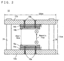
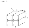
- Fig. 1 and Fig. 2 show an example of a magnetic field generator 10 to which the present invention is applied.
- the magnetic field generator 10 is a magnetic field generator for an MRI apparatus, and is now shown without electric components, being primarily made of magnetic components only.
- the magnetic field generator 10 comprises a pair of plate yokes 12a, 12b opposed to each other with a space in between.
- Each of the plate yokes 12a, 12b has a surface opposed to that of the other plate yoke.
- the surfaces are provided with permanent magnets 14a, 14b respectively, and pole pieces 16a, 16b disposed thereon respectively.
- Pole pieces 16a, 16b are fixed onto the permanent magnets 14a, 14b by a plurality of pole piece fixing bolts 18a, 18b penetrating the plate yokes 12a, 12b respectively.
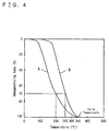
- Each of the permanent magnets 14a, 14b is made of a plurality of magnet blocks 20.
- the magnetic block 20 is formed by a plurality of neodymium magnets 22, each being a rectangular parallelepiped of a size 55 mm x 50 mm x 50 mm for example, bonded into a rectangular parallelepiped with magnetic poles oriented in the same direction.
- the permanent magnets 14a, 14b having a consistent magnetic characteristic can be obtained.
- an intense magnetic field of 0.2 T ⁇ 0.3 T can be obtained between the pole pieces 16a, 16b.
- the neodymium magnets 22 are pulling each other in the vertical directions, but repelling against each other in the horizontal directions because faces of a same pole come side by side.
- the neodymium magnet 22 is, for example, a three-element neodymium magnet having an R-Fe-B composition (31 wt% of Nd, 1.0 wt% of B, with the rest being Fe including such elements by an amount not greater than 0.3 wt% as Al, Cu and others) disclosed in the U.S. Patent No. 4,770,723.
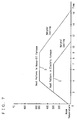
- a thermal demagnetizing curve of this three-element neodymium magnet is shown as curve A in Fig. 4.
- a thermal demagnetizing curve of a four-element neodymium magnet further including 0.9 wt% of Co is shown as curve B.
- the three-element neodymium magnet has a lower heat resistance than the four-element neodymium magnet, beginning to lose magnetism at a lower temperature and having a higher demagnetizing rate. Therefore, use of the three-element neodymium magnets makes easy to achieve desired demagnetization to the neodymium magnet 22. For example, if the three-element neodymium magnet is heated to 200°C, then demagnetizing rate will be 70%.
- each of the magnet blocks 20 of the permanent magnet 14a is disposed in tight contact with adjacent ones, with a specific magnetic pole (the north pole for example) oriented upward.
- each of the magnet blocks 20 of the permanent magnet 14b is disposed in tight contact with adjacent ones, with the other magnetic pole (the south pole in this example) oriented downward.
- the permanent magnet 14a and the permanent magnet 14b are faced with each other, with different magnetic-pole surfaces opposed to each other, and thus a uniform magnetic field is formed.
- the magnet blocks 20 are bonded side by side by the adhesive.
- the adhesive for the mutual bonding between the neodymium magnets 22 and between the magnet blocks 20 is an acrylic adhesive.
- An epoxy adhesive for example has to be heated for hardening quickly.
- the acrylic adhesive hardens quickly at a room temperature, and is suited for bonding the neodymium magnets 22. Therefore, by using the acrylic adhesive, the neodymium magnets 22 having a strong magnetic force and repelling against each other can easily be fixed onto the plate yokes 12a, 12b.
- adhering strength of the acrylic adhesive is decreased when heated.
- the acrylic adhesive undergoes thermal degradation at a temperature not lower than 200°C, carbonized at a temperature not lower than 350°C, and ignited at a temperature not lower than 420°C.
- the acrylic adhesive may be HARDLOCK C-323-03 manufactured by the Denki Kagaku Kogyo Kabushiki Kaisha, having a thermal tensile shear strength as shown in Fig. 5, for example.
- the pair of plate yokes 12a, 12b are supported to face each other at a predetermined distance and magnetically connected, by four column yokes 24 each having a circular cross section.
- the magnetic field generator 10 provides a uniform magnetic field in a space between the pair of pole pieces 16a, 16b. It should be noted here that the plate yokes 12a, 12b and the column yokes 24 are fixed and connected with each other by screws 26.
- the magnetic field generator 10 is 220 cm long, 120 cm wide, and 170 cm high.
- the distance between the pole pieces 16a, 16b is 40 cm ⁇ 50 cm.
- a uniform spherical magnetic field space having a diameter of 30 cm ⁇ 40 cm is formed between the pole pieces 16a, 16b.
- Magnetic intensity of the magnetic field space is 0.2 T ⁇ 0.3 T.
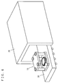
- the MRI apparatus collected from a hospital for example is brought in a factory having a heating furnace 28 as shown in Fig. 6.
- the heating furnace 28 has to be as large as to accommodate the entire magnetic field generator 10 as assembled state.
- the heating furnace 28 preferably has approximate entrance size of 2 m x 2 m, with depth of about 5 m.
- the heating furnace 28 can be an electric furnace or a heavy-oil furnace, with the electric furnace being easier in temperature control.
- heating operation is performed in accordance with a heat pattern, as will be described later.
- the magnetic field generator 10 is allowed to cool naturally. Thereafter, the bolts 18a, 18b of the magnetic field generator 10 are loosened, and the neodymium magnets 22 are removed and collected.
- the plate yokes 12a, 12b may be separated from the column yokes 24 before removing the neodymium magnets 22. Outer surfaces of the collected neodymium magnets 22 are polished.
- the neodymium magnets 22 are given aging (heat) treatment in a tempering furnace (not illustrated) as necessary, at a temperature of 450°C ⁇ 600°C, for not less than three hours for example, to recover the magnetic characteristic.
- the neodymium magnets 22 are then checked for dimensions and its magnetic characteristic, and reused.
- the heating furnace 28 suitably used in this method is an electric furnace.
- the heating is performed at a temperature, at which the neodymium magnets 22 are demagnetized to an extent not deteriorated in magnetic characteristic, and at which the adhesive is not carbonized.
- the adhesive is degraded by the heat and becomes brittle but not to an extent that the neodymium magnets 22 can be readily removed, so the adhesive must be ground off.
- a temperature is increased to 200°C ⁇ 350°C, and more preferably to 300°C as shown by curve C in Fig. 7, and then the temperature is maintained for 5 hours.
- this operation reduces the magnetism of the neodymium magnets 22 to not higher than 0.07 T.
- the plate yokes 12a, 12b are removed from the column yokes 24, and then, the pole pieces 16a, 16b are removed from the plate yokes 12a, 12b respectively, the adhesive is ground off and the neodymium magnets 22 are taken off.
- the adhesive can be machine-ground by a surface grinder for example.
- the neodymium magnets 22 can be taken out safely only by physically removing the degraded adhesive, and the magnetic field generator 10 can be dismantled safely. Further, since the surfaces of the neodymium magnets 22 are not deteriorated, the neodymium magnets 22 can be reused easily by only cleaning the surfaces of the neodymium magnets 22 and then re-magnetizing the neodymium magnets 22.
- the heating is made at a temperature not higher than 400°C, there is no need for performing the aging (heat) treatment to the neodymium magnets 22 after the heating operation.
- heating furnace 28 can be used for heating the magnetic field generator 10, cost of dismantling can be lower than in the related art.
- the adhesive may be solved in a drum filled with the solvent.
- the solvent available for this operation may be ethyl acetate, methyl ethyl ketone, acetone and so on, but because of low penetrability of these solvents, the neodymium magnets 22 must be soaked for about a week, On the other hand, if a solvent having a high penetrability such as methylene chloride, ethylene chloride and so on is used, the neodymium magnets 22 can be removed in about 24 hours, but a large-scale facility such as a ventilation system is necessary in order to deal with intense vaporization of the solvent.
- the heating furnace 28 suitably used in this method is a heavy-oil furnace.
- the heavy-oil furnace requires lower cost for the heating.
- the magnetic field generator 10 is heated to a temperature above the Curie temperature (340°C), and the adhesive is carbonized, for making possible to dismantle the magnetic field generator 10.
- the entire magnetic field generator 10 is placed in the heating furnace 28, and the temperature is increased to 550°C spending four hours as shown by curve D in fig. 7. Thereafter, the temperature is maintained for 5 hours, the natural cooling is performed and then the magnetic field generator 10 is taken out of the furnace. After the natural cooling, the plate yokes 12a, 12b are removed from the column yokes 24, and then, the pole pieces 16a, 16b are removed from the plate yokes 12a, 12b respectively, and the neodymium magnets 22 are removed. Carbon sticks on surfaces of the removed neodymium magnets 22.
- the surfaces of the neodymium magnets 22 are carbonized and oxidized, so the neodymium magnets 22 as removed are not easily re-bonded. Therefore, the surfaces of the removed neodymium magnets 22 are polished by a depth of about 0.1 mm ⁇ 0.5 mm for removal of the carbonized and oxidized portions. After the polishing, re-aging is performed at a temperature of 500°C for an hour so as to allow the neodymium magnets 22 to re-attain the magnetic characteristic.
- the heating temperature must not be higher than 1000°C, because too high a temperature in the heating furnace 28 promotes grain growth of a tetragonal crystals of Nd2Fe14B, deteriorating the coercive force of the neodymium magnets 22.
- adhesive is carbonated to lose adhering strength, and the neodymium magnets 22 lose the magnetism almost completely, and therefore the removal and handling of the neodymium magnets 22 are easily, and the magnetic field generator 10 can be dismantled safely.
- the adhesion necessary for re-bonding the neodymium magnets 22 can be recovered. Further, by re-aging the neodymium magnets 22, the characteristic of the neodymium magnets 22 can be reliably reestablished.
- the as-magnetized neodymium magnets 22 are very dangerous. However, by heating the column yokes 24 at least as connected to the plate yoke 12a or 12b, or as integrated in the magnetic field generator 10 as shown in Fig. 1, in the heating furnace 28, the dismantling operation can be performed more safely. Needless to say, in the dismantling, the plate yoke as connected with the permanent magnet may be heated in the heating furnace 28 in a state disconnected from the column yokes 24.
Landscapes
- Engineering & Computer Science (AREA)
- Physics & Mathematics (AREA)
- Power Engineering (AREA)
- Environmental & Geological Engineering (AREA)
- Electromagnetism (AREA)
- Thermal Sciences (AREA)
- Condensed Matter Physics & Semiconductors (AREA)
- General Physics & Mathematics (AREA)
- Magnetic Resonance Imaging Apparatus (AREA)
Applications Claiming Priority (2)
| Application Number | Priority Date | Filing Date | Title |
|---|---|---|---|
| JP20129199 | 1999-07-15 | ||
| JP20129199 | 1999-07-15 |
Publications (2)
| Publication Number | Publication Date |
|---|---|
| EP1069575A1 true EP1069575A1 (fr) | 2001-01-17 |
| EP1069575B1 EP1069575B1 (fr) | 2008-05-14 |
Family
ID=16438555
Family Applications (1)
| Application Number | Title | Priority Date | Filing Date |
|---|---|---|---|
| EP00114873A Expired - Lifetime EP1069575B1 (fr) | 1999-07-15 | 2000-07-11 | Procédé de démontage pour générateur de champ magnétique |
Country Status (4)
| Country | Link |
|---|---|
| US (3) | US6634089B1 (fr) |
| EP (1) | EP1069575B1 (fr) |
| CN (1) | CN1209773C (fr) |
| DE (1) | DE60038849D1 (fr) |
Cited By (3)
| Publication number | Priority date | Publication date | Assignee | Title |
|---|---|---|---|---|
| US6634089B1 (en) * | 1999-07-15 | 2003-10-21 | Sumitomo Special Metals Co. Ltd. | Method for dismantling a magnetic field generator |
| EP3255645A1 (fr) * | 2016-06-08 | 2017-12-13 | Audi Ag | Procédé de recyclage d'au moins un aimant d'une machine électrique |
| WO2021119063A1 (fr) * | 2019-12-10 | 2021-06-17 | Hyperfine Research, Inc. | Cadre ferromagnétique pour imagerie par résonance magnétique |
Families Citing this family (13)
| Publication number | Priority date | Publication date | Assignee | Title |
|---|---|---|---|---|
| US6518867B2 (en) * | 2001-04-03 | 2003-02-11 | General Electric Company | Permanent magnet assembly and method of making thereof |
| JP2003130937A (ja) * | 2001-10-24 | 2003-05-08 | Hitachi Ltd | 溶液用核磁気共鳴分析装置 |
| WO2003068066A1 (fr) * | 2002-02-15 | 2003-08-21 | Sumitomo Special Metals Co., Ltd. | Generateur de champ magnetique et son procede de fabrication |
| WO2006038261A1 (fr) * | 2004-09-30 | 2006-04-13 | Neomax Co., Ltd. | Generateur de champ magnétique pour mri |
| US20070285197A1 (en) * | 2006-06-08 | 2007-12-13 | General Electric Company | Method for disassembling a magnetic field generator |
| US20110175694A1 (en) * | 2008-06-24 | 2011-07-21 | Fallone B Gino | Magnetic assembly and method for defining a magnetic field for an imaging volume |
| EP2333935B1 (fr) * | 2008-10-02 | 2016-01-06 | Nissan Motor Co., Ltd. | Aimant a pole de champ, procede de fabrication d' aimant a pole de champ et machine rotative a aimant permanent |
| JP5056959B2 (ja) * | 2011-01-13 | 2012-10-24 | 三菱マテリアル株式会社 | モータのリサイクル方法 |
| KR101607409B1 (ko) * | 2011-07-27 | 2016-03-29 | 닛산 지도우샤 가부시키가이샤 | 계자극용 자석체의 제조 장치 및 그 제조 방법 |
| CN111983537B (zh) * | 2020-08-19 | 2023-06-06 | 深圳航天科技创新研究院 | 一种导磁与承重功能分离的磁共振磁体结构 |
| CN112454247A (zh) * | 2020-11-24 | 2021-03-09 | 华北水利水电大学 | 一种实验用强磁性物体分离装置及方法 |
| EP4019995B1 (fr) * | 2020-12-22 | 2023-08-16 | Bruker BioSpin GmbH | Spectromètre rpe doté d'au moins une pièce polaire composé au moins partiellement d'un matériau fonctionnel |
| CN118737619B (zh) * | 2024-07-12 | 2025-09-30 | 江西汉驱智能科技有限公司 | 一种半自动往复式去磁铁装置 |
Citations (3)
| Publication number | Priority date | Publication date | Assignee | Title |
|---|---|---|---|---|
| JPS61140106A (ja) * | 1984-12-13 | 1986-06-27 | Sumitomo Special Metals Co Ltd | 永久磁石の着磁組立方法 |
| US4900374A (en) * | 1989-08-24 | 1990-02-13 | General Motors Corporation | Demagnetization of iron-neodymium-boron type permanent magnets without loss of coercivity |
| US5659250A (en) * | 1996-03-19 | 1997-08-19 | Intermagnetics General Corporation | Full brick construction of magnet assembly having a central bore |
Family Cites Families (10)
| Publication number | Priority date | Publication date | Assignee | Title |
|---|---|---|---|---|
| US634088A (en) * | 1898-09-13 | 1899-10-03 | Julian Kennedy | Adjusting mechanism. |
| US4679022A (en) * | 1985-12-27 | 1987-07-07 | Sumitomo Special Metal Co. Ltd. | Magnetic field generating device for NMR-CT |
| US4943774A (en) * | 1989-06-01 | 1990-07-24 | General Atomics | Magnetic field control apparatus |
| JPH0320045A (ja) | 1989-06-16 | 1991-01-29 | Matsushita Electron Corp | 半導体装置およびその製造方法 |
| JPH0831635A (ja) * | 1994-07-08 | 1996-02-02 | Sumitomo Special Metals Co Ltd | Mri用磁界発生装置 |
| JP2000139874A (ja) * | 1998-09-02 | 2000-05-23 | Sumitomo Special Metals Co Ltd | Mri用磁界発生装置 |
| KR100319923B1 (ko) * | 1999-05-10 | 2002-01-09 | 윤종용 | 자기공명영상장치용 자기장 발생 장치 |
| EP1069575B1 (fr) * | 1999-07-15 | 2008-05-14 | Neomax Co., Ltd. | Procédé de démontage pour générateur de champ magnétique |
| JP3180331B2 (ja) * | 1999-07-15 | 2001-06-25 | 住友特殊金属株式会社 | 磁界発生装置の解体方法および磁界発生装置のリサイクル方法 |
| JP3788573B2 (ja) * | 2000-11-16 | 2006-06-21 | 信越化学工業株式会社 | Mri用磁気回路の組立方法 |
-
2000
- 2000-07-11 EP EP00114873A patent/EP1069575B1/fr not_active Expired - Lifetime
- 2000-07-11 DE DE60038849T patent/DE60038849D1/de not_active Expired - Lifetime
- 2000-07-13 US US09/615,729 patent/US6634089B1/en not_active Expired - Lifetime
- 2000-07-14 CN CN00121906.5A patent/CN1209773C/zh not_active Expired - Lifetime
-
2003
- 2003-08-26 US US10/647,238 patent/US7051425B2/en not_active Expired - Lifetime
-
2006
- 2006-03-31 US US11/393,652 patent/US7143507B2/en not_active Expired - Lifetime
Patent Citations (3)
| Publication number | Priority date | Publication date | Assignee | Title |
|---|---|---|---|---|
| JPS61140106A (ja) * | 1984-12-13 | 1986-06-27 | Sumitomo Special Metals Co Ltd | 永久磁石の着磁組立方法 |
| US4900374A (en) * | 1989-08-24 | 1990-02-13 | General Motors Corporation | Demagnetization of iron-neodymium-boron type permanent magnets without loss of coercivity |
| US5659250A (en) * | 1996-03-19 | 1997-08-19 | Intermagnetics General Corporation | Full brick construction of magnet assembly having a central bore |
Non-Patent Citations (1)
| Title |
|---|
| PATENT ABSTRACTS OF JAPAN vol. 010, no. 337 (E - 454) 14 November 1986 (1986-11-14) * |
Cited By (10)
| Publication number | Priority date | Publication date | Assignee | Title |
|---|---|---|---|---|
| US6634089B1 (en) * | 1999-07-15 | 2003-10-21 | Sumitomo Special Metals Co. Ltd. | Method for dismantling a magnetic field generator |
| US7051425B2 (en) | 1999-07-15 | 2006-05-30 | Neomax Co., Ltd. | Recycling method for magnetic field generator |
| US7143507B2 (en) | 1999-07-15 | 2006-12-05 | Neomax Co., Ltd. | Recycling method for magnetic field generator |
| EP3255645A1 (fr) * | 2016-06-08 | 2017-12-13 | Audi Ag | Procédé de recyclage d'au moins un aimant d'une machine électrique |
| WO2021119063A1 (fr) * | 2019-12-10 | 2021-06-17 | Hyperfine Research, Inc. | Cadre ferromagnétique pour imagerie par résonance magnétique |
| US11333727B2 (en) | 2019-12-10 | 2022-05-17 | Hyperfine Operations, Inc. | Ferromagnetic frame for magnetic resonance imaging |
| US11422213B2 (en) | 2019-12-10 | 2022-08-23 | Hyperfine Operations, Inc. | Ferromagnetic frame for magnetic resonance imaging |
| CN115552270A (zh) * | 2019-12-10 | 2022-12-30 | 海珀菲纳运营有限公司 | 用于磁共振成像的铁磁框架 |
| US11971465B2 (en) | 2019-12-10 | 2024-04-30 | Hyperfine Operations, Inc. | Ferromagnetic frame for magnetic resonance imaging |
| US12553968B2 (en) | 2019-12-10 | 2026-02-17 | Hyperfine Operations, Inc. | Ferromagnetic frame for magnetic resonance imaging |
Also Published As
| Publication number | Publication date |
|---|---|
| EP1069575B1 (fr) | 2008-05-14 |
| CN1209773C (zh) | 2005-07-06 |
| US6634089B1 (en) | 2003-10-21 |
| US7051425B2 (en) | 2006-05-30 |
| US7143507B2 (en) | 2006-12-05 |
| US20040041566A1 (en) | 2004-03-04 |
| CN1280811A (zh) | 2001-01-24 |
| DE60038849D1 (de) | 2008-06-26 |
| US20060168799A1 (en) | 2006-08-03 |
Similar Documents
| Publication | Publication Date | Title |
|---|---|---|
| US7143507B2 (en) | Recycling method for magnetic field generator | |
| CA1216623A (fr) | Aimants de terre rare frittee | |
| KR100381813B1 (ko) | Mri용 자계 발생 장치와 조립 방법 및, 자계 발생 장치용 자석 유닛의 조립 방법 | |
| US4902361A (en) | Bonded rare earth-iron magnets | |
| US4829277A (en) | Isotropic rare earth-iron field magnets for magnetic resonance imaging | |
| US6602352B2 (en) | Method for manufacturing rare earth magnet and powder compacting apparatus | |
| WO1989011752A1 (fr) | Procede de construction d'un rotor a aimant permanent | |
| US7847555B2 (en) | MRI apparatus with high-resistance magnet | |
| JP4012311B2 (ja) | バルク超電導部材とマグネットおよびそれらの製造方法 | |
| JPH09163649A (ja) | 永久磁石埋め込み形モータにおける永久磁石の固定方法 | |
| US4911882A (en) | Process for producing permanent magnets | |
| JP3180331B2 (ja) | 磁界発生装置の解体方法および磁界発生装置のリサイクル方法 | |
| US6781495B2 (en) | Magnetic field generator and assembling method thereof | |
| JP4190025B2 (ja) | Mri用磁気回路の組立方法 | |
| CN218241474U (zh) | 一种钕铁硼磁体多极分段充磁装置 | |
| KR102777865B1 (ko) | RE-Fe-B계 경희토류 불화물 입계확산 자석 및 이의 제조방법 | |
| JP2004128302A (ja) | 希土類焼結磁石 | |
| JPH05199686A (ja) | モータの磁石積層型回転子 | |
| JPH0614519A (ja) | 磁気回路の分解方法 | |
| Akiyama et al. | Fabrication of rare-earth patterned laser ceramics by use of gradient magnetic field | |
| Hirosawa et al. | Microstructure of Nd/Nd sub 2 Fe sub 14 B Interface and Coercivity of Surface Grains in Neodymium-Coated Nd sub 15 Fe sub 77 B sub 8 Sintered Magnet | |
| Takabayashi | Design of A Magnetic Circuit for An Undulator by Using the Integral Equation Method | |
| JPH06260356A (ja) | 移送一体成形磁気回路の製造方法 |
Legal Events
| Date | Code | Title | Description |
|---|---|---|---|
| PUAI | Public reference made under article 153(3) epc to a published international application that has entered the european phase |
Free format text: ORIGINAL CODE: 0009012 |
|
| AK | Designated contracting states |
Kind code of ref document: A1 Designated state(s): DE GB IT |
|
| AX | Request for extension of the european patent |
Free format text: AL;LT;LV;MK;RO;SI |
|
| 17P | Request for examination filed |
Effective date: 20010712 |
|
| AKX | Designation fees paid |
Free format text: DE GB IT |
|
| RAP1 | Party data changed (applicant data changed or rights of an application transferred) |
Owner name: NEOMAX CO., LTD. |
|
| 17Q | First examination report despatched |
Effective date: 20070105 |
|
| GRAP | Despatch of communication of intention to grant a patent |
Free format text: ORIGINAL CODE: EPIDOSNIGR1 |
|
| RTI1 | Title (correction) |
Free format text: DISMANTLING METHOD FOR MAGNETIC FIELD GENERATOR |
|
| RIN1 | Information on inventor provided before grant (corrected) |
Inventor name: AOKI, MASAAKI Inventor name: HASHIMOTO, SHIGEO |
|
| GRAS | Grant fee paid |
Free format text: ORIGINAL CODE: EPIDOSNIGR3 |
|
| GRAA | (expected) grant |
Free format text: ORIGINAL CODE: 0009210 |
|
| AK | Designated contracting states |
Kind code of ref document: B1 Designated state(s): DE GB IT |
|
| REG | Reference to a national code |
Ref country code: GB Ref legal event code: FG4D |
|
| REF | Corresponds to: |
Ref document number: 60038849 Country of ref document: DE Date of ref document: 20080626 Kind code of ref document: P |
|
| RAP2 | Party data changed (patent owner data changed or rights of a patent transferred) |
Owner name: HITACHI METALS, LTD. |
|
| PLBE | No opposition filed within time limit |
Free format text: ORIGINAL CODE: 0009261 |
|
| STAA | Information on the status of an ep patent application or granted ep patent |
Free format text: STATUS: NO OPPOSITION FILED WITHIN TIME LIMIT |
|
| 26N | No opposition filed |
Effective date: 20090217 |
|
| GBPC | Gb: european patent ceased through non-payment of renewal fee |
Effective date: 20080814 |
|
| PG25 | Lapsed in a contracting state [announced via postgrant information from national office to epo] |
Ref country code: GB Free format text: LAPSE BECAUSE OF NON-PAYMENT OF DUE FEES Effective date: 20080814 |
|
| PGFP | Annual fee paid to national office [announced via postgrant information from national office to epo] |
Ref country code: DE Payment date: 20190625 Year of fee payment: 20 Ref country code: IT Payment date: 20190719 Year of fee payment: 20 |
|
| REG | Reference to a national code |
Ref country code: DE Ref legal event code: R071 Ref document number: 60038849 Country of ref document: DE |