EP1069533B1 - Efficient methods and apparatus for resampling three-dimensional datasets - Google Patents
Efficient methods and apparatus for resampling three-dimensional datasets Download PDFInfo
- Publication number
- EP1069533B1 EP1069533B1 EP00305983A EP00305983A EP1069533B1 EP 1069533 B1 EP1069533 B1 EP 1069533B1 EP 00305983 A EP00305983 A EP 00305983A EP 00305983 A EP00305983 A EP 00305983A EP 1069533 B1 EP1069533 B1 EP 1069533B1
- Authority
- EP
- European Patent Office
- Prior art keywords
- line segments
- data
- sampling
- volume
- parallel line
- Prior art date
- Legal status (The legal status is an assumption and is not a legal conclusion. Google has not performed a legal analysis and makes no representation as to the accuracy of the status listed.)
- Expired - Lifetime
Links
Images
Classifications
-
- G—PHYSICS
- G06—COMPUTING; CALCULATING OR COUNTING
- G06T—IMAGE DATA PROCESSING OR GENERATION, IN GENERAL
- G06T19/00—Manipulating 3D models or images for computer graphics
-
- G—PHYSICS
- G06—COMPUTING; CALCULATING OR COUNTING
- G06T—IMAGE DATA PROCESSING OR GENERATION, IN GENERAL
- G06T15/00—3D [Three Dimensional] image rendering
- G06T15/08—Volume rendering
-
- Y—GENERAL TAGGING OF NEW TECHNOLOGICAL DEVELOPMENTS; GENERAL TAGGING OF CROSS-SECTIONAL TECHNOLOGIES SPANNING OVER SEVERAL SECTIONS OF THE IPC; TECHNICAL SUBJECTS COVERED BY FORMER USPC CROSS-REFERENCE ART COLLECTIONS [XRACs] AND DIGESTS
- Y10—TECHNICAL SUBJECTS COVERED BY FORMER USPC
- Y10S—TECHNICAL SUBJECTS COVERED BY FORMER USPC CROSS-REFERENCE ART COLLECTIONS [XRACs] AND DIGESTS
- Y10S378/00—X-ray or gamma ray systems or devices
- Y10S378/901—Computer tomography program or processor
Definitions
- This invention relates generally to methods and apparatus for re-sampling of data and more particularly to methods and apparatus for re-sampling three dimensional datasets for visual processing and display of medical data.
- an x-ray source projects a fan-shaped beam which is collimated to lie within an X-Y plane of a Cartesian coordinate system and generally referred to as the "imaging plane".
- the x-ray beam passes through the object being imaged, such as a patient.
- the beam after being attenuated by the object, impinges upon an array of radiation detectors.
- the intensity of the attenuated beam radiation received at the detector array is dependent upon the attenuation of the x-ray beam by the object.
- Each detector element of the array produces a separate electrical signal that is a measurement of the beam attenuation at the detector location.
- the attenuation measurements from all the detectors are acquired separately to produce a transmission profile.
- the x-ray source and the detector array are rotated with a gantry within the imaging plane and around the object to be imaged so that the angle at which the x-ray beam intersects the object constantly changes.
- a group of x-ray attenuation measurements, i.e., projection data, from the detector array at one gantry angle is referred to as a "view”.
- a "scan" of the object comprises a set of views made at different gantry angles, or view angles, during one revolution of the x-ray source and detector.
- the projection data is processed to construct an image that corresponds to a two dimensional slice taken through the object.
- CT numbers integers
- Hounsfield units integers used to control the brightness of a corresponding pixel on a cathode ray tube display.
- One popular visualization technique for medical applications is to resample a volume of medical data acquired from a CT or MRI imaging system along a plane of arbitrary slope. This visualization technique is known as a reformat. Volume re-sampling along a plane is commonly called a reformat of a given volume. Reformatting allows viewing of cross-sections of pathology and provides the ability to take accurate measurements of structures, aneurysms, areas, and distances, among other things.
- Interactive placement would provide for the display of a first reformat plane image followed by the production and display of a new reformat plane image, where the new reformat plane is incrementally different in scale, rotation, or translation from the first reformat plane.
- Interactive placement demands good re-sampling performance of the data, usually requiring about 10 reformat images per second to be generated. Without adequate performance, interactive placement is difficult to control. Systems known to date have not been capable of providing adequate re-sampling performance
- US 5,722,408 discloses a method for image generation in an imaging system of medical technology.
- a method of curved planar reformatted CT angiography is disclosed by Ochi, T. et al., 'Curved planar reformatted CT angiography: usefulness for the revaluation of anerysms at the carotid siphon', AJNR Am J Neuroradiol. 20: 1025 to 1030, June/July 1999 .
- GB 2 325 835 discloses a volumetric pre-clipping method in a volumetric rendering system.
- a method for rapidly re-sampling a three-dimensional volume of data to permit efficient interactive viewing and visualization of the data comprising selecting a set of parallel line segments defining a surface having a constant slope in at least one direction and intersecting the three-dimensional volume, wherein selecting a set of parallel line segments comprises the step of clipping ends of the line segments so that the clipped line segments lie wholly within the three-dimensional volume ; and processing the data by re-sampling the three-dimensional volume of data at points on the parallel line segments to generate a reformatted image of the data, in which, the processing comprises selecting a specialized sampling function corresponding to a slope of the parallel line segments and comprising a trilinear interpolation, nearest neighbor or process sampling function; processing the data at points on the clipped line segments; and computing the selected sampling of the data at points along the clipped line segments.
- Selecting a specialized sampling function corresponding to a slope of the parallel line segments may comprise the step of selecting one of a plurality of specialized sampling functions in accordance with a slope of the parallel line segments.
- Selecting one of a plurality of specialized sampling functions may comprise the step of selecting a specialized sampling function having a selected interpolation method from among several specialized sampling functions corresponding to a slope of the parallel line segments and that provide different interpolation methods.
- a system for rapidly re-sampling a three-dimensional volume of data for efficient interactive viewing and visualization of the data said system configured to select a set of parallel line segments defining a surface having a constant slope in at least one direction and intersecting the three-dimensional volume; clip ends of the parallel line segments so that the clipped line segments lie wholly within the three-dimensional volume; process the data by re-sampling the three-dimensional volume of data at points on the parallel line segments to generate a reformatted image of the data; in which said system is further configured to select a specialized sampling function corresponding to a slope of the parallel line segments and comprising a trilinear interpolation, nearest neighbor or process sampling function; process the data at points on the clipped line segments; and compute the selected sampling of the data at points along the clipped line segments.
- the system may be further configured to select a set of parallel line segments in a surface having a pair of orthogonal axes, the surface having curvature along exactly one of the pair of orthogonal axes.
- the system may be further configured to determine a first set of faces of the volume for clipping a first endpoint of each of the line segments and a second set of faces of the volume for clipping a second, opposite endpoint of the line segments, to analyze, for each line segment, the first endpoint of the line segment and the first set of faces to clip at a first clipping point, and to analyze the second endpoint of the line segment and the second set of faces to clip at a second clipping point.
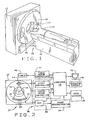
- a computed tomograph (CT) imaging system 10 is shown as including a gantry 12 representative of a "third generation" CT scanner.
- Gantry 12 has an x-ray source 14 that projects a beam of x-rays 16 toward a detector array 18 on the opposite side of gantry 12.
- Detector array 18 is formed by detector elements 20 which together sense the projected x-rays that pass through a medical patient 22.
- Detector array 18 may be fabricated in a single slice or multislice configuration.
- Each detector element 20 produces an electrical signal that represents the intensity of an impinging x-ray beam and hence the attenuation of the beam as it passes through patient 22.
- gantry 12 and the components mounted thereon rotate about a center of rotation 24.
- Control mechanism 26 includes an x-ray controller 28 that provides power and timing signals to x-ray source 14 and a gantry motor controller 30 that controls the rotational speed and position of gantry 12.
- a data acquisition system (DAS) 32 in control mechanism 26 samples analog data from detector elements 20 and converts the data to digital signals for subsequent processing.
- An image reconstructor 34 receives sampled and digitized x-ray data from DAS 32 and performs high speed image reconstruction. The reconstructed image is applied as an input to a computer 36 which stores the image in a mass storage device 38.
- DAS data acquisition system
- Computer 36 also receives commands and scanning parameters from an operator via console 40 that has a keyboard.
- An associated cathode ray tube display 42 allows the operator to observe the reconstructed image and other data from computer 36.
- the operator supplied commands and parameters are used by computer 36 to provide control signals and information to DAS 32, x-ray controller 28 and gantry motor controller 30.
- computer 36 operates a table motor controller 44 which controls a motorized table 46 to position patient 22 in gantry 12. Particularly, table 46 moves portions of patient 22 through gantry opening 48.
- a scan of patient 22 results in the collection of a volume of medical data.
- Interactive volume re-sampling of this data allows viewing cross-sections of pathology to take accurate measurements of strictures, aneurysms, areas, and distances.
- the invention provides a fast and efficient clipping method that is applicable to re-sampling surfaces that can be modeled as a set of line segments of identical slope. These surfaces include planes and other surfaces having two orthogonal axes and curvature along one of the axes, but not the other.
- One example of such a surface is a Z-plane, with a displacement along the x axis, or along the y axis.
- These types of surfaces can have key clipping aspects determined for all line segments on the surface, accelerating the clipping process for each line segment.
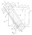
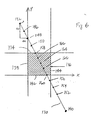
- a re-sampling plane 50 with a data volume 52, represented, for example, by a cube, is illustrated in Figure 3 .
- Dashed lines e.g., 54
- re-sampling at points in data volume 52 begins by clipping each of the line segments in plane 50 until sampling points are interior to the volume 52, or a line segment being analyzed is found to be entirely outside volume 52.
- Line segments 56, 58, 60, 62, 64, 66, and 68 lying within plane 50 are representative of the types of line segments to be analyzed for clipping. Some of these line segments (56, 58, 66, 68) lie entirely outside the volume.
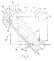
- a curved re-sampling surface is examined.
- figure 4 represents the intersection of a curved re-sampling surface 72 with data volume 52.
- Re-sampling surface 72 is curved, but is still characterized or defined by parallel line segments 74, 76, 78, 80, 82, 84, and 86 having equal slope. The slope of these parallel line segments defines an axis A of re-sampling surface 72.
- the re-sampling surface is a curved sheet 88 lying entirely within volume 52.
- Segment ends are clipped back until re-sampling points are interior to volume 52 or the segment is found to be entirely outside the volume.
- the process is performed in two iterates, one for each end of the line segment. The process starts with one extreme sample point along the line segment and tests each sample point until either the other extreme end of the line segment is encountered or a sample point interior to the volume is found. Because the segment endpoints are clipped in the beginning, step-and-interpolate iterations that process the sample points within the data volume can be performed free of bounds checking. In other words, it is not necessary to check each point within the step-and-interpolate iterations to determine whether the point being processed is inside or outside the data volume. The efficiency of the reformatting operation is increased because this check is eliminated from the iterations.
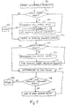
- Figure 5 is a flow chart of a clipping procedure that is used in one embodiment. Execution of the procedure starts at block 90, where one of the two opposite endpoints of a line segment of the sampling plane is selected. At block 92, a test is performed to determine whether the selected point is within a boundary of data volume 52 represented by the lower faces of the volume. This boundary corresponds, for example, to bottom face 94, right face 96, and front face 98 of volume 52 in Figures 3 and 4 , but different faces appropriate for this test are used, depending upon an orientation of a sampling surface, for example, 50 or 72. If the point is not within the lower faces, i.e., within the data volume, execution proceeds to block 100. Otherwise, execution continues at block 102.
- Block 100 is executed only if the re-sampling point under consideration is outside data volume 52.
- the output point i.e., the visual representation point or pixel corresponding to the re-sampling point
- the output point is filled with "background" data to indicate that the output point is outside data volume 52 and thus, no medical data is available.
- Execution then proceeds to block 104, in which a test is performed to determine whether the opposite end of the line segment has been reached. If so, it is not necessary to check the line segment any further, because the line segment lies entirely outside of data volume 52. Execution thus returns to the calling procedure at block 106, which either checks another line segment of the re-sampling surface or proceeds to other processing. Otherwise, a step is taken along the current line segment towards the opposite endpoint at block 108, thereby selecting a new re-sampling point as a possible clipping endpoint. Execution then loops back to block 92.
- the point being checked is between the lower and upper faces of data volume 52, it is a point at which interpolation is performed 122.
- the interpolation function is efficiently performed at block 122, because no checking need be done in the interpolation function to determine whether the point is within data volume 52.
- a check is performed at block 124 to determine whether this point is the last point on the segment. If so, execution returns 126 to the calling function. Otherwise, the next sample point on the line segment is selected at block 128, and execution loops back to block 122 until the last point is selected.
- a feature of this clipping procedure is that, when all the line segments on a surface have the same slope, as is the case with those aligned with the A axes in Figures 3 and 4 , it can easily be determined which three faces of volume 52 are required for checking each segment endpoint.
- a procedure for clipping segment 130 from its upper endpoint 132 need only take into account the upper Y coordinate face 134 of region 136 and the lower X coordinate face 138 of region 136.
- a procedure need only take into account lower Y coordinate face 142 and upper X coordinate face 144. This analysis need only be performed once for a surface.
- points at which background filling occur are represented at 132, 146, 148, 150, 140, 152, 154, and 156.
- Line segment 130 is clipped at points 158 and 160; points 162, 164, and 166 are representative of points within data volume 136.
- points 162, 164, and 166 are representative of points within data volume 136.
- line segments 56 and 74 lie entirely outside their respective volumes 52.
- Line segments 60 and 78 are clipped. Background filling of output points between points 168 and 170 and between points 172 and 174 of line segment 60 in Figure 3 and between points 176 and 178 and between points 180 and 182 of line segment 78 in Figure 4 occurs.
- a specialized sampler is employed.
- a specialized sampler selected in accordance with a slope of the line segments on the re-sampling surface is employed for all line segments on the surface.
- a specialized sampler selected in accordance with the slope of axis A is employed for that portion of line segment 60 on sheet 70, i.e., that portion of line segment 60 that is between the clipping points 170 and 174.
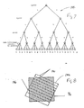
- a decision tree is used to select a specialized sampler.
- An example of such a decision tree 184 is represented in Figure 7 .
- Decision tree 184 is used to select a specialized sampler according to a sign of a slope of line segments in a direction of each of the x, y, and z axes.
- a specialized sampler optimized for each combination of possible line segment slopes is provided.
- specialized samplers are provided for different interpolation methods and different sample point processing demands.
- trilinear interpolation and nearest neighbor interpolation are used, such interpolation methods being known in the art.
- the invention is not limited to only these interpolation methods.
- other interpolation methods such as high-order interpolation along one axis of the volume, and lower order interpolation along the remaining axes of the volume are provided.
- Common choices of processing demands include inline save in interpolated values, or function invocation for each sample point for further processing.
- the second processing demand is used for planar re-sampling.
- Figure 8 is a two-dimensional representation of an embodiment of planar re-sampling. Extensions of this representation to three dimensions will be evident to those skilled in the art.
- a baseline segment 186 forms one edge of the sampling region 188. From baseline segment 186, sampling line segments 190 normal to this edge provide scanline segments. These scanline segments will generate the interpolated sample values used in an output image.
- the sampler functions are generated using class-structured sets of macros and a control logic macro.
- Class-structured sets of macros are those sets of macros having inheritance, encapsulation, and virtual methods.
- the class-structured set of macros define a stepper point class which implements the interpolation or processing method. This class includes the following methods:
- the stepper controller macro builds up the overall function by referencing the macro-implemented methods of the stepper point class.
- all the specialized sampler functions are generated.
- the following code segment is used in one embodiment to generate the sampler functions using C/C + + program code (the line numbers preceding each statement are not part of the code but are provided only for reference purposes).
- equivalent code is written to take advantage of corresponding features in another computer language.
- the first line includes the set of macro definitions defining the methods for the trilinear interpolation style point stepper,
- the VtkM4Stepper macro is the stepper controller macro. This macro uses its arguments to generate the line-segment slope-specific clipping code and to create a unique function name.
- Line 11 redefines the stepper methods with the nearest neighbor interpolation style point stepper.
- Line 21 again replaces the stepper methods with the process-point style point stepper used to implement the baseline segment stepper.
- the point stepper's Const() support good run-time performance and encapsulation by generating local variable names that are derived from the object instance name and the member variable name. Thus, data hiding is achieved within any given interpolation method.
- Standard or custom computer systems are suitable devices for performing the various method embodiments, and constitute inventive apparatus embodiments when configured to perform the inventive method embodiments.
- Such computer systems can include memory for stored programs and data, one or more standard input devices such as an operator console, mouse, or joystick, and a video display.
- a suitable computer system is provided as part of the CT imaging system in Figure 2 .
- This computer system provides mass storage 38, where medical data and a stored program to perform the method may be stored, a computer or processor 36, an operator console 40, and a display 42.
- Other apparatus embodiments are separate from an imaging system, and image data to be processed by such embodiments is transferred to the memory of the computer in any suitable manner.
- the above described methods and apparatus provide rapid and efficient re-sampling of a three-dimensional data volume to permit interactive viewing and visualization of data.
- the advantages of the inventive methods and apparatus are achieved through selection of a surface modeled as a set of line segments having identical slope, efficient clipping of the line segments, and the use and efficient management of highly optimized and specialized functions for re-sampling.
- CT system described herein is a "third generation” system in which both the x-ray source and detector rotate with the gantry.
- CT systems including "fourth generation” systems wherein the detector is a full-ring stationary detector and only the x-ray source rotates with the gantry, may be used if individual detector elements are corrected to provide substantially uniform responses to a given x-ray beam.
- the system described herein performs an axial scan, however, the invention may be used with a helical scan.
Landscapes
- Engineering & Computer Science (AREA)
- Computer Graphics (AREA)
- Physics & Mathematics (AREA)
- General Physics & Mathematics (AREA)
- Theoretical Computer Science (AREA)
- Computer Hardware Design (AREA)
- General Engineering & Computer Science (AREA)
- Software Systems (AREA)
- Apparatus For Radiation Diagnosis (AREA)
- Image Generation (AREA)
- Magnetic Resonance Imaging Apparatus (AREA)
- Processing Or Creating Images (AREA)
Applications Claiming Priority (2)
| Application Number | Priority Date | Filing Date | Title |
|---|---|---|---|
| US354822 | 1982-03-04 | ||
| US09/354,822 US6687393B1 (en) | 1999-07-16 | 1999-07-16 | Efficient methods and apparatus for resampling three dimensional datasets |
Publications (3)
| Publication Number | Publication Date |
|---|---|
| EP1069533A2 EP1069533A2 (en) | 2001-01-17 |
| EP1069533A3 EP1069533A3 (en) | 2003-07-09 |
| EP1069533B1 true EP1069533B1 (en) | 2009-10-14 |
Family
ID=23395038
Family Applications (1)
| Application Number | Title | Priority Date | Filing Date |
|---|---|---|---|
| EP00305983A Expired - Lifetime EP1069533B1 (en) | 1999-07-16 | 2000-07-14 | Efficient methods and apparatus for resampling three-dimensional datasets |
Country Status (5)
| Country | Link |
|---|---|
| US (1) | US6687393B1 (uk) |
| EP (1) | EP1069533B1 (uk) |
| JP (1) | JP4808303B2 (uk) |
| DE (1) | DE60043133D1 (uk) |
| IL (1) | IL137269A0 (uk) |
Families Citing this family (15)
| Publication number | Priority date | Publication date | Assignee | Title |
|---|---|---|---|---|
| US7006862B2 (en) * | 2001-07-17 | 2006-02-28 | Accuimage Diagnostics Corp. | Graphical user interfaces and methods for retrospectively gating a set of images |
| US7209779B2 (en) * | 2001-07-17 | 2007-04-24 | Accuimage Diagnostics Corp. | Methods and software for retrospectively gating a set of images |
| US7142703B2 (en) * | 2001-07-17 | 2006-11-28 | Cedara Software (Usa) Limited | Methods and software for self-gating a set of images |
| GB2395880B (en) | 2002-11-27 | 2005-02-02 | Voxar Ltd | Curved multi-planar reformatting of three-dimensional volume data sets |
| JP2006518074A (ja) * | 2003-02-18 | 2006-08-03 | コーニンクレッカ フィリップス エレクトロニクス エヌ ヴィ | 組織混合を使ったボリューム可視化 |
| US7777740B2 (en) * | 2003-02-20 | 2010-08-17 | Binary Simplex, Inc. | Spatial decomposition methods using bit manipulation |
| US7757162B2 (en) * | 2003-03-31 | 2010-07-13 | Ricoh Co. Ltd. | Document collection manipulation |
| US7469073B2 (en) * | 2004-05-24 | 2008-12-23 | Siemens Medical Solutions Usa, Inc. | Image-based method for detection and removal of small fragments in segmented three-dimensional volumes |
| US7826684B2 (en) * | 2005-09-21 | 2010-11-02 | Siemens Medical Solutions Usa, Inc. | Optimization and view dependency reduction for processing slice-based volumes |
| US7813591B2 (en) | 2006-01-20 | 2010-10-12 | 3M Innovative Properties Company | Visual feedback of 3D scan parameters |
| US7698014B2 (en) * | 2006-01-20 | 2010-04-13 | 3M Innovative Properties Company | Local enforcement of accuracy in fabricated models |
| CN102081697B (zh) * | 2009-11-27 | 2013-12-11 | 深圳迈瑞生物医疗电子股份有限公司 | 一种在超声成像空间中定义感兴趣容积的方法及其装置 |
| CN102184572B (zh) * | 2011-05-19 | 2017-07-21 | 威盛电子股份有限公司 | 三维图形裁剪方法、呈现方法及其图形处理装置 |
| US9091628B2 (en) | 2012-12-21 | 2015-07-28 | L-3 Communications Security And Detection Systems, Inc. | 3D mapping with two orthogonal imaging views |
| US10332252B2 (en) * | 2016-12-29 | 2019-06-25 | General Electric Company | Slope constrained cubic interpolation |
Citations (1)
| Publication number | Priority date | Publication date | Assignee | Title |
|---|---|---|---|---|
| GB2325835A (en) * | 1997-05-30 | 1998-12-02 | Hewlett Packard Co | Volumetric pre-clipping method in a volumetric rendering system |
Family Cites Families (15)
| Publication number | Priority date | Publication date | Assignee | Title |
|---|---|---|---|---|
| JPS60108977A (ja) * | 1983-11-18 | 1985-06-14 | Toshiba Corp | 画像変換装置 |
| JPH0810468B2 (ja) * | 1989-01-26 | 1996-01-31 | 株式会社東芝 | 画像表示装置 |
| JP2755267B2 (ja) * | 1989-09-28 | 1998-05-20 | 株式会社東芝 | 立体画像表示装置 |
| US5257183A (en) | 1990-12-21 | 1993-10-26 | General Electric Company | Method and apparatus for converting cone beam X-ray projection data to planar integral and reconstructing a three-dimensional computerized tomography (CT) image of an object |
| US5313567A (en) | 1991-06-13 | 1994-05-17 | At&T Bell Laboratories | Arrangement for determining and displaying volumetric data in an imaging system |
| US5734384A (en) * | 1991-11-29 | 1998-03-31 | Picker International, Inc. | Cross-referenced sectioning and reprojection of diagnostic image volumes |
| JPH08212391A (ja) * | 1995-02-03 | 1996-08-20 | Toshiba Medical Eng Co Ltd | 医療用画像変換装置 |
| JP3621146B2 (ja) * | 1995-02-16 | 2005-02-16 | 東芝医用システムエンジニアリング株式会社 | 画像診断装置 |
| DE19541500A1 (de) | 1995-11-07 | 1997-05-15 | Siemens Ag | Verfahren zur Bilderzeugung bei einem medizintechnischen bildgebenden System |
| JP2937937B2 (ja) * | 1997-04-21 | 1999-08-23 | 核燃料サイクル開発機構 | 三次元オブジェクトデータ処理方法 |
| US6084937A (en) * | 1998-07-27 | 2000-07-04 | Siemens Corporate Research, Inc. | Adaptive mask boundary correction in a cone beam imaging system |
| JP2000149047A (ja) * | 1998-11-12 | 2000-05-30 | Mitsubishi Electric Inf Technol Center America Inc | ボリュ―ムレンダリングプロセッサ |
| US6353677B1 (en) * | 1998-12-22 | 2002-03-05 | Mitsubishi Electric Research Laboratories, Inc. | Rendering objects having multiple volumes and embedded geometries using minimal depth information |
| US6254540B1 (en) * | 1999-11-19 | 2001-07-03 | Olympus Optical Co., Ltd. | Ultrasonic image processing apparatus for constructing three-dimensional image using volume-rendering data and surface-rendering data simultaneously |
| US6597756B1 (en) * | 2002-06-19 | 2003-07-22 | Ge Medical Systems Global Technology Company, Llc | Methods and apparatus for multi-slice image reconstruction |
-
1999
- 1999-07-16 US US09/354,822 patent/US6687393B1/en not_active Expired - Lifetime
-
2000
- 2000-07-12 IL IL13726900A patent/IL137269A0/xx active IP Right Grant
- 2000-07-13 JP JP2000212082A patent/JP4808303B2/ja not_active Expired - Lifetime
- 2000-07-14 EP EP00305983A patent/EP1069533B1/en not_active Expired - Lifetime
- 2000-07-14 DE DE60043133T patent/DE60043133D1/de not_active Expired - Lifetime
Patent Citations (1)
| Publication number | Priority date | Publication date | Assignee | Title |
|---|---|---|---|---|
| GB2325835A (en) * | 1997-05-30 | 1998-12-02 | Hewlett Packard Co | Volumetric pre-clipping method in a volumetric rendering system |
Also Published As
| Publication number | Publication date |
|---|---|
| JP4808303B2 (ja) | 2011-11-02 |
| IL137269A0 (en) | 2001-07-24 |
| DE60043133D1 (de) | 2009-11-26 |
| US6687393B1 (en) | 2004-02-03 |
| EP1069533A3 (en) | 2003-07-09 |
| EP1069533A2 (en) | 2001-01-17 |
| JP2001160155A (ja) | 2001-06-12 |
Similar Documents
| Publication | Publication Date | Title |
|---|---|---|
| EP1069533B1 (en) | Efficient methods and apparatus for resampling three-dimensional datasets | |
| US6415013B1 (en) | Backprojection methods and apparatus for computed tomography imaging systems | |
| EP0318176B1 (en) | Imaging methods and apparatus | |
| US5864598A (en) | Methods and apparatus for scanning an object in a computed tomography system | |
| JP2744490B2 (ja) | 物体内部構造表面の2次元像を表示する装置と方法 | |
| JP3761094B2 (ja) | 対象物の3次元画像を再構成する方法 | |
| EP0412748B1 (en) | Methods and apparatus for generating three-dimensional images | |
| JP4550426B2 (ja) | 高速発散ビーム断層撮影のための方法及び装置 | |
| US4674046A (en) | Method and apparatus for obtaining three dimensional tomographic images by interpolation of a plurality of projection slice data bind for obtaining projection data for a chosen slice | |
| US6334847B1 (en) | Enhanced image processing for a three-dimensional imaging system | |
| US8280135B2 (en) | System and method for highly attenuating material artifact reduction in x-ray computed tomography | |
| US6215841B1 (en) | Methods and apparatus for 3D artifact reduction | |
| EP0430549B1 (en) | Helical scan computed tomography | |
| Ljung et al. | Full body virtual autopsies using a state-of-the-art volume rendering pipeline | |
| US4989142A (en) | Three-dimensional images obtained from tomographic slices with gantry tilt | |
| EP0520778A1 (en) | Tomographic image reconstruction using cross-plane rays | |
| US6381297B1 (en) | High pitch reconstruction of multislice CT scans | |
| KR20040072466A (ko) | 3차원 백 프로젝션 방법 및 x-레이 ct 장치 | |
| IL116258A (en) | Image Recovery Device and Spooler Scanning Method | |
| US7602879B2 (en) | Method for increasing the resolution of a CT image during image reconstruction | |
| US7050528B2 (en) | Correction of CT images for truncated or incomplete projections | |
| US6173032B1 (en) | Methods and apparatus for image reconstruction | |
| US7215734B2 (en) | Method and system for three-dimensional reconstruction of images | |
| US20060071932A1 (en) | Method and apparatus for visualizing a sequece of volume images | |
| EP1374178A2 (en) | Fast computer tomography method |
Legal Events
| Date | Code | Title | Description |
|---|---|---|---|
| PUAI | Public reference made under article 153(3) epc to a published international application that has entered the european phase |
Free format text: ORIGINAL CODE: 0009012 |
|
| AK | Designated contracting states |
Kind code of ref document: A2 Designated state(s): AT BE CH CY DE DK ES FI FR GB GR IE IT LI LU MC NL PT SE |
|
| AX | Request for extension of the european patent |
Free format text: AL;LT;LV;MK;RO;SI |
|
| PUAL | Search report despatched |
Free format text: ORIGINAL CODE: 0009013 |
|
| AK | Designated contracting states |
Designated state(s): AT BE CH CY DE DK ES FI FR GB GR IE IT LI LU MC NL PT SE |
|
| AX | Request for extension of the european patent |
Extension state: AL LT LV MK RO SI |
|
| 17P | Request for examination filed |
Effective date: 20040109 |
|
| AKX | Designation fees paid |
Designated state(s): DE NL |
|
| 17Q | First examination report despatched |
Effective date: 20041213 |
|
| GRAP | Despatch of communication of intention to grant a patent |
Free format text: ORIGINAL CODE: EPIDOSNIGR1 |
|
| GRAS | Grant fee paid |
Free format text: ORIGINAL CODE: EPIDOSNIGR3 |
|
| GRAA | (expected) grant |
Free format text: ORIGINAL CODE: 0009210 |
|
| AK | Designated contracting states |
Kind code of ref document: B1 Designated state(s): DE NL |
|
| REF | Corresponds to: |
Ref document number: 60043133 Country of ref document: DE Date of ref document: 20091126 Kind code of ref document: P |
|
| PLBE | No opposition filed within time limit |
Free format text: ORIGINAL CODE: 0009261 |
|
| STAA | Information on the status of an ep patent application or granted ep patent |
Free format text: STATUS: NO OPPOSITION FILED WITHIN TIME LIMIT |
|
| 26N | No opposition filed |
Effective date: 20100715 |
|
| PGFP | Annual fee paid to national office [announced via postgrant information from national office to epo] |
Ref country code: NL Payment date: 20150726 Year of fee payment: 16 |
|
| PGFP | Annual fee paid to national office [announced via postgrant information from national office to epo] |
Ref country code: DE Payment date: 20150729 Year of fee payment: 16 |
|
| REG | Reference to a national code |
Ref country code: DE Ref legal event code: R119 Ref document number: 60043133 Country of ref document: DE |
|
| REG | Reference to a national code |
Ref country code: NL Ref legal event code: MM Effective date: 20160801 |
|
| PG25 | Lapsed in a contracting state [announced via postgrant information from national office to epo] |
Ref country code: DE Free format text: LAPSE BECAUSE OF NON-PAYMENT OF DUE FEES Effective date: 20170201 Ref country code: NL Free format text: LAPSE BECAUSE OF NON-PAYMENT OF DUE FEES Effective date: 20160801 |