EP1069353B1 - Drosselventil - Google Patents
Drosselventil Download PDFInfo
- Publication number
- EP1069353B1 EP1069353B1 EP00112741A EP00112741A EP1069353B1 EP 1069353 B1 EP1069353 B1 EP 1069353B1 EP 00112741 A EP00112741 A EP 00112741A EP 00112741 A EP00112741 A EP 00112741A EP 1069353 B1 EP1069353 B1 EP 1069353B1
- Authority
- EP
- European Patent Office
- Prior art keywords
- restrictor
- valve according
- feed passage
- throttle
- inlet
- Prior art date
- Legal status (The legal status is an assumption and is not a legal conclusion. Google has not performed a legal analysis and makes no representation as to the accuracy of the status listed.)
- Expired - Lifetime
Links
- 238000007789 sealing Methods 0.000 claims description 27
- 239000000463 material Substances 0.000 claims description 4
- 238000007598 dipping method Methods 0.000 claims description 2
- 238000011144 upstream manufacturing Methods 0.000 claims description 2
- 230000000903 blocking effect Effects 0.000 claims 1
- 239000012530 fluid Substances 0.000 description 7
- 230000008901 benefit Effects 0.000 description 4
- 230000008859 change Effects 0.000 description 4
- 238000004891 communication Methods 0.000 description 2
- 230000000694 effects Effects 0.000 description 2
- 230000010354 integration Effects 0.000 description 2
- 239000002184 metal Substances 0.000 description 2
- 230000000295 complement effect Effects 0.000 description 1
- 238000011161 development Methods 0.000 description 1
- 230000018109 developmental process Effects 0.000 description 1
- 238000006073 displacement reaction Methods 0.000 description 1
- 238000001746 injection moulding Methods 0.000 description 1
- 230000003993 interaction Effects 0.000 description 1
- 238000000034 method Methods 0.000 description 1
- 230000010355 oscillation Effects 0.000 description 1
- 230000008092 positive effect Effects 0.000 description 1
- 230000001105 regulatory effect Effects 0.000 description 1
- 239000006228 supernatant Substances 0.000 description 1
Images

Classifications
-
- F—MECHANICAL ENGINEERING; LIGHTING; HEATING; WEAPONS; BLASTING
- F16—ENGINEERING ELEMENTS AND UNITS; GENERAL MEASURES FOR PRODUCING AND MAINTAINING EFFECTIVE FUNCTIONING OF MACHINES OR INSTALLATIONS; THERMAL INSULATION IN GENERAL
- F16K—VALVES; TAPS; COCKS; ACTUATING-FLOATS; DEVICES FOR VENTING OR AERATING
- F16K1/00—Lift valves or globe valves, i.e. cut-off apparatus with closure members having at least a component of their opening and closing motion perpendicular to the closing faces
- F16K1/32—Details
- F16K1/52—Means for additional adjustment of the rate of flow
-
- F—MECHANICAL ENGINEERING; LIGHTING; HEATING; WEAPONS; BLASTING
- F16—ENGINEERING ELEMENTS AND UNITS; GENERAL MEASURES FOR PRODUCING AND MAINTAINING EFFECTIVE FUNCTIONING OF MACHINES OR INSTALLATIONS; THERMAL INSULATION IN GENERAL
- F16K—VALVES; TAPS; COCKS; ACTUATING-FLOATS; DEVICES FOR VENTING OR AERATING
- F16K47/00—Means in valves for absorbing fluid energy
- F16K47/08—Means in valves for absorbing fluid energy for decreasing pressure or noise level and having a throttling member separate from the closure member, e.g. screens, slots, labyrinths
-
- Y—GENERAL TAGGING OF NEW TECHNOLOGICAL DEVELOPMENTS; GENERAL TAGGING OF CROSS-SECTIONAL TECHNOLOGIES SPANNING OVER SEVERAL SECTIONS OF THE IPC; TECHNICAL SUBJECTS COVERED BY FORMER USPC CROSS-REFERENCE ART COLLECTIONS [XRACs] AND DIGESTS
- Y10—TECHNICAL SUBJECTS COVERED BY FORMER USPC
- Y10T—TECHNICAL SUBJECTS COVERED BY FORMER US CLASSIFICATION
- Y10T137/00—Fluid handling
- Y10T137/8593—Systems
- Y10T137/86493—Multi-way valve unit
- Y10T137/86718—Dividing into parallel flow paths with recombining
- Y10T137/86734—With metering feature
-
- Y—GENERAL TAGGING OF NEW TECHNOLOGICAL DEVELOPMENTS; GENERAL TAGGING OF CROSS-SECTIONAL TECHNOLOGIES SPANNING OVER SEVERAL SECTIONS OF THE IPC; TECHNICAL SUBJECTS COVERED BY FORMER USPC CROSS-REFERENCE ART COLLECTIONS [XRACs] AND DIGESTS
- Y10—TECHNICAL SUBJECTS COVERED BY FORMER USPC
- Y10T—TECHNICAL SUBJECTS COVERED BY FORMER US CLASSIFICATION
- Y10T137/00—Fluid handling
- Y10T137/8593—Systems
- Y10T137/86493—Multi-way valve unit
- Y10T137/86718—Dividing into parallel flow paths with recombining
- Y10T137/86759—Reciprocating
Definitions
- the invention relates to a throttle valve.
- a throttle valve which one adjustable in the direction of its longitudinal axis, in one fixed cage guided throttle body with annular Has recesses.
- the cage has openings, the closed at corresponding position of the throttle body or if the annular recesses in the area of Openings come, opened or partially opened are, so that from an inflow channel incoming compressed air through the openings into the interior of the valve chamber and of can flow out there via a central outflow channel. ever after axial position of the throttle body with respect to the openings in the cage so different Matterströmqueritese can be to adjust.
- throttle valves such as those in the textbook “Introduction to Pneumatic", Meixner / Kobler, page 132, have a tapered throttle body, the more depending on the throttle position or less far into an opening and thereby the assigned pressure medium different overflow cross sections provides.
- the throttle body is over Threads mounted on the valve body and can be twisted change in its axial position or throttle position.
- a big disadvantage of this conical throttle body is that non-linear adjustment behavior.
- the overflow cross section usually changes quadratically in relation to Change the axial position of the throttle body, making it very difficult to find reproducible settings.
- Another disadvantage is that between the Throttle body and the valve housing existing thread play when changing the throttle position slight oscillations the throttle cone entails. This leads to discontinuities in Studentsströmquerites and complicates the adjustment measures another.
- a throttle valve is provided, with a throttle body which can be adjusted in the direction of its longitudinal axis, depending on its position (throttle position) between an inlet and an outlet one more or less large overflow cross section releases, wherein the Throttle body having a cylindrical throttle piston, the in each throttle position coaxially into one with the inlet dipping communicating inflow channel, with its wall he in the area of a circumferential sealing zone in permanent Sealing contact is, wherein the occupied with respect to the inflow channel Axial position of the sealing zone of the current Throttle position depends, and wherein in the wall of the inflow channel on the one hand with the outlet communicating outflow channels are provided, on the other hand, along along the Verstellweges the Abdichtzone distributed overflow open into the inflow channel, wherein the overflow cross section exclusively by the front of the Abdichtzone lying, towards the inlet-side section of the inflow channel shared cross section of the overflow defined becomes.
- the relevant for the provided overflow cross section responsible component of the throttle body is now no longer tapered, but by a cylindrical Throttle piston formed, which constantly in one with immersed in the inlet communicating inflow channel.
- the between the throttle piston and the Zuströmkanalwandung existing Sealing zone prevents it from flowing over the the inflow channel supplied pressure medium at the throttle piston. Consequently, the pressure medium can only over that of the sealing zone upstream of the inlet-side section of the inflow channel Overflow openings in the Zuströmkanalwandung flow.
- the overflow cross section defined, specify variably.
- the outflow channels can be at least partially of individual be formed hole-like channels and / or a slot-like Have shape.
- the individual channels can do so be placed that their opening into the inflow channel overflow on a helix along the circumference lie the inflow channel.
- outflow channels can also be at least partially from the interstices of a porous Zuströmkanalwandung be formed.
- the latter can be, for example, by Use of a sintered metal or one with fine spaces reach provided plastic material.
- the throttle valve can be supplemented with an integrated check valve be equipped so that a total of a combined Throttle check valve is present.
- the valve member the check valve for example, as a lip seal be executed and is in particular also of the Zuströmkanalwandung carried.
- the Zuströmkanalwandung can quite direct component be a valve housing of the throttle valve. Especially however, the design of the Zuströmkanalwandung appears appropriate as part of a valve cartridge, located in Any adapted, with an inlet and an outlet can use fitted housing. This allows a lot easy integration of the throttle valve in any fluid technical Facilities, for example in the housing fluid actuated drives.
- the throttle body may be fixed by a thread, so that he is twisted to change the throttle position, which simultaneously has an axial displacement result.
- Actuation variant is a design viewed, in which the rotary actuator rotatable and at the same time axially fixed, while the throttle body is rotatably mounted and at the same time axially displaceable, wherein between the rotary actuator and the throttle body a threaded engagement is present.
- a rotation of the rotary actuator here has a pure axial translational movement the throttle body result, the axial position of the Rotary actuator remains unchanged. This results regardless of the setting made very compact dimensions.
- such a design favors the realization of actions requiring a digital setting behavior allow the throttle valve.
- locking means for releasable fixation of the rotary actuator in different Be provided rotational positions, wherein the selected grid in direct linear dependence to that of the throttle piston Appropriately released overflow cross section is.
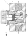
- All illustrated throttle valves 1 include a housing 2 with an inlet 3 and an outlet 4 for a fluidic Pressure medium, in particular compressed air.
- the inlet 3 and the Outlet 4 are further connected with means for connection Fluid lines equipped, in this case of internal threads are formed.
- inlet-side channel portion 6 denotes at least a first Fluid channel 7 in constant communication with the inlet.
- the inflow channel 5 circumferentially bounding Zuströmkanalwandung 8 is of a plurality of radially continuous outflow channels 11 interspersed. These outflow channels 11 open on the one hand with overflow openings 12 circumferentially in the inflow channel 5. On the other hand, they have at least a second one Fluid channel 13 with the outlet 4 in connection.
- the overflow openings 12 are over the length of the inflow channel 5 arranged distributed. Nevertheless, a simple connection to provide the discharge channels 11 to the outlet 4 extends around the Zuströmkanalwand 8 around a coaxial Annulus 14, in which the outflow channels 11 with their overflow 12 opposite openings open. This Annulus 14 is part of the second fluid channel 13, which makes the connection to the outlet 4.
- the throttle valve 1 further includes an elongated Throttle body 15, which is mounted on the housing 2, that it is linearly adjustable in the direction of its longitudinal axis 16 is.
- the throttle body 15 is for the throttling intensity the throttle valve 1 responsible by depending on from its current axial position one more or less large overflow cross section between the inlet 3 and the Outlet 4 releases.
- the case occupied by the throttle body 15 Positions are referred to as throttle positions.
- the throttle body 15 is arranged coaxially with the inflow channel 5. At one of its two axial-side end portions he provided with a cylindrical throttle piston 17, with the he from the inlet-side channel section 6 opposite outer end portion 18 of the inflow channel 5 forth in this Inflow channel 5 dips.
- the cross-sectional contour of the Throttling piston 17 corresponds at least substantially to that the inflow channel 5, so that the throttle body 15 in the interior the inflow channel 5 with the least possible radial play is arranged axially movable.
- the axial adjustment direction the throttle piston 17, which coincides with the longitudinal axis 16, is illustrated by double arrow 19.
- annular first sealing zone 20 Coaxial between the throttle piston 17 and the inner surface of the Inflow channel wall 8 is an annular first sealing zone 20 defined. It is defined in the embodiment by that circumferentially on the throttle piston 17 an annular Seal 22 is fixed, which at the inflow channel 8 slidably abuts. This first sealing zone 20 is located expediently in the immediate axial vicinity of the inlet-side channel section 6 of the inflow channel. 5 facing front end face 23 of the throttle piston 17th
- the throttle piston 17 thus provides the inflow channel 5 on the inlet side channel section 6 opposite Side tightly closing moving wall.
- this has the effect that depending on the respective throttle position of the inlet side channel section 6 towards released cross-section the overflow 12 varies.
- This cross-section presents the ensured by the throttle valve overflow cross section is, which flows from the inlet 3 to the outlet 4 Specifies fluid quantity.
- the axially distributed Arrangement of the overflow openings 12 is realized thereby, that the overflow openings 12 along an imaginary Helix along the circumference of the inflow channel 5 distributed are arranged. This also has the advantage that when needed realized axially overlapping overflow 12 can be.
- discharge channels 11 slit-like.
- length of the discharge channels in principle obviously, they could also be of very short wall openings be formed.
- the throttle valve 1 shows the throttle valve 1 in a closed position, in the provided overflow cross section between inlet 3 and outlet 4 is zero.
- the throttle body 15 is here so far immersed axially in the inflow channel 5, that the first sealing zone 20 between the overflow 12 and connected to the inlet 3 channel section 6 of the inflow channel 5 is arranged.
- the at the inlet 3 Pending pressure thus acts according to arrows 21 only on the front end surface 23 of the throttle piston 17, without to a the overflow 12 can get to.
- the figure 1 makes it clear that the exemplary throttle valve 1 the Advantage has, if necessary, the connection between the inlet. 3 and to interrupt the outlet 4 with reliable sealing.
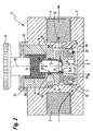
- FIG. 2 shows an arbitrary throttle position, in which the first sealing zone 20 so far in the direction of the outer end portion 18 of the inflow channel 5 is displaced that at least one of the overflow openings 12 at least partially with the inlet-side channel section 6 is in communication.
- the Pressure medium can therefore through the shared overflow flow out into the annular space 14 and from there to the outlet 4.
- a second sealing zone 24 is provided.
- Your Axial position with respect to the inflow channel 5 is always unchanged and it is realized, for example, by the fact that axially outside the overflow openings 12 a the throttle piston 17 under sealing coaxial enclosing annular Seal 25 is provided on the inflow channel 8.
- the illustrated in Figure 3 throttle valve 1 is consistent with that Figures 1 and 2 apart from the realization of the Outflow channels 11 match.
- the inflow channel wall 8 is here at least partially porous, wherein the pore-like fine spaces form the outflow channels 11 and after radially inward and radially outward open spaces the overflow 12 and the outer openings of the discharge channels 11 represent.
- the porous character of the inflow channel wall 8 for example, by an embodiment of sintered material, in particular sintered metal, can be realized, also plastic materials can be used.
- the porous region of the inflow channel wall 8 of a correspondingly structured annular body 26th formed, for example, by bonding with the rest Components of the inflow channel 8 may be connected.
- the illustrated throttle valves have the further advantage that the Zuströmkanalwandung 8 part of a in the housing 2 used valve cartridge 27 is.
- the housing 2 has via a recess 28 in which the valve cartridge 27 under Sealing firmly seated.
- At least one can be used for sealing contribute preferably molded seal 32, wherein at It should be mentioned that all the others are also included in this passage the throttle valve used reaching seals expediently are firmly formed on the associated carrier, for example, by an injection molding process.
- the valve cartridge 27 has the embodiment over an example cylindrical holding body 33, with the Zuströmkanalwandung 8 is in a fixed connection, the in the embodiment of a sleeve-like coaxial Extension 34 of the holding body 33 is formed.
- the extension 34 has a in Compared to the associated portion of the recess 28 lower Diameter, with the remaining space the above-mentioned annular space 14 forms.
- the valve cartridge 27 can in particular screwed or glued or preferably be pressed.
- the throttle valve according to the embodiments is as Throttle check valve designed. It has one By-pass channel 36, the 15 of the position of the throttle body is unaffected and a unidirectional fluidic parallel connection between inlet and outlet with respect to the discharge channels 11 causes. It leaves a return flow of the pressure medium from the outlet 4 to the inlet 3, while it is in the opposite direction locks.
- the additional check valve 37 realized in that between the outer periphery of the extension 34 and the inner periphery of the recess 28, a lip seal 38 is placed with flexible sealing lip 42. He is suitably fixed to the extension 34, wherein the flexurally elastic sealing lip 42 on the inner surface of the recess 28 is present. In this way, the lip seal forms 38 a part of the valve cartridge 27 and can together to be handled with this.
- the axial adjustment of the throttle body 15 with its throttle piston 17 is in the embodiments by a rotary actuator 43 causes.
- This is at the Embodiments of Figures 1 to 3 in a rotationally fixed connection with the throttle body 15, which in turn has a Threaded connection 44 mounted screwed in the holding body 33 is.
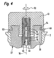
- the rotary actuator 43 rotates the throttle body 15 with and simultaneously becomes axial relocated. Since the change occurring in the supernatant the rotary actuator 43 with respect to the housing 2 is disadvantageous under certain conditions is determined by the FIG. 4 shows an alternative embodiment of the throttle body 15 associated rotary actuating means proposed.
- a rotary actuating member 43 is still provided provided, however, at the same time axially immovable on the holding body 33 is fixed.
- the throttle body 15 in turn is axially adjustable only in the context of a pure linear movement, by using anti-rotation means 45, his Do not interfere with axial movement, non-rotatable with respect to the holding body 33 is fixed.
- the anti-rotation devices 45 may be provided on the throttle body 15 longitudinal groove 46th in which a fixed to the holding body 33 securing projection 47 intervenes, or vice versa.
- a threaded connection 48 is provided between the rotary actuator 43 and the Throttle body 15.
- a threaded connection 48 is provided between the rotary actuator 43 and the Throttle body 15.
- further locking means 49 are provided, the one releasable stepwise fixing of the rotary actuator 43 allow in different rotational positions.
- the holding body 33 along a a circle or a circular arc extending locking teeth Be provided 53, in the at least one of the rotary actuator 43 provided latching projection 54 engages, or the other way around.
- the throttle valves of the embodiment allow the Realization of a linear behavior, such that the set Throttling intensity linear from the given Throttle position of the throttle piston 17 depends.
- a simple one Scale can be easily reproduced settings make, especially since the setting operations themselves not from Flow fluctuations are accompanied.
- valve cartridge 27 can be integrated into any housing, So for example, directly into the case of a fluidic drive, in particular in a function as a speed regulating valve.
- the throttle valves of the embodiment are for manual Act designed. But it would also be possible to interpret for fluidic - in particular pneumatic - and / or electrical actuation.
- the throttle body could in this Case a suitable fluidic and / or electrical actuator be assigned.
Landscapes
- Engineering & Computer Science (AREA)
- General Engineering & Computer Science (AREA)
- Mechanical Engineering (AREA)
- Sliding Valves (AREA)
- Details Of Valves (AREA)
- Lift Valve (AREA)
- Check Valves (AREA)
- Safety Valves (AREA)
- Control Of Fluid Pressure (AREA)
Description
- Figur 1
- eine erste Bauform des erfindungsgemäßen Drosselventils im Längsschnitt, wobei der Drosselkolben eine Schließstellung einnimmt, die ein Hindurchströmen des Druckmediums vom Einlaß zum Auslaß gänzlich verhindert,
- Figur 2
- das Drosselventil aus Figur 1 bei veränderter Axialposition des Drosselkörpers in einer ausgewählten Drosselstellung,
- Figur 3
- eine weitere Ausführungsform des Drosselventils in einer der Figur 1 entsprechenden Darstellungsweise, und
- Figur 4
- einen sich auf die Betätigungsmittel beziehenden Ausschnitt einer weiteren Ausführungsform des Drosselventils, wiederum im Längsschnitt.
Claims (15)
- Drosselventil, mit einem in Richtung seiner Längsachse (16) verstellbaren Drosselkörper (15), der in Abhängigkeit von seiner Drosselstellung zwischen einem Einlass (3) und einem Auslass (4) einen mehr oder weniger großen Überströmquerschnitt freigibt, wobei der Drosselkörper (15) einen zylindrischen Drosselkolben (17) aufweist, der in jeder Drosselstellung koaxial in einen mit dem Einlass (3) kommunizierenden Zuströmkanal (5) eintaucht, mit dessen Wandung (8) er im Bereich einer umfangsseitigen Abdichtzone (20) in ständigem Dichtkontakt steht, wobei die bezüglich dem zuströmkanal (5) eingenommene Axialposition der Abdichtzone (20) von der momentanen Drosselstellung abhängt, und wobei in der Wandung (8) des Zuströmkanals (5) einerseits mit dem Auslass (4) kommunizierende Ausströmkanäle (11) vorgesehen sind, die andererseits über entlang des Verstellweges der Abdichtzone (20) verteilte Überströmöffnungen (12) in den Zuströmkanal (5) münden, wobei der Überströmquerschnitt ausschließlich durch den vor der Abdichtzone (20) liegenden, zum einlassseitigen Abschnitt (6) des Zuströmkanals (5) hin freigegebenen Querschnitt der Überströmöffnungen (12) definiert wird.
- Drosselventil nach Anspruch 1, dadurch gekennzeichnet, daß die Ausströmkanäle (11) zumindest teilweise von einzelnen bohrungsartigen Kanälen gebildet sind.
- Drosselventil nach Anspruch 1 oder 2, dadurch gekennzeichnet, daß die Ausströmkanäle (11) zumindest teilweise schlitzartig ausgeführt sind.
- Drosselventil nach einem der Ansprüche 1 bis 3, dadurch gekennzeichnet, daß die Überströmöffnungen (12) entlang einer Schraubenlinie über den Umfang des Zuströmkanals (5) verteilt sind.
- Drosselventil nach einem der Ansprüche 1 bis 4, dadurch gekennzeichnet, daß die Ausströmkanäle (11) zumindest teilweise von den Zwischenräumen einer porösen Zuströmkanalwandung (8) gebildet sind.
- Drosselventil nach Anspruch 5, dadurch gekennzeichnet, daß die Zuströmkanalwandung (8) im Bereich der Ausströmkanäle (11) aus Sintermaterial besteht.
- Drosselventil nach einem der Ansprüche 1 bis 6, dadurch gekennzeichnet, daß koaxial um die Zuströmkanalwandung (8) herum ein Ringraum (14) definiert ist, in den zum einen die Ausströmkanäle (11) ausmünden und der zum anderen mit dem Auslaß (4) kommuniziert.
- Drosselventil nach einem der Ansprüche 1 bis 7, gekennzeichnet durch mindestens einen vom Drosselkörper (15) unbeeinflußten By-Pass-Kanal zwischen dem Einlaß (3) und dem Auslaß (4), in den ein zum Auslaß (4) hin sperrendes Rückschlagventil (37) eingeschaltet ist.
- Drosselventil nach Anspruch 8, dadurch gekennzeichnet, daß das Rückschlagventil (37) ein von der Zuströmkanalwandung (8) getragenes und vorzugsweise als Lippendichtring (38) ausgeführtes Ventilglied aufweist.
- Drosselventil nach einem der Ansprüche 1 bis 9, dadurch gekennzeichnet, daß die Zuströmkanalwandung (8) und der zugeordnete Drosselkörper (15) Bestandteil einer in ein Gehäuse (2) eingesetzten oder einsetzbaren Ventilpatrone (27) ist.
- Drosselventil nach Anspruch 10, dadurch gekennzeichnet, daß die Zuströmkanalwandung (8) ein in einem Haltekörper (33) der Ventilpatrone (27) verankertes Einsatzteil ist.
- Drosselventil nach einem der Ansprüche 1 bis 11, dadurch gekennzeichnet, daß zwischen der Zuströmkanalwandung (8) und dem Drosselkörper (15) auf der dem einlaßseitigen Abschnitt (6) des Zuströmkanals (5) axial entgegengesetzten Seite der Überströmöffnungen (12) eine weitere Abdichtzone (24) vorgesehen ist.
- Drosselventil nach einem der Ansprüche 1 bis 12, dadurch gekennzeichnet, daß dem Drosselkörper (15) zu seiner linearen Verstellung ein Drehbetätigungsglied (43) zugeordnet ist.
- Drosselventil nach Anspruch 13, dadurch gekennzeichnet, daß das Drehbetätigungsglied (43) drehbar und zugleich axial feststehend gelagert ist, während der Drosselkörper (15) drehfest und zugleich axial verschiebbar gelagert ist, wobei zwischen dem Drehbetätigungsglied (43) und dem Drosselkörper (15) eine Gewindeverbindung (48) vorliegt.
- Drosselventil nach Anspruch 13 oder 14, gekennzeichnet durch Rastmittel (49) zur lösbaren Fixierung des Drehbetätigungsgliedes (43) in unterschiedlichen Drehpositionen.
Applications Claiming Priority (2)
| Application Number | Priority Date | Filing Date | Title |
|---|---|---|---|
| DE19932982A DE19932982C2 (de) | 1999-07-14 | 1999-07-14 | Drosselventil |
| DE19932982 | 1999-07-14 |
Publications (3)
| Publication Number | Publication Date |
|---|---|
| EP1069353A2 EP1069353A2 (de) | 2001-01-17 |
| EP1069353A3 EP1069353A3 (de) | 2002-07-31 |
| EP1069353B1 true EP1069353B1 (de) | 2005-04-06 |
Family
ID=7914769
Family Applications (1)
| Application Number | Title | Priority Date | Filing Date |
|---|---|---|---|
| EP00112741A Expired - Lifetime EP1069353B1 (de) | 1999-07-14 | 2000-06-16 | Drosselventil |
Country Status (3)
| Country | Link |
|---|---|
| US (1) | US6325101B1 (de) |
| EP (1) | EP1069353B1 (de) |
| DE (2) | DE19932982C2 (de) |
Cited By (1)
| Publication number | Priority date | Publication date | Assignee | Title |
|---|---|---|---|---|
| CN105156726A (zh) * | 2015-08-28 | 2015-12-16 | 芜湖市汽车产业技术研究院有限公司 | 一种气动顺序阀 |
Families Citing this family (15)
| Publication number | Priority date | Publication date | Assignee | Title |
|---|---|---|---|---|
| DE10134972A1 (de) | 2001-07-24 | 2003-02-20 | Demag Cranes & Components Gmbh | Durchlassventil für Strömungsmedium, insbesondere ein pneumatisches Drosselventil |
| DE10336669B3 (de) * | 2003-08-09 | 2005-02-24 | Festo Ag & Co.Kg | Drosselventil |
| JP4864876B2 (ja) * | 2004-04-22 | 2012-02-01 | アイス エナジー インコーポレーテッド | 冷媒の圧力および流量を調節するための閉鎖システムならびに冷媒の圧力および流量を制御する方法 |
| US20060049375A1 (en) * | 2004-09-07 | 2006-03-09 | Fisher Controls International Llc | Boronized valve seal |
| US7373951B2 (en) * | 2004-09-07 | 2008-05-20 | Fisher Controls International Llc | Control valve having “C” seal |
| DE102006016197A1 (de) * | 2006-04-06 | 2007-10-18 | Festo Ag & Co | Fluidtechnisches Gerät |
| US9056701B1 (en) | 2012-05-22 | 2015-06-16 | Sypris Technologies, Inc. | Tool-less closure |
| US8596484B1 (en) | 2012-05-22 | 2013-12-03 | Sypris Technologies, Inc. | Tool-less closure |
| DE102012209617A1 (de) * | 2012-06-08 | 2013-12-12 | Robert Bosch Gmbh | Druckablassvorrichtung |
| US9097346B1 (en) | 2013-03-15 | 2015-08-04 | Sypris Technologies, Inc. | Closure lip seal relief |
| DE102013010239B4 (de) * | 2013-06-18 | 2023-06-29 | Festo Se & Co. Kg | Ventileinrichtung für abrasive Fluide und/oder fluidisierbare Pulvermaterialien |
| CN105546132A (zh) * | 2016-03-04 | 2016-05-04 | 苏州道森钻采设备股份有限公司 | 一种全关闭密封式孔板节流阀 |
| US10941870B1 (en) | 2016-12-12 | 2021-03-09 | Agi Industries, Inc. | Fluid throttling valve |
| US10344891B1 (en) | 2016-12-12 | 2019-07-09 | Agi Industries, Inc. | Fluid throttling valve |
| CN115614489B (zh) * | 2022-12-16 | 2023-03-14 | 中国空气动力研究与发展中心超高速空气动力研究所 | 可重复测试的瞬移气动装置及应用方法 |
Family Cites Families (13)
| Publication number | Priority date | Publication date | Assignee | Title |
|---|---|---|---|---|
| FR1291716A (fr) * | 1961-03-16 | 1962-04-27 | Sourdillon Ets | Perfectionnements apportés aux robinets notamment du type à pointeau |
| US4041982A (en) * | 1976-01-09 | 1977-08-16 | Kieley & Mueller, Inc. | Double wall plug control valve |
| DE3903781A1 (de) * | 1989-02-09 | 1990-08-16 | Festo Kg | Ventil |
| US5261453A (en) * | 1989-02-13 | 1993-11-16 | System Engineering And Components International B.V. | Valve provided with sound-reducing means |
| US5141028A (en) * | 1990-06-11 | 1992-08-25 | Solly Cohen | Valve assembly |
| US5113908A (en) * | 1990-09-04 | 1992-05-19 | Dresser Industries, Inc. | Multistep trim design |
| CA2031609C (en) * | 1990-12-05 | 1997-10-28 | Gregory Daniel William Pelech | Valve |
| SE469088B (sv) * | 1991-09-23 | 1993-05-10 | Vattenfall Utveckling Ab | Ventil foer reglering och/eller avstaengning av floedet av en vaetska i en ledning |
| JPH073263B2 (ja) * | 1992-10-09 | 1995-01-18 | 日本ベーレー株式会社 | 高差圧調節弁 |
| US5337784A (en) * | 1992-10-26 | 1994-08-16 | E-Z Dispensers, Inc. | Flow control valve |
| US5516079A (en) * | 1995-01-27 | 1996-05-14 | Baumann Hans D | Small flow control valve with tight shutoff capability |
| AUPO412896A0 (en) * | 1996-12-11 | 1997-01-09 | Upham, John D. | Electromagnetic gas injection valve |
| DE19748343C2 (de) * | 1997-11-03 | 2001-11-22 | Danfoss As | Hydraulikventil |
-
1999
- 1999-07-14 DE DE19932982A patent/DE19932982C2/de not_active Expired - Fee Related
-
2000
- 2000-06-16 DE DE50009963T patent/DE50009963D1/de not_active Expired - Lifetime
- 2000-06-16 EP EP00112741A patent/EP1069353B1/de not_active Expired - Lifetime
- 2000-07-12 US US09/614,848 patent/US6325101B1/en not_active Expired - Fee Related
Cited By (1)
| Publication number | Priority date | Publication date | Assignee | Title |
|---|---|---|---|---|
| CN105156726A (zh) * | 2015-08-28 | 2015-12-16 | 芜湖市汽车产业技术研究院有限公司 | 一种气动顺序阀 |
Also Published As
| Publication number | Publication date |
|---|---|
| US6325101B1 (en) | 2001-12-04 |
| DE19932982A1 (de) | 2001-01-25 |
| DE19932982C2 (de) | 2003-02-13 |
| EP1069353A2 (de) | 2001-01-17 |
| EP1069353A3 (de) | 2002-07-31 |
| DE50009963D1 (de) | 2005-05-12 |
Similar Documents
| Publication | Publication Date | Title |
|---|---|---|
| EP1069353B1 (de) | Drosselventil | |
| DE2645948C2 (de) | Rückspülbare Filtereinrichtung | |
| DE69517363T2 (de) | Anordnung in Regelventilen | |
| DE202018006847U1 (de) | Fluiddämpfer für gegeneinander verstellbare Körper mit einem in einem Zylinder verstellbar geführten Kolben | |
| DE4340184A1 (de) | Spritzdüse, insbesondere für Hochdruckreinigungsgeräte | |
| EP0321774B1 (de) | Schiebeventil mit Mengenregulierung | |
| DE3503434A1 (de) | Regelventil | |
| DE3226696C2 (de) | ||
| EP0358899B1 (de) | Drosselrückschlagventil | |
| AT405675B (de) | Vorrichtung zur begrenzung der vorspannung einer regelfeder | |
| EP1336789B1 (de) | Drosselventil | |
| DE69124977T2 (de) | Durchflussregler | |
| DE2852935C2 (de) | Thermostatventil | |
| DE69300578T2 (de) | Verbesserungen von thermostatischen Kappen und Mischungsventilen mit solchen Kappen. | |
| DE4033301C2 (de) | Entlastungsventil | |
| EP1520080A1 (de) | Regulierventil für einen türschliesser oder hydraulischen drehflügelantrieb | |
| DE69008266T2 (de) | Elektromagnetisches Ventil. | |
| DE3031284A1 (de) | Durchflussmesser. | |
| EP3599399A1 (de) | Sanitärventil mit membranventil | |
| DE3612752C2 (de) | Drosselvorrichtung | |
| DE102011015781A1 (de) | Drosselventil | |
| DE10049091B4 (de) | Drosselventil | |
| EP0731305B1 (de) | Pneumatisches Sicherheitsventil | |
| DE10336669B3 (de) | Drosselventil | |
| DE112020001778T5 (de) | Thermostatischer Einsatz |
Legal Events
| Date | Code | Title | Description |
|---|---|---|---|
| PUAI | Public reference made under article 153(3) epc to a published international application that has entered the european phase |
Free format text: ORIGINAL CODE: 0009012 |
|
| AK | Designated contracting states |
Kind code of ref document: A2 Designated state(s): AT BE CH CY DE DK ES FI FR GB GR IE IT LI LU MC NL PT SE |
|
| AX | Request for extension of the european patent |
Free format text: AL;LT;LV;MK;RO;SI |
|
| PUAL | Search report despatched |
Free format text: ORIGINAL CODE: 0009013 |
|
| AK | Designated contracting states |
Kind code of ref document: A3 Designated state(s): AT BE CH CY DE DK ES FI FR GB GR IE IT LI LU MC NL PT SE |
|
| AX | Request for extension of the european patent |
Free format text: AL;LT;LV;MK;RO;SI |
|
| RIC1 | Information provided on ipc code assigned before grant |
Free format text: 7F 16K 1/52 A, 7F 16K 47/08 B, 7F 16K 15/18 B |
|
| 17P | Request for examination filed |
Effective date: 20021029 |
|
| AKX | Designation fees paid |
Designated state(s): CH DE FR IT LI NL |
|
| 17Q | First examination report despatched |
Effective date: 20040614 |
|
| GRAP | Despatch of communication of intention to grant a patent |
Free format text: ORIGINAL CODE: EPIDOSNIGR1 |
|
| GRAS | Grant fee paid |
Free format text: ORIGINAL CODE: EPIDOSNIGR3 |
|
| GRAA | (expected) grant |
Free format text: ORIGINAL CODE: 0009210 |
|
| AK | Designated contracting states |
Kind code of ref document: B1 Designated state(s): CH DE FR IT LI NL |
|
| REG | Reference to a national code |
Ref country code: CH Ref legal event code: NV Representative=s name: TROESCH SCHEIDEGGER WERNER AG Ref country code: CH Ref legal event code: EP |
|
| REG | Reference to a national code |
Ref country code: IE Ref legal event code: FG4D Free format text: LANGUAGE OF EP DOCUMENT: GERMAN |
|
| REF | Corresponds to: |
Ref document number: 50009963 Country of ref document: DE Date of ref document: 20050512 Kind code of ref document: P |
|
| PLBE | No opposition filed within time limit |
Free format text: ORIGINAL CODE: 0009261 |
|
| STAA | Information on the status of an ep patent application or granted ep patent |
Free format text: STATUS: NO OPPOSITION FILED WITHIN TIME LIMIT |
|
| ET | Fr: translation filed | ||
| 26N | No opposition filed |
Effective date: 20060110 |
|
| PGFP | Annual fee paid to national office [announced via postgrant information from national office to epo] |
Ref country code: NL Payment date: 20080618 Year of fee payment: 9 |
|
| NLV4 | Nl: lapsed or anulled due to non-payment of the annual fee |
Effective date: 20100101 |
|
| PG25 | Lapsed in a contracting state [announced via postgrant information from national office to epo] |
Ref country code: NL Free format text: LAPSE BECAUSE OF NON-PAYMENT OF DUE FEES Effective date: 20100101 |
|
| PGFP | Annual fee paid to national office [announced via postgrant information from national office to epo] |
Ref country code: CH Payment date: 20110728 Year of fee payment: 12 |
|
| PGFP | Annual fee paid to national office [announced via postgrant information from national office to epo] |
Ref country code: FR Payment date: 20120705 Year of fee payment: 13 |
|
| PGFP | Annual fee paid to national office [announced via postgrant information from national office to epo] |
Ref country code: IT Payment date: 20120619 Year of fee payment: 13 |
|
| REG | Reference to a national code |
Ref country code: CH Ref legal event code: PL |
|
| REG | Reference to a national code |
Ref country code: FR Ref legal event code: ST Effective date: 20140228 |
|
| PG25 | Lapsed in a contracting state [announced via postgrant information from national office to epo] |
Ref country code: CH Free format text: LAPSE BECAUSE OF NON-PAYMENT OF DUE FEES Effective date: 20130630 Ref country code: LI Free format text: LAPSE BECAUSE OF NON-PAYMENT OF DUE FEES Effective date: 20130630 |
|
| PG25 | Lapsed in a contracting state [announced via postgrant information from national office to epo] |
Ref country code: IT Free format text: LAPSE BECAUSE OF NON-PAYMENT OF DUE FEES Effective date: 20130616 Ref country code: FR Free format text: LAPSE BECAUSE OF NON-PAYMENT OF DUE FEES Effective date: 20130701 |
|
| PGFP | Annual fee paid to national office [announced via postgrant information from national office to epo] |
Ref country code: DE Payment date: 20140423 Year of fee payment: 15 |
|
| REG | Reference to a national code |
Ref country code: DE Ref legal event code: R119 Ref document number: 50009963 Country of ref document: DE |
|
| PG25 | Lapsed in a contracting state [announced via postgrant information from national office to epo] |
Ref country code: DE Free format text: LAPSE BECAUSE OF NON-PAYMENT OF DUE FEES Effective date: 20160101 |