EP1069349B1 - Mehrgängiges, automatisches Getriebe ohne Drehmomentwandler - Google Patents
Mehrgängiges, automatisches Getriebe ohne Drehmomentwandler Download PDFInfo
- Publication number
- EP1069349B1 EP1069349B1 EP00305909A EP00305909A EP1069349B1 EP 1069349 B1 EP1069349 B1 EP 1069349B1 EP 00305909 A EP00305909 A EP 00305909A EP 00305909 A EP00305909 A EP 00305909A EP 1069349 B1 EP1069349 B1 EP 1069349B1
- Authority
- EP
- European Patent Office
- Prior art keywords
- clutch
- torque
- transmission
- engine
- pressure
- Prior art date
- Legal status (The legal status is an assumption and is not a legal conclusion. Google has not performed a legal analysis and makes no representation as to the accuracy of the status listed.)
- Expired - Lifetime
Links
- 230000005540 biological transmission Effects 0.000 title claims abstract description 77
- 238000002485 combustion reaction Methods 0.000 claims abstract description 8
- 230000000694 effects Effects 0.000 claims description 6
- 239000012530 fluid Substances 0.000 claims description 6
- 230000001133 acceleration Effects 0.000 description 8
- 230000001970 hydrokinetic effect Effects 0.000 description 8
- 238000002955 isolation Methods 0.000 description 7
- 238000010586 diagram Methods 0.000 description 6
- 230000006870 function Effects 0.000 description 6
- 230000008878 coupling Effects 0.000 description 4
- 238000010168 coupling process Methods 0.000 description 4
- 238000005859 coupling reaction Methods 0.000 description 4
- 230000007935 neutral effect Effects 0.000 description 4
- 238000010276 construction Methods 0.000 description 2
- 230000001276 controlling effect Effects 0.000 description 2
- 238000005461 lubrication Methods 0.000 description 2
- 238000012986 modification Methods 0.000 description 2
- 230000004048 modification Effects 0.000 description 2
- 239000003921 oil Substances 0.000 description 2
- 230000001105 regulatory effect Effects 0.000 description 2
- 230000004044 response Effects 0.000 description 2
- 239000013589 supplement Substances 0.000 description 2
- 238000013459 approach Methods 0.000 description 1
- 230000008859 change Effects 0.000 description 1
- 238000013016 damping Methods 0.000 description 1
- 230000003111 delayed effect Effects 0.000 description 1
- 238000006073 displacement reaction Methods 0.000 description 1
- 239000010687 lubricating oil Substances 0.000 description 1
- 238000004806 packaging method and process Methods 0.000 description 1
- 230000001360 synchronised effect Effects 0.000 description 1
- 230000007704 transition Effects 0.000 description 1
Images


Classifications
-
- F—MECHANICAL ENGINEERING; LIGHTING; HEATING; WEAPONS; BLASTING
- F16—ENGINEERING ELEMENTS AND UNITS; GENERAL MEASURES FOR PRODUCING AND MAINTAINING EFFECTIVE FUNCTIONING OF MACHINES OR INSTALLATIONS; THERMAL INSULATION IN GENERAL
- F16H—GEARING
- F16H61/00—Control functions within control units of change-speed- or reversing-gearings for conveying rotary motion ; Control of exclusively fluid gearing, friction gearing, gearings with endless flexible members or other particular types of gearing
- F16H61/12—Detecting malfunction or potential malfunction, e.g. fail safe ; Circumventing or fixing failures
-
- F—MECHANICAL ENGINEERING; LIGHTING; HEATING; WEAPONS; BLASTING
- F16—ENGINEERING ELEMENTS AND UNITS; GENERAL MEASURES FOR PRODUCING AND MAINTAINING EFFECTIVE FUNCTIONING OF MACHINES OR INSTALLATIONS; THERMAL INSULATION IN GENERAL
- F16H—GEARING
- F16H3/00—Toothed gearings for conveying rotary motion with variable gear ratio or for reversing rotary motion
- F16H3/44—Toothed gearings for conveying rotary motion with variable gear ratio or for reversing rotary motion using gears having orbital motion
- F16H3/62—Gearings having three or more central gears
- F16H3/66—Gearings having three or more central gears composed of a number of gear trains without drive passing from one train to another
-
- F—MECHANICAL ENGINEERING; LIGHTING; HEATING; WEAPONS; BLASTING
- F16—ENGINEERING ELEMENTS AND UNITS; GENERAL MEASURES FOR PRODUCING AND MAINTAINING EFFECTIVE FUNCTIONING OF MACHINES OR INSTALLATIONS; THERMAL INSULATION IN GENERAL
- F16H—GEARING
- F16H61/00—Control functions within control units of change-speed- or reversing-gearings for conveying rotary motion ; Control of exclusively fluid gearing, friction gearing, gearings with endless flexible members or other particular types of gearing
- F16H61/02—Control functions within control units of change-speed- or reversing-gearings for conveying rotary motion ; Control of exclusively fluid gearing, friction gearing, gearings with endless flexible members or other particular types of gearing characterised by the signals used
- F16H61/0202—Control functions within control units of change-speed- or reversing-gearings for conveying rotary motion ; Control of exclusively fluid gearing, friction gearing, gearings with endless flexible members or other particular types of gearing characterised by the signals used the signals being electric
- F16H61/0204—Control functions within control units of change-speed- or reversing-gearings for conveying rotary motion ; Control of exclusively fluid gearing, friction gearing, gearings with endless flexible members or other particular types of gearing characterised by the signals used the signals being electric for gearshift control, e.g. control functions for performing shifting or generation of shift signal
- F16H61/0206—Layout of electro-hydraulic control circuits, e.g. arrangement of valves
-
- F—MECHANICAL ENGINEERING; LIGHTING; HEATING; WEAPONS; BLASTING
- F16—ENGINEERING ELEMENTS AND UNITS; GENERAL MEASURES FOR PRODUCING AND MAINTAINING EFFECTIVE FUNCTIONING OF MACHINES OR INSTALLATIONS; THERMAL INSULATION IN GENERAL
- F16H—GEARING
- F16H61/00—Control functions within control units of change-speed- or reversing-gearings for conveying rotary motion ; Control of exclusively fluid gearing, friction gearing, gearings with endless flexible members or other particular types of gearing
- F16H61/02—Control functions within control units of change-speed- or reversing-gearings for conveying rotary motion ; Control of exclusively fluid gearing, friction gearing, gearings with endless flexible members or other particular types of gearing characterised by the signals used
- F16H61/0202—Control functions within control units of change-speed- or reversing-gearings for conveying rotary motion ; Control of exclusively fluid gearing, friction gearing, gearings with endless flexible members or other particular types of gearing characterised by the signals used the signals being electric
- F16H61/0204—Control functions within control units of change-speed- or reversing-gearings for conveying rotary motion ; Control of exclusively fluid gearing, friction gearing, gearings with endless flexible members or other particular types of gearing characterised by the signals used the signals being electric for gearshift control, e.g. control functions for performing shifting or generation of shift signal
- F16H61/0246—Control functions within control units of change-speed- or reversing-gearings for conveying rotary motion ; Control of exclusively fluid gearing, friction gearing, gearings with endless flexible members or other particular types of gearing characterised by the signals used the signals being electric for gearshift control, e.g. control functions for performing shifting or generation of shift signal characterised by initiating reverse gearshift
-
- F—MECHANICAL ENGINEERING; LIGHTING; HEATING; WEAPONS; BLASTING
- F16—ENGINEERING ELEMENTS AND UNITS; GENERAL MEASURES FOR PRODUCING AND MAINTAINING EFFECTIVE FUNCTIONING OF MACHINES OR INSTALLATIONS; THERMAL INSULATION IN GENERAL
- F16H—GEARING
- F16H59/00—Control inputs to control units of change-speed- or reversing-gearings for conveying rotary motion
- F16H59/36—Inputs being a function of speed
- F16H2059/366—Engine or motor speed
-
- F—MECHANICAL ENGINEERING; LIGHTING; HEATING; WEAPONS; BLASTING
- F16—ENGINEERING ELEMENTS AND UNITS; GENERAL MEASURES FOR PRODUCING AND MAINTAINING EFFECTIVE FUNCTIONING OF MACHINES OR INSTALLATIONS; THERMAL INSULATION IN GENERAL
- F16H—GEARING
- F16H61/00—Control functions within control units of change-speed- or reversing-gearings for conveying rotary motion ; Control of exclusively fluid gearing, friction gearing, gearings with endless flexible members or other particular types of gearing
- F16H61/12—Detecting malfunction or potential malfunction, e.g. fail safe ; Circumventing or fixing failures
- F16H2061/1204—Detecting malfunction or potential malfunction, e.g. fail safe ; Circumventing or fixing failures for malfunction caused by simultaneous engagement of different ratios resulting in transmission lock state or tie-up condition
-
- F—MECHANICAL ENGINEERING; LIGHTING; HEATING; WEAPONS; BLASTING
- F16—ENGINEERING ELEMENTS AND UNITS; GENERAL MEASURES FOR PRODUCING AND MAINTAINING EFFECTIVE FUNCTIONING OF MACHINES OR INSTALLATIONS; THERMAL INSULATION IN GENERAL
- F16H—GEARING
- F16H61/00—Control functions within control units of change-speed- or reversing-gearings for conveying rotary motion ; Control of exclusively fluid gearing, friction gearing, gearings with endless flexible members or other particular types of gearing
- F16H61/12—Detecting malfunction or potential malfunction, e.g. fail safe ; Circumventing or fixing failures
- F16H2061/1232—Bringing the control into a predefined state, e.g. giving priority to particular actuators or gear ratios
-
- F—MECHANICAL ENGINEERING; LIGHTING; HEATING; WEAPONS; BLASTING
- F16—ENGINEERING ELEMENTS AND UNITS; GENERAL MEASURES FOR PRODUCING AND MAINTAINING EFFECTIVE FUNCTIONING OF MACHINES OR INSTALLATIONS; THERMAL INSULATION IN GENERAL
- F16H—GEARING
- F16H61/00—Control functions within control units of change-speed- or reversing-gearings for conveying rotary motion ; Control of exclusively fluid gearing, friction gearing, gearings with endless flexible members or other particular types of gearing
- F16H61/12—Detecting malfunction or potential malfunction, e.g. fail safe ; Circumventing or fixing failures
- F16H2061/1256—Detecting malfunction or potential malfunction, e.g. fail safe ; Circumventing or fixing failures characterised by the parts or units where malfunctioning was assumed or detected
- F16H2061/1292—Detecting malfunction or potential malfunction, e.g. fail safe ; Circumventing or fixing failures characterised by the parts or units where malfunctioning was assumed or detected the failing part is the power supply, e.g. the electric power supply
-
- F—MECHANICAL ENGINEERING; LIGHTING; HEATING; WEAPONS; BLASTING
- F16—ENGINEERING ELEMENTS AND UNITS; GENERAL MEASURES FOR PRODUCING AND MAINTAINING EFFECTIVE FUNCTIONING OF MACHINES OR INSTALLATIONS; THERMAL INSULATION IN GENERAL
- F16H—GEARING
- F16H2200/00—Transmissions for multiple ratios
- F16H2200/003—Transmissions for multiple ratios characterised by the number of forward speeds
- F16H2200/0043—Transmissions for multiple ratios characterised by the number of forward speeds the gear ratios comprising four forward speeds
-
- F—MECHANICAL ENGINEERING; LIGHTING; HEATING; WEAPONS; BLASTING
- F16—ENGINEERING ELEMENTS AND UNITS; GENERAL MEASURES FOR PRODUCING AND MAINTAINING EFFECTIVE FUNCTIONING OF MACHINES OR INSTALLATIONS; THERMAL INSULATION IN GENERAL
- F16H—GEARING
- F16H2312/00—Driving activities
- F16H2312/02—Driving off
-
- F—MECHANICAL ENGINEERING; LIGHTING; HEATING; WEAPONS; BLASTING
- F16—ENGINEERING ELEMENTS AND UNITS; GENERAL MEASURES FOR PRODUCING AND MAINTAINING EFFECTIVE FUNCTIONING OF MACHINES OR INSTALLATIONS; THERMAL INSULATION IN GENERAL
- F16H—GEARING
- F16H2312/00—Driving activities
- F16H2312/20—Start-up or shut-down
-
- F—MECHANICAL ENGINEERING; LIGHTING; HEATING; WEAPONS; BLASTING
- F16—ENGINEERING ELEMENTS AND UNITS; GENERAL MEASURES FOR PRODUCING AND MAINTAINING EFFECTIVE FUNCTIONING OF MACHINES OR INSTALLATIONS; THERMAL INSULATION IN GENERAL
- F16H—GEARING
- F16H57/00—General details of gearing
- F16H57/0006—Vibration-damping or noise reducing means specially adapted for gearings
-
- F—MECHANICAL ENGINEERING; LIGHTING; HEATING; WEAPONS; BLASTING
- F16—ENGINEERING ELEMENTS AND UNITS; GENERAL MEASURES FOR PRODUCING AND MAINTAINING EFFECTIVE FUNCTIONING OF MACHINES OR INSTALLATIONS; THERMAL INSULATION IN GENERAL
- F16H—GEARING
- F16H61/00—Control functions within control units of change-speed- or reversing-gearings for conveying rotary motion ; Control of exclusively fluid gearing, friction gearing, gearings with endless flexible members or other particular types of gearing
- F16H61/02—Control functions within control units of change-speed- or reversing-gearings for conveying rotary motion ; Control of exclusively fluid gearing, friction gearing, gearings with endless flexible members or other particular types of gearing characterised by the signals used
- F16H61/0262—Control functions within control units of change-speed- or reversing-gearings for conveying rotary motion ; Control of exclusively fluid gearing, friction gearing, gearings with endless flexible members or other particular types of gearing characterised by the signals used the signals being hydraulic
- F16H61/0276—Elements specially adapted for hydraulic control units, e.g. valves
- F16H61/0283—Governor valves
-
- F—MECHANICAL ENGINEERING; LIGHTING; HEATING; WEAPONS; BLASTING
- F16—ENGINEERING ELEMENTS AND UNITS; GENERAL MEASURES FOR PRODUCING AND MAINTAINING EFFECTIVE FUNCTIONING OF MACHINES OR INSTALLATIONS; THERMAL INSULATION IN GENERAL
- F16H—GEARING
- F16H61/00—Control functions within control units of change-speed- or reversing-gearings for conveying rotary motion ; Control of exclusively fluid gearing, friction gearing, gearings with endless flexible members or other particular types of gearing
- F16H61/68—Control functions within control units of change-speed- or reversing-gearings for conveying rotary motion ; Control of exclusively fluid gearing, friction gearing, gearings with endless flexible members or other particular types of gearing specially adapted for stepped gearings
- F16H61/684—Control functions within control units of change-speed- or reversing-gearings for conveying rotary motion ; Control of exclusively fluid gearing, friction gearing, gearings with endless flexible members or other particular types of gearing specially adapted for stepped gearings without interruption of drive
- F16H61/686—Control functions within control units of change-speed- or reversing-gearings for conveying rotary motion ; Control of exclusively fluid gearing, friction gearing, gearings with endless flexible members or other particular types of gearing specially adapted for stepped gearings without interruption of drive with orbital gears
Definitions
- the invention which is claimed in independent claim 1 relates to automotive vehicle drivelines having an internal combustion engine and multiple-ratio gearing wherein the engine is connected drivably to torque input elements of the gearing without requiring a hydrokinetic torque converter.
- a multiple-ratio automatic transmission of the kind shown, for example, in U.S. Patent 4,938,097, a multiple-ratio transmission is situated on the torque output side of the hydrokinetic torque converter, the impeller of the converter being connected through the driveline damper to the crankshaft of an internal combustion engine.
- the turbine of the torque converter is connected to a torque input element of the gearing through a selectively engageable forward-drive friction clutch during operation in forward drive.
- a separate reverse drive friction clutch connects the turbine of the torque converter to another torque input element of the gearing during operation in reverse.
- the torque converter of such known transmissions occupies a substantial space in the driveline assembly between the transmission gearing and the engine. It also is of a relatively large diameter relative to the diameter of the transmission gearing. Further, the converter has a substantial rotating mass, which must be accelerated by the engine during startup of the vehicle in forward drive or in reverse drive.
- the effective mass of the converter includes the mass of the hydraulic fluid that circulates in the torus circuit defined by the converter impeller, the turbine and the stator.
- the operating efficiency of the converter during startup is low. It varies from a zero value at stall to a maximum value of approximately 80-85% at the coupling point.
- the coupling point occurs at the transition from the torque multiplication mode to the coupling mode where the torque multiplication ratio is unity.
- the converter inefficiency results in power loss, which is manifested by an increase in temperature of the hydrokinetic fluid. This necessitates the use of oil coolers, which further add to the gross weight of the transmission assembly and which require additional packaging space for the automotive vehicle driveline.
- the torque converter functions, as indicated above, to provide a smooth launch of the vehicle from a standing start. It also disconnects the engine from the driveline when the vehicle is at rest.
- a third principal function is the dampening of engine torsional vibrations.
- the invention is concerned with a driveline with a converterless transmission in which the torque is delivered directly from the crankshaft of an internal combustion engine to the torque input element of multiple-ratio gearing.
- the invention seeks to provide vehicle launch advantages of a torque converter transmission, as described above, without requiring a torque converter as part of the transmission assembly yet using a normal low gear ratio for starting. In this way, the torque converter inefficiencies in the delivery of torque to the vehicle traction wheels can be avoided.
- a converterless multiple-ratio automatic transmission of a vehicle driveline having an internal combustion engine including a driven shaft in a torque flow path to vehicle traction wheels; planetary gearing of the transmission defining multiple forward drive torque flow paths between the engine and the driven shaft; a torque input element of the gearing directly connectable to be driven by the engine crankshaft, whereby the crankshaft and the torque input element are continuously coupled during torque delivery through the torque flow paths for rotation in unison; pressure-operated friction clutch means in the transmission for establishing and disestablishing the torque flow paths including a forward drive clutch that is engaged for forward drive operation; and automatic clutch control means for disengaging and engaging the forward drive clutch to respectively disconnect and connect the engine from and to the gearing, thereby effecting control of the driveline during vehicle startup in forward drive; characterised in that the clutch control means comprises a line pressure pump connected to the torque input element of the gearing; and a control valve circuit means including an electronic processor and a manually operable range selector valve for distributing pressure generated by
- the planetary gearing of the transmission further defines a reverse drive torque flow path between the engine and the driven shaft; and the automatic clutch control means effects control of the driveline during vehicle startup in reverse drive.
- the engine may be disconnected from the driveline by an appropriate neutral-idle type control of the forward or reverse clutches. This is accomplished without the requirement for using a startup clutch intermediate the engine crankshaft and the transmission gearing. The inertia that otherwise would be introduced by the use of a separate startup clutch is avoided, which permits a faster response at the vehicle wheels to a command for startup torque delivered to the engine by the operator through use of an engine throttle.
- Torsional isolation which normally would be provided by a hydrokinetic torque converter, can be obtained with the invention by continuously slipping a friction element of the clutch and brake system for the gearing.
- the slipping element may be the forward clutch.
- the forward clutch or the direct clutch can be used.
- the slipping element may be the direct clutch.
- the reverse clutch may be used.
- the preferred embodiment of the invention includes a hydraulic valve system using variable force solenoid valves for controlling the forward and reverse drive modes, the direct-drive ratio, the second and fourth drive ratios, and the low-and-reverse drive ratios.
- variable force solenoid valves for controlling the forward and reverse drive modes, the direct-drive ratio, the second and fourth drive ratios, and the low-and-reverse drive ratios.
- the low-and-reverse variable force solenoid will provide zero pressure.
- a shuttle valve responds to the loss of low-and-reverse variable force solenoid pressure, thereby making available engine pitot tube pressure, which provides a pressure for engaging the clutches and brakes of the transmission as a function of engine speed squared. In this way, a so-called "limp home" capability is achieved.
- Loss of electric power will cause the system to default to third gear during operation of the forward drive ranges and to default to reverse drive when reverse drive range is selected by the operator.
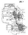
- Figure 1 shows in schematic form a multiple-ratio automatic transmission identified by reference numeral 10 and an internal combustion engine 12.
- the engine 12 includes a crankshaft 14, which is coupled to a torque input shaft 16 for the transmission 10. That coupling is achieved by a damper assembly 18 of conventional construction.
- the torque input side of the damper 18 may be connected to the crankshaft 14 by a drive plate 20.
- the transmission 10 includes a first planetary gearset 22 and a second planetary gear set 24.
- Ring gear 26 of the gearset 24 defines a drive sprocket for a drive chain 28, which extends to driven sprocket 30 of a final drive planetary gear unit 32.
- the torque input gear element of planetary gear unit 32 is ring gear 34, which is engaged by planetary pinions 36.
- the ring gear 38 of the gear unit 32 is anchored to transmission housing 40.
- the carrier for the planetary pinions 36 drives the differential carrier 42 of a differential gear unit 44.
- Planetary bevel pinions 46 on the carrier 42 engage each of two side gears 48 and 50.
- Each side gear 48 and 50 is connected drivably to an axle half shaft, as shown at 52 and 54, respectively.
- Each axle half shaft is connected to a vehicle traction wheel.
- the planetary transmission includes a reverse clutch 56, a direct-drive clutch 58, and a forward-drive clutch 60.
- the function of these clutches will be described generally with reference to the schematic diagram of Figure 1a.
- the engine crankshaft 14 is connected to torque input shaft 16, which transfers torque to sun gear 62 of the planetary gear unit 22 through forward clutch 60, which is engaged during operation in each of the first three forward driving gear ratios.
- Input shaft 16 is connected through direct clutch 58 to a ring gear 64 during operation in the third forward driving speed ratio.
- the torque of the ring gear 64 is transferred through the planetary carrier of gear unit 24.
- the carrier for gear unit 64 is connected to ring gear 26 of the gear unit 24.
- Torque input shaft 16 is connected through the reverse clutch 56 to the sun gear 66 of the gear unit 24.
- the carrier for the gear unit 24 is selectively anchored by a low-and-reverse disc brake 68 during reverse drive and during low-speed ratio operation.
- FIG 1b shows the clutch and brake engagement and release pattern for the clutches and brakes shown in Figure 1a.
- the clutches and brakes are engaged and released selectively to establish each of four forward-driving ratios and a single reverse ratio.
- the symbols RC, FC, DC, L/R and 2/4, indicated in Figure 4 designate the clutches and brakes that are similarly designated in Figure 1a.
- These clutches and brakes are identified by reference numerals 56, 60, 58, 68 and 70, respectively.
- Brake 70 anchors sun gear 66 during second ratio operation and fourth ratio operation, the latter being an overdrive ratio.
- Figure 1c is a general block diagram showing the driveline for an automotive vehicle.
- the engine crankshaft for engine 12 is connected directly to the transmission 10 by the damper 18 and the output half shafts for the transmission drive traction wheels 72.
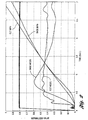
- Figure 2 demonstrates that the initial acceleration of the vehicle using the converterless transmission of the invention rises quickly immediately following the start of a launch, as indicated at 72.
- a corresponding acceleration plot for a known transmission for the same vehicle is shown at 74, the known transmission being of the type shown in U.S. Patent 4,938,097.
- the plot 74 rises with a lesser slope than the slope of the plot 72. This is due to the relatively large mass that creates an initial inertia during startup. Acceleration of that mass, which consists of the mass of the converter and the mass of the converter fluid, requires engine torque, thereby reducing the net torque that is available at the traction wheels immediately following the opening of the engine throttle by the operator.
- the reduced rotary mass for the converterless transmission of the invention compensates for the loss of the torque multiplication associated with a torque converter transmission of the kind shown, for example, in U.S. Patent 4,938,097.
- acceleration plot 74 will reach a higher peak compared to the peak acceleration of the transmission of the invention because of the torque multiplication of the converter, the peak occurs substantially later following the initial launch.
- the vehicle speed for a driveline having a transmission of the kind shown in U.S. Patent 4,938,097 is shown at 76.
- the corresponding vehicle speed versus time relationship for the converterless transmission of the invention is shown at 78.
- the plots 76 and 78, as observed in Figure 2, are not substantially different, one with respect to the other.
- the vehicle speeds are the same for each driveline.
- the converterless transmission driveline results in a higher vehicle speed, as shown in the right-hand portion of the plots of Figure 2. This is due in large measure to the improved operating efficiency of a converterless transmission compared to the corresponding torque converter transmission for which the converter efficiency is only about 80-85% due to hydrokinetic power losses.
- Figure 3 demonstrates the effect of the significant decrease in the inertia torque for the converterless transmission of the invention compared to a transmission of the kind shown in U.S. Patent 4,938,097.
- a plot of the inertia torque (I ⁇ ) for the base transmission is shown at 80, and the corresponding inertia torque relationship with respect to launch time for the converterless transmission of the invention is shown at 82.
- the hydrokinetic converter provides a smooth disconnect between the engine and the transmission.
- the disconnect is accomplished by a neutral idle-type control on the forward or reverse clutches 60 and 58, respectively.
- Torsional isolation can be accomplished to compensate for the torsional isolation normally provided by the converter in a base transmission. This is done by slipping a friction element by an incremental amount (e.g., 10-20 rpm) during torque delivery. If the transmission is operating in the first or second gear ratio, the slipping element is the forward clutch 60. In third ratio, either the forward clutch 60 or the direct clutch 58 can be controlled to effect the necessary slipping to achieve torsional isolation. During operation in the fourth ratio, the direct clutch 58 is controlled to achieve slipping. During reverse drive, the reverse clutch 56 is controlled to achieve slipping.
- Figure 4 shows a control valve system for obtaining the necessary torsional isolation and the necessary engine disconnect for the converterless transmission of the invention.
- the control valve circuit of Figure 4 includes five variable force solenoid valves. These are the low-and-reverse variable force solenoid valve 82, the 2/4 variable force solenoid valve 84, the direct-drive variable force solenoid valve 86, the forward-and-reverse variable force solenoid valve 88, and the electronic pressure control variable force solenoid 90.
- the transmission includes an engine-driven, positive-displacement transmission pump 92, which supplies line pressure through passage 94 to a driver-operated manual valve 96.
- the pressure in passage 94 is regulated by a main regulator valve 98 to produce a regulated line pressure in passage 94.
- a pressure feedback land 100 on the main regulator valve 98 opposes the force of regulator valve spring 102 to produce a controlled pressure in line pressure passage 94.
- Electronic pressure control variable force solenoid valve 90 receives line pressure from passage 94 and modulates it to produce an effective throttle valve pressure, or TV pressure, in passage 104.
- This throttle valve pressure is distributed to one end of the main regulator valve to supplement the force of the spring 102, thereby providing a variable pressure in line pressure passage 94, which is variable depending on the torque demand.
- the low-and-reverse variable force solenoid valve 82 is commanded by the vehicle transmission controller to produce a minimum pressure in passage 106, which is distributed to a startup shuttle valve 108.
- the shuttle valve 108 is a two-position valve, which is urged to the right by valve spring 110 and urged to the left by the pressure developed by the low-and-reverse variable force solenoid 82.
- the forward-and-reverse variable force solenoid valve 88 creates pressure for passage 112 as it modulates the pressure delivered to it from passage 120.
- This passage 120 is pressurized by reason of the connection provided by the forward-and-reverse shuttle valve 116 with the passage 118.
- Passage 118 is pressurized by the manual valve when the manual valve is positioned for drive range position D, the second ratio position 2 and the first ratio position 1.
- passage 118 becomes exhausted through the manual valve and reverse line pressure passage 122 becomes pressurized. This shifts the forward-and-reverse shuttle valve 116 to the left, thereby causing forward and reverse pressure in passage 114 to be distributed to the reverse clutch 56.
- the shuttle valve 124 and the priority 1 valve 126 prevent a transmission tie-up caused by simultaneous engagement of the direct clutch 58 and the low-and-reverse clutch 68.
- the shuttle valve 124 will shift to the left, thereby pressurizing the left side of priority 1 valve 126.
- pressure is distributed to the priority 1 valve 126 to supplement the force of spring 130.
- the low-and-reverse clutch then will be exhausted through line 128 and through passage 132 to the exhaust port 134 in the priority 1 valve 126.
- a tie-up caused by simultaneous engagement of the forward clutch 60, the low-and-reverse clutch 68 and the 2/4 brake 70 is avoided by the 2/4 direct shuttle valve 124 and the priority 1 valve 126.
- the shuttle valve 124 will shift to the right so that 2/4 brake pressure will be distributed from passage 136 through the shuttle valve 124 to the left side of the priority 1 valve. This causes the priority 1 valve to shift to the right and to exhaust the low-and-reverse clutch through the valve 124 and through the exhaust port 134 in the priority 1 valve 126.
- a tie-up caused by the simultaneous engagement of the forward clutch 60, the direct clutch 58 and the 2/4 brake band 70 is avoided by the priority 2 valve 138, which generally is similar in construction to the priority 1 valve 126.
- pressure in passage 140 and pressure in passage 142 act on the priority 2 valve 138 to establish pressure forces that act in combination with force of valve spring 144 to shift the priority 2 valve to the right.
- Pressure in passage 142 is obtained by the 2/4 variable force solenoid valve 84, which is supplied with line pressure through passage 146.
- Passage 136 which extends to the 2/4 brake band, then will be exhausted through exhaust port 148 in the priority 2 valve 138.
- the control valve system of Figure 4 includes an engine pitot tube pressure source generally identified by reference numeral 150.
- This includes a pitot tube element situated in a lube oil reservoir 152 driven by the engine. Relative motion of the fluid with respect to the pitot tube creates a pressure in passage 154, which is a function of the square of the engine speed. That pitot tube pressure acts on a pitot tube pressure regulator valve 156, which is supplied with line pressure from passage 120. Pressure in passage 120 is modulated by the valve 156 to produce a modulated pitot tube pressure in passage 158. This pressure is distributed to the passage 114 through the startup shuttle valve 108 when pressure is not available in passage 106 from the low-and-reverse variable force solenoid valve 82.
- shuttle valve 108 is shifted to the right under the influence of spring 110. This ensures that either the forward clutch 60 or the reverse clutch 58 will be pressurized through the forward and reverse shuttle valve 116. Thus, if there is an electrical failure that renders the variable force solenoid valves inoperable, a "limp home" capability is established.
- a loss of electric power for the variable force solenoid valves will cause the system to default to third gear when the manual valve is in the drive position. It will default to reverse gear if the manual valve is in the reverse position.
- a lubrication oil pressure regulator valve 160 acts in the usual fashion to establish a lubrication pressure in lube passage 162. It is supplied with pressure from the main regulator valve 98 in known fashion.
- Figure 6 shows in schematic form the neutral idle controller for the electronic damping.
- the controller maintains a small torque offset or delta torque as shown at 166. This is an offset from the average engine idle torque as the so-called set point torque (TQ_DES).
- TQ_DES set point torque
- the engagement control circuit of Figure 6 establishes closed-loop modulation of the engaging clutch pressure 168 with actual engine torque feedback.
- Engine torque which is obtained by a memory lookup table of the relationship between load and engine speed at 170, establishes a signal in signal flow path 172, which is equal to net torque (TQ_NET).
- TQ_NET net torque
- After being filtered by a low-pass filter circuit 174, the net torque is fed back to a summing point 176 as filtered torque TQ_NETF.
- An error signal is established if there is a difference between the values TQ_DES and TQ_NETF at the output side 178 of the summing point 176.
- the control for the clutch is achieved by a proportional-integral-differential controller 180.
- the output of the PID controller causes a change in the commanded pressure at location 182. This is the pressure T_TID.
- the circuit of Figure 5 which is a closed-loop circuit with actual engine speed as a feedback variable, becomes activated when the controller is signaled to launch the vehicle.
- the function of the circuit of Figure 5 takes over the engine idle controller in Figure 4 in a smooth fashion.
- An engine map or lookup table at 186 receives the throttle position signal from signal flow path 188.
- a vehicle speed signal received from signal flow path 190 together with the speed signal that is inferred from the memory lookup table 186, establishes a target speed for the engine in signal flow path 192. That signal is filtered at 194 to produce a desired engine speed signal at 196. That desired engine speed signal is compared to an actual engine speed signal in signal flow path 198. If there is a difference between these two engine speed signals, an error is indicated in signal flow path 200.
- the signal in signal flow path 198 is the actual feedback variable.
- a proportional-integral-derivative controller of conventional design receives the error signal, as shown at 202, resulting in a useful clutch pressure signal at 204 which is used to establish the desired clutch pressure.
- Figure 7 is a plot that shows a comparison of the desired torque (TQ_DES) with the actual torque TQ_NETF during the initial four seconds following a vehicle launch.
- the corresponding half-shaft torque also is shown at 188.
- the desired torque is shown at 190, and the actual torque is shown at 192.
- the actual torque approaches the desired torque level as the clutch pressure gradually increases, as shown by the curve 194.
- the engine speed remains relatively constant during this period, as shown at 196.
- Figure 8 shows simulated data for a converterless transmission of the invention indicating the speed variations and the torque variations that occur following engagement of the clutch.
- the effective engine speed variations and the corresponding input torque variations, which are relatively minor, are shown respectively at 198 and 200.
- the effective output half shaft torque is shown at 202.
Landscapes
- Engineering & Computer Science (AREA)
- General Engineering & Computer Science (AREA)
- Mechanical Engineering (AREA)
- Control Of Transmission Device (AREA)
- Structure Of Transmissions (AREA)
Claims (3)
- Drehmomentwandlerloses, mehrgängiges Automatikgetriebe für einen Kraftfahrzeug-Triebstrang mit einer Brennkraftmaschine (12), wobei das Getriebe (10) eine getriebene Welle im Drehmomentflußweg zu den Fahrzeugantriebsrädern (72) beinhaltet;
wobei Planetengetriebezüge (22, 23) des Getriebes mehrere Vorwärtsgang-Drehmomentübertragungswege zwischen dem Motor und der getriebenen Welle bilden;
wobei das Drehmomenteingangselement des Getriebes direkt so verbindbar ist, daß es von der Motorkurbelwelle (14) angetrieben wird, so daß die Motorkurbelwelle (14) und das Drehmomenteingangselement während der Drehmomentübertragung über die Drehmomentflußwege durchgehend so miteinander gekuppelt sind, daß sie sich gleichzeitig miteinander drehen;
druckbetätigte Reibungskupplungsmittel (56, 58, 60) im Getriebe zur Herstellung und Lösung der Drehmomentübertragungswege, einschließlich einer Vorwärtsgangkupplung (60), die zum Betrieb im Vorwärtsgang geschlossen wird; und
automatische Kupplungssteuerungsmittel zum Lösen und Einlegen der Vorwärtsgangkupplung (60) derart, daß der Motor jeweils mit dem Getriebe verbunden bzw. von dem Getriebe getrennt wird, so daß eine Steuerung des Triebstranges beim Anfahren des Fahrzeuges im Vorwärtsgang geschaffen wird;
dadurch gekennzeichnet, daß
die Kupplungssteuerungsmittel folgendes beinhalten:wobei der Prozessor Mittel (176) zur Erfassung des Motor-Ist-Parameters beim Anfahren des Fahrzeuges im Vorwärtsgang beinhaltet, und zum Vergleichen desselben mit einem durch einen Fahrzeugführer bestimmten Motor-Ziel-Parameter zwecks Erfassung einer Abweichung und Erstellung eines Vorwärtsgangkupplungsdruckes, der funktional in Relation zur Höhe dieser Abweichung steht.eine Leitungsdruckpumpe, welche mit dem Drehmomenteingangselement des Getriebes verbunden ist; undSteuerventilkreismittel, welche einen elektronischen Prozessor und ein von Hand betätigbares Gangbereichswahlventil beinhalten, über welches von der Leitungsdruckpumpe (92) erzeugter Druck in einem geschlossenen Regelkreis mit einem Ist-Parameter des Motors, der unter Motordrehzahl und Drehmoment als Rückkopplungsvariable ausgewählt wird, an die Vorwärtsgangkupplung (60) geleitet wird, so daß der Vorwärtskupplungsdruck ein kontrolliertes und sanftes Einlegen beim Anfahren des Fahrzeuges bewirkt; - Automatikgetriebe nach Anspruch 1, worin die Planetengetriebezüge des Getriebes außerdem einen Rückwärtsgang-Drehmomentflußweg zwischen dem Motor (12) und der getriebenen Welle bilden; und worin die automatischen Kupplungssteuerungsmittel die Steuerung des Triebstranges beim Anfahren des Fahrzeuges im Rückwärtsgang realisieren.
- Automatikgetriebe nach Anspruch 1 oder 2, worin der Steuerventilkreis elektromagnetisch betätigte Ventilmittel (90) aufweist, welche zur Herstellung eines kontrollierten Druckes, der an die Kupplungsmittel im Getriebe geleitet wird, mit der Leitungsdruckpumpe (92) kommunizieren; und
eine Hilfsdruckquelle (150) mit einem Staurohrdruckelement und einem vom Motor angetriebenen rotierenden Flüssigkeitstank (152), welcher Flüssigkeit enthält und mit dem Staudruckrohrelement in Eingriff steht; und
Mittel (108) zur Herstellung einer kontrollierten Verbindung zwischen der Hilfsdruckquelle und den Kupplungsmitteln im Getriebe, wenn die elektromagnetisch betätigten Ventilmittel ausgeschaltet bzw. ausgefallen ist.
Applications Claiming Priority (2)
| Application Number | Priority Date | Filing Date | Title |
|---|---|---|---|
| US09/353,289 US6217479B1 (en) | 1999-07-15 | 1999-07-15 | Converterless multiple-ratio automatic transmission |
| US353289 | 1999-07-15 |
Publications (3)
| Publication Number | Publication Date |
|---|---|
| EP1069349A2 EP1069349A2 (de) | 2001-01-17 |
| EP1069349A3 EP1069349A3 (de) | 2003-09-17 |
| EP1069349B1 true EP1069349B1 (de) | 2005-11-09 |
Family
ID=23388491
Family Applications (1)
| Application Number | Title | Priority Date | Filing Date |
|---|---|---|---|
| EP00305909A Expired - Lifetime EP1069349B1 (de) | 1999-07-15 | 2000-07-12 | Mehrgängiges, automatisches Getriebe ohne Drehmomentwandler |
Country Status (3)
| Country | Link |
|---|---|
| US (1) | US6217479B1 (de) |
| EP (1) | EP1069349B1 (de) |
| DE (1) | DE60023799T2 (de) |
Families Citing this family (35)
| Publication number | Priority date | Publication date | Assignee | Title |
|---|---|---|---|---|
| JP3797041B2 (ja) * | 1999-10-08 | 2006-07-12 | トヨタ自動車株式会社 | 自動変速機の油圧制御装置 |
| JP3327262B2 (ja) * | 1999-10-08 | 2002-09-24 | トヨタ自動車株式会社 | 車両の後進走行装置 |
| US7407026B2 (en) * | 2000-10-11 | 2008-08-05 | Ford Global Technologies, Llc | Control system for a hybrid electric vehicle to anticipate the need for a mode change |
| GB2370130B (en) * | 2000-10-11 | 2004-10-06 | Ford Motor Co | A control system for a hybrid electric vehicle |
| US6827664B2 (en) * | 2001-11-15 | 2004-12-07 | General Motors Corporation | Transmission |
| US6842673B2 (en) * | 2002-06-05 | 2005-01-11 | Visteon Global Technologies, Inc. | Engine engagement control for a hybrid electric vehicle |
| US6868949B2 (en) * | 2003-02-06 | 2005-03-22 | Borgwarner, Inc. | Start-up clutch assembly |
| US20040179962A1 (en) * | 2003-03-12 | 2004-09-16 | Hopper Mark L. | System and method for regulating pressure in an automatic transmission |
| US6926639B2 (en) | 2003-07-02 | 2005-08-09 | Visteon Global Technologies, Inc. | Vehicle control method |
| US6974402B2 (en) * | 2004-02-17 | 2005-12-13 | Ford Global Technologies, Llc | Launch control of hybrid electric vehicle having a torque converterless driveline |
| DE502004002172D1 (de) * | 2004-04-10 | 2007-01-11 | Borgwarner Inc | Kupplungseinrichtung, insbesondere Anfahrkupplungseinrichtung |
| DE102004030660A1 (de) | 2004-06-24 | 2006-01-26 | Borgwarner Inc., Auburn Hills | Kupplung |
| DE502004006495D1 (de) * | 2004-06-29 | 2008-04-24 | Borgwarner Inc | Mehrfachkupplungsanordnung |
| US7326149B2 (en) * | 2004-11-05 | 2008-02-05 | Ford Global Technologies, Llc | Converterless transmission shift control system |
| DE102006042353A1 (de) * | 2006-09-08 | 2008-03-27 | Zf Friedrichshafen Ag | Verfahren zum Realisieren eines Kriech-Modus bei einem Fahrzeug, umfassend ein Getriebe mit einer Anfahrkupplung |
| US8138703B2 (en) * | 2007-11-04 | 2012-03-20 | GM Global Technology Operations LLC | Method and apparatus for constraining output torque in a hybrid powertrain system |
| US8793002B2 (en) * | 2008-06-20 | 2014-07-29 | Caterpillar Inc. | Torque load control system and method |
| US7795752B2 (en) | 2007-11-30 | 2010-09-14 | Caterpillar Inc | System and method for integrated power control |
| US7998026B2 (en) * | 2008-01-17 | 2011-08-16 | Ford Global Technologies, Llc | Vehicle launch using a transmission input clutch |
| CN101946105B (zh) | 2008-03-04 | 2013-07-17 | 博格华纳公司 | 具有区域控制的离合器冷却回路的双离合器变速器 |
| WO2009128806A1 (en) | 2008-04-18 | 2009-10-22 | Borgwarner Inc. | Dual clutch transmission having simplified controls |
| US8607745B2 (en) * | 2008-10-31 | 2013-12-17 | Borgwarner Inc. | Electro-hydraulic pressure control fan drive system with electrical failure mode operation |
| US8058829B2 (en) | 2008-11-25 | 2011-11-15 | Caterpillar Inc. | Machine control system and method |
| WO2010077560A2 (en) * | 2008-12-09 | 2010-07-08 | Borgwarner Inc. | Automatic transmission for a hybrid vehicle |
| JP4913170B2 (ja) * | 2009-02-12 | 2012-04-11 | ジヤトコ株式会社 | 自動変速機の油圧制御装置 |
| US9086170B2 (en) | 2009-06-29 | 2015-07-21 | Borgwarner Inc. | Hydraulic valve for use in a control module of an automatic transmission |
| US8826760B2 (en) | 2009-12-31 | 2014-09-09 | Borgwarner Inc. | Automatic transmission having high pressure actuation and low pressure lube hydraulic circuit |
| US8814741B2 (en) * | 2011-02-04 | 2014-08-26 | Fuji Jukogyo Kabushiki Kaisha | Drive device for vehicle |
| US8540048B2 (en) | 2011-12-28 | 2013-09-24 | Caterpillar Inc. | System and method for controlling transmission based on variable pressure limit |
| US9067593B2 (en) | 2013-03-08 | 2015-06-30 | Toyota Motor Engineering & Manufacturing North America, Inc. | Hybrid vehicle launch control |
| US9802602B2 (en) * | 2016-01-08 | 2017-10-31 | Ford Global Technologies, Llc | Methods and system for mitigating engine and motor torque disturbances of a hybrid vehicle |
| US10612650B2 (en) | 2016-02-22 | 2020-04-07 | Deere & Company | Double disconnect transmission reverser with disconnect synchronizer |
| US10330191B2 (en) * | 2016-02-22 | 2019-06-25 | Deere & Company | Double disconnect transmission reverser with disconnect synchronizer |
| DE102016215562A1 (de) * | 2016-08-19 | 2018-02-22 | Zf Friedrichshafen Ag | Getriebe für ein Kraftfahrzeug, sowie Hybridantriebsstrang |
| CN112394755B (zh) * | 2020-11-03 | 2022-03-15 | 武汉格罗夫氢能汽车有限公司 | 一种氢燃料电池车的怠速扭矩匹配方法 |
Family Cites Families (20)
| Publication number | Priority date | Publication date | Assignee | Title |
|---|---|---|---|---|
| US3319491A (en) | 1963-12-24 | 1967-05-16 | Howard W Simpson | Heavy duty planetary transmission |
| JPS4820348B1 (de) * | 1968-10-30 | 1973-06-20 | ||
| CA1049293A (en) | 1974-07-01 | 1979-02-27 | Borg-Warner Corporation | Automatic transmission |
| US4433594A (en) | 1981-04-24 | 1984-02-28 | Borg-Warner Corporation | Variable pulley transmission |
| DE3202692C2 (de) | 1982-01-28 | 1986-03-27 | Ford-Werke AG, 5000 Köln | Stufenlos regelbares Getriebeaggregat für Kraftfahrzeuge |
| WO1985001332A1 (fr) | 1983-09-15 | 1985-03-28 | Zahnradfabrik Friedrichshafen Ag | Accouplement a lamelles |
| JPS60174332A (ja) | 1984-02-16 | 1985-09-07 | Diesel Kiki Co Ltd | 車輛用自動変速装置 |
| US4602525A (en) | 1984-04-27 | 1986-07-29 | Aisin Warner Kabushiki Kaisha | Continuously variable speed transmission for a vehicle having a forward-reverse changeover mechanism |
| US4683776A (en) * | 1986-02-27 | 1987-08-04 | General Motors Corporation | Transmission gearing arrangement |
| US4873637A (en) * | 1988-02-10 | 1989-10-10 | Eaton Corporation | Control for vehicle start from stop operation |
| US4938097A (en) | 1989-04-11 | 1990-07-03 | Ford Motor Company | Four speed transaxle for automotive vehicles |
| JP3572623B2 (ja) | 1992-08-31 | 2004-10-06 | 本田技研工業株式会社 | 車両用クラッチの制御装置 |
| US5389046A (en) | 1993-05-25 | 1995-02-14 | Ford Motor Company | Automatic transmission control system |
| JP2830970B2 (ja) * | 1994-02-17 | 1998-12-02 | 本田技研工業株式会社 | クラッチの制御装置 |
| JP3237419B2 (ja) | 1994-10-21 | 2001-12-10 | トヨタ自動車株式会社 | 車両用クラッチ制御装置 |
| JP3456329B2 (ja) | 1995-12-08 | 2003-10-14 | アイシン・エィ・ダブリュ株式会社 | 車両用駆動装置の制御装置 |
| DE19546707A1 (de) | 1995-12-14 | 1997-06-19 | Bayerische Motoren Werke Ag | Antriebseinrichtung für ein Kraftfahrzeug |
| JP3221311B2 (ja) * | 1996-02-29 | 2001-10-22 | トヨタ自動車株式会社 | 自動変速機の制御装置 |
| JP3955369B2 (ja) * | 1997-10-23 | 2007-08-08 | 富士重工業株式会社 | 自動変速装置 |
| US6176808B1 (en) * | 1999-07-15 | 2001-01-23 | Ford Global Technologies, Inc. | Hybrid vehicle powertrain and control therefor |
-
1999
- 1999-07-15 US US09/353,289 patent/US6217479B1/en not_active Expired - Fee Related
-
2000
- 2000-07-12 DE DE60023799T patent/DE60023799T2/de not_active Expired - Fee Related
- 2000-07-12 EP EP00305909A patent/EP1069349B1/de not_active Expired - Lifetime
Also Published As
| Publication number | Publication date |
|---|---|
| US6217479B1 (en) | 2001-04-17 |
| DE60023799D1 (de) | 2005-12-15 |
| EP1069349A2 (de) | 2001-01-17 |
| EP1069349A3 (de) | 2003-09-17 |
| DE60023799T2 (de) | 2006-06-22 |
Similar Documents
| Publication | Publication Date | Title |
|---|---|---|
| EP1069349B1 (de) | Mehrgängiges, automatisches Getriebe ohne Drehmomentwandler | |
| EP1068977B1 (de) | Getriebe und Steuerungssystem für einen Verbrennungsmotor in einem Hybridfahrzeug | |
| EP0308072B1 (de) | Überbrückungs- und Schaltkupplungsanordnung für einen Drehmomentwandler | |
| US4757886A (en) | Transmission clutch closed loop slip controller and method | |
| US5036729A (en) | Coast-sync-coast downshift control method for clutch-to-clutch transmission shifting | |
| EP1101969B1 (de) | Steuerungsstrategie für ein automatisches Getriebe | |
| US4637281A (en) | Control valve system for a four-speed automatic power transmission transaxle | |
| EP0235892A1 (de) | Herunterschalten unter Last von Kupplung zu Kupplung in einem automatischen Getriebe eines Kraftfahrzeugs | |
| US4827805A (en) | Forward and reverse clutch actuation system for a belt-driven continually variable transmission | |
| US5389046A (en) | Automatic transmission control system | |
| JPH06201026A (ja) | 自動変速機の油圧制御装置 | |
| JPH0633816B2 (ja) | 自動変速機のトルク確立装置の作動方法 | |
| EP0274079B1 (de) | Steuerungssysteme für die Überbrückungskupplung eines Momentwandlers eines automatischen Getriebes | |
| US4665770A (en) | Control system for a multiple ratio transmission having a lockup clutch torque converter | |
| JPH04262167A (ja) | 変速機の作動方法 | |
| EP0210485A2 (de) | Steuerventilsystem für ein automatisches Vierganggetriebe mit einem Zweibereich-Regulierventil zum unabhängigen Steuern zweier Hinauf-Schaltvorgänge | |
| EP0626529B1 (de) | Kraftfahrzeuggetriebe | |
| US5315901A (en) | Automatic transmission with a modulated pressure converter bypass clutch priority valve circuit | |
| US4747808A (en) | System for actuating the displaceable pulley in a continually variable transmission | |
| US6171211B1 (en) | Automatic transmission control system having a neutral idle feature | |
| JP2004291908A (ja) | 自動変速機の制御装置および制御方法 | |
| US5902213A (en) | Shift control device for automatic transmission | |
| EP0405082A1 (de) | Steuerungssystem für ein automatisches Getriebe und dessen Arbeitsweise | |
| EP0195295B1 (de) | Steuersystem für ein mehrgängiges Getriebe mit sperrbarem Drehmomentwandler | |
| US4841813A (en) | Oil pressure circuit for an automatic transmission |
Legal Events
| Date | Code | Title | Description |
|---|---|---|---|
| PUAI | Public reference made under article 153(3) epc to a published international application that has entered the european phase |
Free format text: ORIGINAL CODE: 0009012 |
|
| AK | Designated contracting states |
Kind code of ref document: A2 Designated state(s): AT BE CH CY DE DK ES FI FR GB GR IE IT LI LU MC NL PT SE |
|
| AX | Request for extension of the european patent |
Free format text: AL;LT;LV;MK;RO;SI |
|
| PUAL | Search report despatched |
Free format text: ORIGINAL CODE: 0009013 |
|
| RAP1 | Party data changed (applicant data changed or rights of an application transferred) |
Owner name: LAWRENCE TECHNOLOGICAL UNIVERSITY |
|
| AK | Designated contracting states |
Kind code of ref document: A3 Designated state(s): AT BE CH CY DE DK ES FI FR GB GR IE IT LI LU MC NL PT SE |
|
| AX | Request for extension of the european patent |
Extension state: AL LT LV MK RO SI |
|
| RIC1 | Information provided on ipc code assigned before grant |
Ipc: 7F 16D 48/08 B Ipc: 7F 16H 3/12 B Ipc: 7F 16H 3/66 B Ipc: 7F 16H 61/02 A |
|
| 17P | Request for examination filed |
Effective date: 20040303 |
|
| AKX | Designation fees paid |
Designated state(s): DE FR GB |
|
| 17Q | First examination report despatched |
Effective date: 20040504 |
|
| GRAP | Despatch of communication of intention to grant a patent |
Free format text: ORIGINAL CODE: EPIDOSNIGR1 |
|
| GRAS | Grant fee paid |
Free format text: ORIGINAL CODE: EPIDOSNIGR3 |
|
| GRAA | (expected) grant |
Free format text: ORIGINAL CODE: 0009210 |
|
| AK | Designated contracting states |
Kind code of ref document: B1 Designated state(s): DE FR GB |
|
| REG | Reference to a national code |
Ref country code: GB Ref legal event code: FG4D |
|
| REF | Corresponds to: |
Ref document number: 60023799 Country of ref document: DE Date of ref document: 20051215 Kind code of ref document: P |
|
| ET | Fr: translation filed | ||
| PGFP | Annual fee paid to national office [announced via postgrant information from national office to epo] |
Ref country code: FR Payment date: 20060714 Year of fee payment: 7 Ref country code: DE Payment date: 20060714 Year of fee payment: 7 |
|
| PGFP | Annual fee paid to national office [announced via postgrant information from national office to epo] |
Ref country code: GB Payment date: 20060720 Year of fee payment: 7 |
|
| PLBE | No opposition filed within time limit |
Free format text: ORIGINAL CODE: 0009261 |
|
| STAA | Information on the status of an ep patent application or granted ep patent |
Free format text: STATUS: NO OPPOSITION FILED WITHIN TIME LIMIT |
|
| 26N | No opposition filed |
Effective date: 20060810 |
|
| GBPC | Gb: european patent ceased through non-payment of renewal fee |
Effective date: 20070712 |
|
| PG25 | Lapsed in a contracting state [announced via postgrant information from national office to epo] |
Ref country code: DE Free format text: LAPSE BECAUSE OF NON-PAYMENT OF DUE FEES Effective date: 20080201 |
|
| PG25 | Lapsed in a contracting state [announced via postgrant information from national office to epo] |
Ref country code: GB Free format text: LAPSE BECAUSE OF NON-PAYMENT OF DUE FEES Effective date: 20070712 |
|
| REG | Reference to a national code |
Ref country code: FR Ref legal event code: ST Effective date: 20080331 |
|
| PG25 | Lapsed in a contracting state [announced via postgrant information from national office to epo] |
Ref country code: FR Free format text: LAPSE BECAUSE OF NON-PAYMENT OF DUE FEES Effective date: 20070731 |