EP1069315A2 - Turbomaschinen - Google Patents
Turbomaschinen Download PDFInfo
- Publication number
- EP1069315A2 EP1069315A2 EP00114868A EP00114868A EP1069315A2 EP 1069315 A2 EP1069315 A2 EP 1069315A2 EP 00114868 A EP00114868 A EP 00114868A EP 00114868 A EP00114868 A EP 00114868A EP 1069315 A2 EP1069315 A2 EP 1069315A2
- Authority
- EP
- European Patent Office
- Prior art keywords
- impeller
- grooves
- casing
- pump
- blades
- Prior art date
- Legal status (The legal status is an assumption and is not a legal conclusion. Google has not performed a legal analysis and makes no representation as to the accuracy of the status listed.)
- Granted
Links
- 239000012530 fluid Substances 0.000 claims description 52
- 230000003068 static effect Effects 0.000 claims description 13
- 238000011144 upstream manufacturing Methods 0.000 claims description 11
- 230000009467 reduction Effects 0.000 claims description 10
- 230000002093 peripheral effect Effects 0.000 claims description 7
- 238000007789 sealing Methods 0.000 claims description 7
- 230000008878 coupling Effects 0.000 claims description 6
- 238000010168 coupling process Methods 0.000 claims description 6
- 238000005859 coupling reaction Methods 0.000 claims description 6
- 238000005086 pumping Methods 0.000 claims description 2
- 230000003247 decreasing effect Effects 0.000 description 22
- 230000000694 effects Effects 0.000 description 13
- 238000003754 machining Methods 0.000 description 11
- 238000011282 treatment Methods 0.000 description 11
- XLYOFNOQVPJJNP-UHFFFAOYSA-N water Substances O XLYOFNOQVPJJNP-UHFFFAOYSA-N 0.000 description 9
- 239000007788 liquid Substances 0.000 description 6
- 238000010276 construction Methods 0.000 description 5
- 230000006872 improvement Effects 0.000 description 5
- 238000005520 cutting process Methods 0.000 description 4
- 238000000034 method Methods 0.000 description 4
- 230000008901 benefit Effects 0.000 description 2
- 230000008859 change Effects 0.000 description 2
- 238000010586 diagram Methods 0.000 description 2
- 238000004519 manufacturing process Methods 0.000 description 2
- 230000001151 other effect Effects 0.000 description 2
- 230000007547 defect Effects 0.000 description 1
- 238000007598 dipping method Methods 0.000 description 1
- 230000009191 jumping Effects 0.000 description 1
- 230000007246 mechanism Effects 0.000 description 1
- 230000006641 stabilisation Effects 0.000 description 1
- 238000011105 stabilization Methods 0.000 description 1
Images


Classifications
-
- F—MECHANICAL ENGINEERING; LIGHTING; HEATING; WEAPONS; BLASTING
- F04—POSITIVE - DISPLACEMENT MACHINES FOR LIQUIDS; PUMPS FOR LIQUIDS OR ELASTIC FLUIDS
- F04D—NON-POSITIVE-DISPLACEMENT PUMPS
- F04D29/00—Details, component parts, or accessories
- F04D29/66—Combating cavitation, whirls, noise, vibration or the like; Balancing
- F04D29/68—Combating cavitation, whirls, noise, vibration or the like; Balancing by influencing boundary layers
- F04D29/688—Combating cavitation, whirls, noise, vibration or the like; Balancing by influencing boundary layers especially adapted for liquid pumps
-
- F—MECHANICAL ENGINEERING; LIGHTING; HEATING; WEAPONS; BLASTING
- F04—POSITIVE - DISPLACEMENT MACHINES FOR LIQUIDS; PUMPS FOR LIQUIDS OR ELASTIC FLUIDS
- F04D—NON-POSITIVE-DISPLACEMENT PUMPS
- F04D27/00—Control, e.g. regulation, of pumps, pumping installations or pumping systems specially adapted for elastic fluids
- F04D27/009—Control, e.g. regulation, of pumps, pumping installations or pumping systems specially adapted for elastic fluids by bleeding, by passing or recycling fluid
-
- F—MECHANICAL ENGINEERING; LIGHTING; HEATING; WEAPONS; BLASTING
- F04—POSITIVE - DISPLACEMENT MACHINES FOR LIQUIDS; PUMPS FOR LIQUIDS OR ELASTIC FLUIDS
- F04D—NON-POSITIVE-DISPLACEMENT PUMPS
- F04D29/00—Details, component parts, or accessories
- F04D29/40—Casings; Connections of working fluid
- F04D29/42—Casings; Connections of working fluid for radial or helico-centrifugal pumps
- F04D29/4206—Casings; Connections of working fluid for radial or helico-centrifugal pumps especially adapted for elastic fluid pumps
- F04D29/4213—Casings; Connections of working fluid for radial or helico-centrifugal pumps especially adapted for elastic fluid pumps suction ports
-
- F—MECHANICAL ENGINEERING; LIGHTING; HEATING; WEAPONS; BLASTING
- F04—POSITIVE - DISPLACEMENT MACHINES FOR LIQUIDS; PUMPS FOR LIQUIDS OR ELASTIC FLUIDS
- F04D—NON-POSITIVE-DISPLACEMENT PUMPS
- F04D29/00—Details, component parts, or accessories
- F04D29/40—Casings; Connections of working fluid
- F04D29/42—Casings; Connections of working fluid for radial or helico-centrifugal pumps
- F04D29/426—Casings; Connections of working fluid for radial or helico-centrifugal pumps especially adapted for liquid pumps
- F04D29/4273—Casings; Connections of working fluid for radial or helico-centrifugal pumps especially adapted for liquid pumps suction eyes
-
- F—MECHANICAL ENGINEERING; LIGHTING; HEATING; WEAPONS; BLASTING
- F04—POSITIVE - DISPLACEMENT MACHINES FOR LIQUIDS; PUMPS FOR LIQUIDS OR ELASTIC FLUIDS
- F04D—NON-POSITIVE-DISPLACEMENT PUMPS
- F04D29/00—Details, component parts, or accessories
- F04D29/66—Combating cavitation, whirls, noise, vibration or the like; Balancing
- F04D29/669—Combating cavitation, whirls, noise, vibration or the like; Balancing especially adapted for liquid pumps
-
- F—MECHANICAL ENGINEERING; LIGHTING; HEATING; WEAPONS; BLASTING
- F04—POSITIVE - DISPLACEMENT MACHINES FOR LIQUIDS; PUMPS FOR LIQUIDS OR ELASTIC FLUIDS
- F04D—NON-POSITIVE-DISPLACEMENT PUMPS
- F04D29/00—Details, component parts, or accessories
- F04D29/66—Combating cavitation, whirls, noise, vibration or the like; Balancing
- F04D29/68—Combating cavitation, whirls, noise, vibration or the like; Balancing by influencing boundary layers
- F04D29/681—Combating cavitation, whirls, noise, vibration or the like; Balancing by influencing boundary layers especially adapted for elastic fluid pumps
- F04D29/685—Inducing localised fluid recirculation in the stator-rotor interface
-
- F—MECHANICAL ENGINEERING; LIGHTING; HEATING; WEAPONS; BLASTING
- F05—INDEXING SCHEMES RELATING TO ENGINES OR PUMPS IN VARIOUS SUBCLASSES OF CLASSES F01-F04
- F05B—INDEXING SCHEME RELATING TO WIND, SPRING, WEIGHT, INERTIA OR LIKE MOTORS, TO MACHINES OR ENGINES FOR LIQUIDS COVERED BY SUBCLASSES F03B, F03D AND F03G
- F05B2260/00—Function
- F05B2260/96—Preventing, counteracting or reducing vibration or noise
Definitions
- the present invention relates to turbo machines, and in particular relates to a turbo machine being able to prevent from instability in flow, by suppressing swirl due to recirculation flow at an inlet of an impeller and by suppressing rotation stalls of the impeller, irrespective of the types and the fluid thereof.
- the present invention relates to the turbo machines, such as for a pump, a compressor, a blower, etc., having non-volume type impeller therewith, and in particular, relates to the turbo machine being able to prevent from the instability in flow, by suppressing a swirl or pre-whirl which is generated due to a main flow or component of the recirculation occurring at an inlet of an impeller and by suppressing rotation stalls thereof, thereby being suitable to be applied into a mixed-flow pump, which is used widely as water circulating pumps in a thermal power plant or in a nuclear power plant, a drainage pump, as well as, relates to a pump station into which is applied the turbo machine according to the present invention.
- a mixed-flow pump which is used widely as water circulating pumps in a thermal power plant or in a nuclear power plant, a drainage pump, as well as, relates to a pump station into which is applied the turbo machine according to the present invention.
- Rotary machines being called by a name of "turbo machine” can be classified as below, depending upon the fluids by which the machines are operated and in types thereof.
- An axial flow type, a mixed-flow type, and a centrifugal type An axial flow type, a mixed-flow type, and a centrifugal type.
- Fig. 22 showing a cross-section view of a mixed-flow pump which is now mainly or widely used due to easiness in operation thereof, it comprises a suction casing 11, a pump 12 and a diffuser 13, in a sequence from upper stream to down stream thereof.
- a blade (of an impeller) 122 rotating within a casing 121 of the pump 12 is rotationally driven on a rotary shaft 123, thereby supplying energy to the liquid which is suctioned from the suction casing 11.
- the diffuser 13 has a function of converting a portion of velocity (or kinetic) energy of the liquid into static pressure.
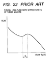
- Fig. 23 shows a typical characteristic curve between head and flow rate of the turbo machine including the mixed flow pump shown in Fig. 22, where the horizontal axis shows a parameter indicating the flow rate, while the vertical axis a parameter indicating the head.
- the head falls down in reverse relation to increase of the flow rate in a region of low flow rate, however it rises up following the increase of the flow rate during the time when the flow rate lies within a S region (i.e., a portion uprising or jumping up at the right-hand side in the characteristic curve). And, when the flow rate rises up further, exceeding over the right-hand uprising portion of the characteristic curve, the head begins to fall down, again, following the increase in the flow rate.
- the surging gives damages not only upon the turbo machine, but also upon conduits or pipes which are connected to upper stream and down stream sides thereof, it is inhibited to be practiced in a region of low flow rate. Further, there were already proposed various methods for suppressing the surging as below, other than an improvement made in the shape (i.e., profile) of the blade, for the purpose of expanding or enlarging the operation region of the turbo machine.
- Thin or narrow grooves or drains being from 10% to 20% of a chordal length of the blade, are formed in a casing region where the impeller lies, so as to improve a stall margin.
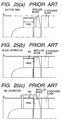
- Figs. 24 (a) and (b) show explanatory views of the casing treatment which were already proposed, in particular, Fig. 24 (a) shows a positional relationship between the casing treatment and the blades, and Fig. 24 (b) shows the cross section views of the casing treatment.
- the grooves being sufficient in the depth are formed in an inner wall (i.e., flow surface) of the casing on the region where the blades lie, in an axial direction, in a peripheral direction, or in an oblique direction, alternatively, in a radial direction or an oblique direction, respectively.
- a separator is provided for dividing the recirculation flow occurring at the outer edge of the inlet of the impeller into a reverse flow portion and a forward flow portion (i.e., in a main flow direction), in the region of low flow rate, thereby prohibiting the expansion of the recirculation.
- Figs. 25 (a) - (c) are explanatory views for the separators, each of which is applied to the turbo machine of the axial flow type, in particular, there are proposed a suction ring type (in Fig. 25 (a)), a blade separator type (in Fig. 25 (b)), and an air separator type (in Fig. 25 (c)), respectively.
- the reverse flow is enclosed within an outside of the suction ring, and in the blade separator type (in Fig. 25 (b)) is provided a fin between the casing and the ring. Further, with the air separator type (in Fig. 25 (c)), a front end or a tip of the moving wing (i.e., the blade) is opened so as to introduce the reverse flows into the outside of the casing, thereby prohibiting the swirl from being generated due to the reverse flows by means of the fin.
- the air separator type in Fig. 25 (c)
- a mixed-flow pump As an example of the conventional turbo machines, a mixed-flow pump will be described hereinafter.
- head curve head-flow rate characteristic curve
- the characteristics such as an efficiency representing performance of the pump, a stability of the head curve, a cavitation performance, and an axial motive power for closure, etc., are in reversed relationships to one another.
- the head curve shows a remarkable behavior uprising at the right-hand side in a portion thereof, thereby it has a tendency to be unstable.
- the turbo machine is decreased down by approximately 1 % in the efficiency thereof, if it rises up by an every 10 % in the stall margin, in accordance with the casing treatment.
- An object in accordance with the present invention is, for dissolving the drawbacks in the conventional art mentioned in the above, to provide a turbo machine, with which not only removing such the behavior uprising at the right-hand side from the characteristic curve between the head and the flow rate, but also being able to suppress the decrease in the efficiency, i.e., suppressing the swirl generated due to the recirculation occurring at the inlet of the impeller and the rotating stall of thereof.
- an object according to the present invention is to provide a turbo machine which has the head-flow rate characteristic curve without such the behavior of falling down at the right-hand side, as well as can also obtain high efficiency therewith.
- Another object according to the present invention is to provide a turbo machine, with which can be obtain such the head-flow rate characteristic curve without the behavior of falling down at the right-hand side, as well as can be manufactured with ease.
- object according to the present invention is to provide a turbo machine having the closed-type impeller, with which also can be obtain such the head-flow rate characteristic curve without such the behavior of falling down at the right-hand side.
- a turbo machine comprising:
- said impeller is an open-type impeller having a plurality of blades therewith, and a bottom surface of each of said grooves is so constructed that it is equal or higher than the flow surface of said casing being adjacent thereto in height thereof.
- said impeller is an open-type impeller having a plurality of blades therewith, and the flow surface of said casing being adjacent with a lower flow at a terminal end of each of said grooves is formed so that it is at same level of the bottom surface of each said groove or lies in a direction of an external diameter thereof, the outer periphery portion of said impeller at the inlet side of the blades thereof opposing to a groove portion is so constructed that it is low in height of the blade thereof corresponding to the groove portion, while the height of the each blade of said impeller in a lower flow side than said grooves is higher than that at the portion opposing to that of said groove portion.
- said impeller is an open-type impeller having a plurality of blades therewith, and a bottom surface of each said grooves is so constructed that it is equal or higher than the flow surface of said casing being adjacent thereto in a height thereof, as well as the outer periphery portion of said impeller at the inlet side of the blades thereof, opposing to a groove portion, is so constructed that it is low in height at the blades thereof corresponding to that groove portion.
- said impeller is an open-type impeller having a plurality of blades therewith, and height of each of the blades on a meridian plane in vicinity of an inlet of said impeller is made to be smaller than that on a meridian plane in vicinity of an outlet of said impeller, and those heights of the blades are determined corresponding to height of a groove portion.
- said impeller is an open-type impeller having a plurality of blades therewith, and further:
- said impeller is a closed-type impeller having a plurality of blades and a shroud thereabouts and said impeller is formed into an open-type having no shroud thereabouts in vicinity of an inlet of said impeller;
- said impeller is a closed-type impeller having a plurality of blades and a shroud thereabouts and said impeller is formed into an open-type having no shroud thereabouts in vicinity of an inlet of said impeller;
- the turbo machine as defined in the above further comprises an axis sealing portion for sealing between a minimum radial portion of the shroud of said impeller and said casing, wherein said axis sealing portion includes a mouth ring portion and a casing ring portion.
- a terminal position at downstream side of each of said grooves is located in such a manner that fluid can be obtained under pressure being necessary to suppress generation of the swirl in inlet main flow at a terminal position, at upstream side of each of said grooves, thereby removing a behavior of uprising at the right-hand side from a head-flow rate characteristic curve of said turbo machine;
- said casing is constructed with a plurality of casing liners, being divided in an axial direction thereof, and said grooves are formed on the inner surface of a casing liner opposing to the outer peripheral portion at the inlet side of the blades of said impeller.
- a pump station for lifting up a fluid head in a suction side up to that of a discharge side comprising:
- a rotation speed of said driver apparatus is controlled in a control range from 60% to 100% with respect to a reference rotation speed
- said driving apparatus for the pump comprises a speed reduction gear, a fluid coupling and a diesel engine.
- a rotation speed of said driver apparatus is controlled in a control range from 60% to 100% with respect to a reference rotation speed
- said driving apparatus for the pump comprises a speed reduction gear, a fluid coupling and a gas turbine.
- a rotation speed of said driver apparatus is controlled in a control range from 0% to 100% with respect to a reference rotation speed
- said driving apparatus for the pump comprises an electric motor for controlling the rotation speed by an inverter.
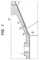
- Fig. 1 is an enlarged section view of a first embodiment of the present invention, for example, the mixed-flow pump shown in the Fig. 22, and in particular, an enlarged view of a portion which is enclosed by a one-dotted chain line in that Fig.
- a turbo machine according to the present invention with which a swirl due to the reverse flow at the blade inlet is suppressed, wherein shallow grooves 124 are formed on a flow surface of the casing 121 along with an inclination of pressure of the fluid (i.e., gradient of pressure), bridging over from a middle portion "a" (i.e., a terminal position of the groove at downstream side) of the blade 122 up to a position "b" (i.e., a terminal position of the groove at upper stream side) where the recirculation occurs in the low flow rate.
- a middle portion
- b i.e., a terminal position of the groove at upper stream side
- the fluid increased in pressure by the blade begins to flows into the reverse direction within the grooves 124, directing from the terminal position "a" at downstream side to the terminal position "b" at the upper stream side, and is injected or sprouted out into the place or spot where the recirculation occurs in the low flow rate, so as to prevent from occurrence of the swirl due to the recirculation, as well as the rotating stall of the impeller.
- Fig. 2 is an explanatory view for showing an effect of the present invention (a part 1), in particular, the effect by forming the grooves.
- the horizontal axis indicates the flow rate of fluid, while the vertical axis the head, both without dimensions thereof.
- white circles indicate the characteristic curve of the head-flow rate in a case where no groove is formed in the casing, wherein there still can be seen such a behavior that it upraises or jumps up at the right-hand side, following the increase in the flow rate within a range from 0.12 to 0.14 of the flow rate without dimension.
- the behavior uprising at the right-hand side cannot be dissolved or removed in the case where the grooves of the width and the depth 5 ⁇ 4 mm are formed, however it is completely dissolved in the case where the grooves of the width and the depth 10 ⁇ 2 mm are formed. Namely, it indicates that the shallow and wide grooves are more effective than those being deep in the depth, when forming thereof.
- the Fig. 2 also indicates that, though the efficiency ⁇ is decreased down due to the reverse flow of fluid within the channels theoretically, it is so small that it practically cannot be acknowledged.
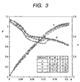
- Fig. 3 is an explanatory view for showing another effect of the present invention (a part 2), in particular showing influence of length of the grooves.
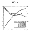
- Fig. 4 is an explanatory view for showing the other effect of the present invention (a part 3), in particular for showing influences of the depth and the width of the grooves.
- the depth does not give much influence upon the characteristic curve of the head-flow rate, however, the wider the width, the better the characteristic curve of the head-flow rate, i.e., the behavior uprising at the right-hand side is improved.
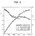
- Fig. 5 is an explanatory view for showing further other effect of the present invention (a part 4), in particular, also for showing influences of the depth and the width of the grooves.
- the grooves are kept to be same in the configuration or profile thereof, the more the number of pieces of the grooves, the better the characteristic curve of the head-flow rate, i.e., the behavior of uprising at the right-hand side is improved.
- turbo machine there are provided flow passages or channels for connecting between a spot at the inlet of the impeller where the recirculation occurs when the flow rate is low and an area on the flow surface of the casing in which the blades of the impeller reside in a gradient direction of fluid pressure, for the purpose of suppressing the swirl due to the recirculation at the inlet of the impeller, as well as the rotating stall thereof.
- the grooves are provided in the direction of main gradient of fluid pressure and the easiest configuration or shape thereof is in a straight line-like, with aligning a central line of the groove in the axial direction, however the grooves are provided on the inner wall (i.e., the flow surface) of the casing at the side opposing to the impeller, and are formed in the condition of being sunken from the casing wall.
- the shroud is removed only at the blade portion where the recirculation occurs in the inlet portion of the closed-type impeller, while it is remained in the downstream side thereof for remaining the impeller as that with the shroud thereabouts.
- the plurality of grooves are formed on a portion of the casing inner wall in the direction of pressure gradient, opposing to that portion of the impeller without the shroud thereabouts.
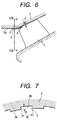
- Fig. 6 shows an example of the second embodiment of the present invention.
- a II-II cross section view of Fig. 6 is shown in Fig. 7.
- an inner wall 2a i.e., the flow surface
- the groove is constructed with a convex portion 3a of height D projecting from the inner wall 2a of the casing and a concave portion 3b at the height being equal to that of the inner wall 2a.
- the width (W) is, for example, approximately from 5 mm to 150 mm, in more preferable from 8 mm to 30 mm, and the height (depth) of the grooves is from approximately 0.1 times to 0.3 times of the width of the grooves corresponding thereto, for example, approximately from 0.5 mm to 30 mm, in more preferable from 1.5 mm to 6 mm.
- the blade of the impeller is made in such a form that, in height thereof, a distance ⁇ at the blade tip for the normal open-type impeller can be maintained, in particular in the configuration on the meridian plane including the convex portion of the grooves at a static side.
- the fluid increased up in pressure by the blades flows backward in the groove 3, directing from the terminal position a at the downstream side to the terminal position b at the upper stream side, and is injected into the spot of the recirculation occurring when the flow rate is low, thereby preventing from generation of the swirl due to the forward component of the recirculation at the spot where the recirculation occurs.
- the head-capacity characteristic curve is resolved from the portion uprising at the right-hand side therein, thereby becoming a stable curve without the behavior uprising at the right-hand side.
- the tool can pass through without stopping at the end edge of the grooves in the processing of thereof, in particular in the machining process, therefore the efficiency in the machining can be improved.
- FIG. 8 A (first) variation according to the second embodiment of the present invention is shown in Fig. 8.
- the casing 2 at the static side is constructed with a static side casing liner 2c including the grooves therein, and static side casing liners 2d and 2e without the grooves, and those static side casing liners 2c, 2d and 2e being made as separated elements are positioned in an axial direction thereof.
- the machining of the grooves 3 must be performed only on the casing liner to be formed with such the grooves therein, as a one part, and the end edge portion of the grooves are opened, therefore the efficiency in the machining can be improved much more.
- FIG. 9 Another (a second) variation of the second embodiment of the present invention is shown in Fig. 9.
- the casing 2 at the static side is constructed with a static side casing liner 2c including the grooves therein, and static side casing liners 2d and 2f without the grooves, however the stationary side casing liner 2c including the grooves is made as a separated element being divided from the stationary side casing liner 2f without the grooves in a radial direction thereof.
- the casing with the grooves can be treated as a one part in the machining of the grooves 3, and the end edge portion of the grooves are opened, therefore the efficiency in the machining can be improved much more.
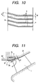
- FIG. 10 An example of the configuration of the grooves according to the second embodiment of the present invention is shown in Fig. 10.
- a starting end of the groove 3 located at the upper stream side of the impeller 1 is inclined only by an angle ⁇ in the rotating direction of the impeller from a direction of the pump axis.
- the head-capacity characteristic curve which the impeller can outputs theoretically is not decreased down, then a stable head-capacity characteristic curve can be obtained thererom.
- the reverse flow of the recirculation reaches further to a side in the stream upper than the recirculation area mentioned above.
- the direction of the grooves at that location is, not in the direction of the pump axis, but is inclined by the angle ⁇ into the rotation direction of the impeller.
- the head-capacity characteristic curve which the impeller can output theoretically falls down comparing to the case where the grooves are formed in parallel to the pump axis, and following therewith, an axial motive power consumed for rotating the impeller also falls down, thereby obtaining reduction in an axial motive power for closure.
- the configuration of the grooves as shown in Fig. 10 it is possible to obtain, not only the stability of the head-capacity characteristic curve, but also the reduction in the axis motive power for closure, thereby obtaining the mixed-flow pump having a superior characteristics therewith.
- FIG. 11 A further other (a third) variation according to the second embodiment of the present invention is shown in Fig. 11.
- the convex portion 3a of the groove 3 is made larger than the configuration of the flow passage of the stationary side casing liner 2f without the groove being extended into a suction side as it is, in the distance of the radial direction from the rotation center of the pump.
- each the blade of the impeller is constructed so that the height of thereof at the downstream side is lower than that at the upstream side by ⁇ 2 in the vicinity of the terminal a of the groove.
- the instability of the head-capacity characteristic curve can be lessened even in the case where the grooves 3 are not formed, as well as in the case where the grooves 3 are provided, and the instability of the head-capacity characteristic curve (i.e., the behavior of uprising at the right-hand side in the head-capacity characteristic curve) can be removed with certainty.
- the convex portion 3a defining the starting end b of the groove 3 is formed in an inclined direction. And, this starting end 2b is provided in the vicinity of the portion where the flow passage is wound from the portion in parallel with the axis of the casing 2 into the direction of the external diameter thereof.
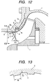
- Fig. 12 shows an example according to the present invention
- Fig. 13 shows a VIII-VIII cross section view of Fig. 12.
- a shroud 1a thereabouts.
- This shroud 1a is not provided in the vicinity of the inlet 1c of the impeller, therefore the impeller is made as an impeller of a semi-open type having the shroud in a part.
- a mouth ring portion 1b At the most inner diameter of the shroud is provided a mouth ring portion 1b, and on an inner surface of the casing as the stationary side is provided a casing ring 5.
- a sealing portion of the rotation axis 3 is defined between those mouth ring portion 1b and the casing ring 5.
- a plurality of the grooves 3 are formed aligning at the same distance in the axial direction thereof.
- the terminal a at the downstream side of the groove resides at a position entering into the downstream side from a front edge of the blade a little bit (i.e., the position being adjacent to the mouth ring portion in the vicinity of the inlet 1c of the impeller),while the terminal position b thereof at the upstream side resides at the side in stream being upper than the blades of the impeller.
- a portion 2g of the casing 2 opposing to an end surface 1d of the shroud of the impeller is provided at the position being same to the downstream side terminal position a of the groove 3 in the axial direction thereof.
- the surface 2g of the casing 2 in a direction being orthogonal to the axis thereof and the end surface 1d of the shroud are positioned with the aperture ⁇ 1 in the axial direction therebetween.
- the head which can be outputted theoretically by the impeller is increased up, and the head-capacity characteristic curve can be resolved from the unstable portion, thereby obtaining the stability thereof.
- the closed-type impeller having the shroud thereabouts, it is possible to obtain the stability of the head-capacity characteristic curve with the provision of the grooves 3 in the casing 2, i.e., the head-capacity characteristic curve shows the behavior continuously falling down at the right-hand side, and therefore it is possible to obtain a pump characteristic being stable.
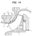
- Fig. 14 shows a (first) variation of the third embodiment according to the present invention.
- the casing 2 is constructed with the casing liners 2c, 2d and 2e which are divided in the axial direction thereof, and the grooves 3 are formed in the casing liner 2c which is provided at the inlet portion of the impeller.
- the grooves 3 are formed in the configuration being same to those in the respective examples mentioned in the above. According to this example, since grooves 3 are opened at both ends thereof, it is also possible to machine the grooves 3 by means of the tool with ease.
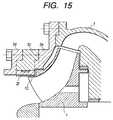
- Fig. 15 shows another (second) variation of the third embodiment according to the present invention.
- the casing 2 is constructed with the casing liners 2c, 2d, 2e and 2f which are divided in the axial direction thereof, and further the casing liners 2c and 2f are divided into the radial direction thereof.
- the grooves 3 are formed in the casing liner 2f at the inner diameter side, which is provided at the inlet portion of the impeller. Also in this example, the grooves 3 are formed in the configuration being same to those in the respective examples mentioned in the above. According to this example, since the casing liner 2f in which the grooves 3 are formed can be made smaller than the part 2c shown in Fig. 14, therefore it is possible to machine the grooves 3 by means of the tool with much ease.
- the present invention also can be applied to other turbo machines, such as a centrifugal pump, a mixed-flow air blower, a mixed-flow compressor, etc., each having the open-type impeller or the closed-type impeller.
- the configuration of the grooves 3 are studied, being preferable for removing the behavior of uprising at the right-hand side, in particular in the head-flow rate characteristic of the turbo machine, as well as for suppressing the decrease in the efficiency thereof, and there can be found the following index (hereinafter, being called by "JE No.") relating to an appropriate configuration of those grooves.
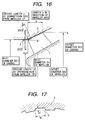
- the total volume of the grooves can be obtained by " number of the grooves N ⁇ grooves length L ⁇ groove width W ⁇ groove depth D ", while the volume of the impeller by " inlet area of the impeller ⁇ axial direction length at the tip of the impeller Li ".
- the inlet area of the impeller can be obtained from an inlet diameter Di1 of the impeller.
- the grooves length L is "L1 + L2" in the Fig. 16.
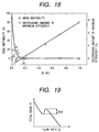
- Fig. 18 shows the experimental results by applying the above JE No.
- a horizontal axis indicates the JE No.
- An vertical axis at the left-hand side indicates the instability of head (%), and it is defined by the following equation, which indicates an amount decreased at the unstable portion of the head-flow rate characteristic curve, being represented by a ratio between the decreasing amount ⁇ 0 when no groove is formed and the decreasing amount ⁇ when the grooves are formed.
- Head instability (%) ( ⁇ / ⁇ 0 ) ⁇ 100
- each of the decreasing amounts ⁇ and ⁇ 0 is obtained, as shown in Fig. 19, from a difference between the maximum value and the minimum value in the unstable portion (i.e., the portion showing the behavior of uprising at the right-hand side) of the head-flow rate characteristic curve.
- the ⁇ is an finite value when there is the instability in the head (i.e., when it shows the behavior uprising at the right-hand side), on the other hand it is zero (0) when there is no such the instability in the head (i.e., when it does not shows such the behavior uprising at the right-hand side).
- the unstable portion of the head-flow rate characteristic curve is distinguished completely due to the function of the grooves when the head instability is at 0%, while that no effect can be obtained from the grooves and then no improvement can be achieved in the instability at all when the head instability is at 100%. Further, when the head instability lies between 0% and 100%, it means that, through the instability of the head is not extinguished completely, but the unstable portion is improved by the grooves to a certain degree.
- a vertical axis at the right-hand side in Fig. 18 indicates the decreasing amount (%) of the maximum efficiency, and it means the difference in the maximum efficiency (%) between when the grooves are provided in the same pump and when no groove is provided therein. Namely, it is 0% if no change occurs in the maximum efficiency of the pump between before and after the provision of grooves, and it has a plus value when the decrease occurs in the efficiency by the provision of the grooves, for example, 3% means that the decrease of 3% occurs in the efficiency with the provision of the grooves.
- the head instability exceeds 80% in the characteristic curve thereof when the JE No. come to be equal or smaller than 0.03, then the effect of the grooves becomes small abruptly.
- the JE No. is in the vicinity of 0.03, the head instability is improved to be approximately 30%, and when it exceeds 0.03, the head instability is further improved.
- the instability is 0% when the JE No. is 0.15, more or less, i.e., it can be seen that the instability is dissolved.
- the JE No. exceeds 0.15, the head instability is stable as it is at 0%. From this fact, in view point of obtaining the stability in the head, the JE No.
- the decreasing amount in the maximum efficiency is 0% or less than that until the JE No. comes up to be 0.15, or more or less, however if it exceeds 0.15, the decreasing amount of the maximum efficiency becomes large in proportion to that JE No.
- the JE No. is preferable to be equal or less than 0.5. Accordingly, from view points of both the head stability and the efficiency, it is preferable to set an appropriate range from 0.03 to 0.5 for the JE No., and it is most suitable that the JE No. is selected to be from 0.15 to 0.2, as a condition for dissolving the instability completely but without decrease in the efficiency.
- the experimental results shown in Fig. 18 are for the pump at 830 of the specific velocity thereof, for example, however similar results can be obtained also in the case where the same experiments are made on the mixed-flow pumps of the specific velocity of 1,250 and 1,400. Therefore, it can be ascertained that the configuration of the grooves can be determined by using the JE No. being as the above-mentioned index, at least in the range from 800 up to 1,400 in the specific velocity. Further, it can be considered that the configuration of the grooves also can be determined by using the JE No. for those being from 300 up to 2,000 in the specific velocity thereof.
- a portion of fluid being increased in pressure by itself flows backward in a flow passage formed in the casing to be injected into the spot where the recirculation occurs, i.e., the flow without the swirl from the grooves suppresses the swirl component in the reverse flow being turned back from the impeller and forming the recirculation, therefore no swirl is generated in the fluid flowing into the impeller, thereby suppressing the generation of the swirl due to the recirculation at the inlet of the impeller, as well as suppressing the rotating stall thereof, then it is possible to remove the behavior uprising at the right-hand side in the head-flow rate characteristic curve of the turbo machine.
- the turbo machine having the closed-type impeller with the shroud thereabouts by making the impeller as the semi-open structure without the shroud at the portion in vicinity of the inlet thereof and with provision of the grooves on the inner wall surface (i.e., the flow surface) of the casing in the direction of pressure gradient, corresponding to the portion of the impeller, thereby it is possible to realize the turbo machine with ease, being stable in the head-capacity characteristic curve even in operating at the low flow rate where the recirculation occurs, as well as, bring about almost no decrease in the efficiency of the turbo machine.
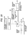
- FIG. 20 a block diagram of a pump station in which the present invention is applied to, however, such as a drainage pump for example, in a drainage pump station, other than the water circulating pumps in a thermal power plant or in a nuclear power plant as mentioned above.
- the pump station includes a pump 200, such as the mixed-flow pump in which the shallow grooves are formed in the casing corresponding to the impeller, in particular in the portion at the inlet portion thereof.
- the impeller of the pump is ratably driven with an rotating axis thereof by means of a driver apparatus (or driver) 210, comprising such as a diesel engine, a gas turbine, an electric motor, etc., for example.
- the rotating velocity or speed of the driver apparatus 210 is controlled by a pump speed control equipment 220, being constructed with an electric circuitry or a micro-computer unit for that purpose, for example. And, as is connected with a broken line, a blade angle control equipment 230 is further provided, if necessary, for controlling an inclination angle of the blades of the impeller depending upon the change in flow rate of the fluid flowing into the impeller.
- the pump 200 having such the structure mentioned in the above, has a bell mouth 201 dipping into water in a suction sump or passage 240 and a discharge pipe or conduit 250 connected to a discharge sump or passage 260 being distant from the suction sump or passage. And, by the operation of the pump station mentioned above, the water head, i.e., the suction water level is increased or lifted up to the discharge water level in the discharge sump or passage 260, including the flow resistance within the flow passage of the fluid, i.e., in the discharge pipe 250.
- the behavior uprising at the right-hand side appears remarkably in a part of the head-capacity characteristic curve thereof, in particular from 50 % to 70 % in the flow rate thereof, thereby bringing the operation of the pump into unstable condition, or alternatively that, though not bringing about such the behavior uprising at the right-hand side remarkably, but the head-capacity characteristic curve comes to be flat in a portion thereof, also in the region from 50 % to 70 % of the flow rate thereof.
- an operating flow rate by the pump of the pump station is determined at a point intersecting between a static head which is determined as a difference between the water heads or levels at the suction side and the discharge side in the pump station, a resistance curve which is determined by summing up resistance in the flow passage or pipes in the pump station, and the head-capacity characteristic curve of the pump. If there is a region uprising at the right-hand side in the head-capacity characteristic curve, there can be a case where the head-capacity characteristic curve intersects with the resistance curve at a plurality points. In such the instance, it is impossible to determine the crossing point at only one point, i.e., the flow rate cannot be determined uniquely, therefore the flow rate cannot be determined. In particular, it is remarkable when the stationary head is high and the pipe resistance is small.
- the pump is controlled so that it is operated only in the region where no such the unstable operation occurs, by establishing an operating rule for that pump. Accordingly, in the pump station with which the operating region is controlled by the rotation speed of the pump, the rotating speed is only controllable or restricted within that region as for as being in the stable region, i.e., not entering into the unstable region.
- a pump station with which the rotation speed can be altered in a wide rage, by using the mixed-flow pump, having the head-flow rate characteristic curve without such the behavior of uprising at the right-hand side and being able to achieve higher efficiency, thereby obtaining a pump station which can be operated in a wide rage of the flow rate.
- the feature of the present invention lies in that, in the pump station in which the operating region of the pump is controlled by the rotation speed thereof, the pump being used in that pump station is the mixed-flow pump into which is applied any one of the casings having such the grooves as mentioned heretofore.
- the rotation speed of the pump can be controlled in a control range from 60% to 100% with respect to a reference rotation speed, in a case where a driver apparatus for the pump comprises a speed reduction gear, a fluid coupling and a diesel engine. Also, the rotation speed can be controlled in the control range from 60% to 100% with respect to the reference rotation speed, in a case where the driving apparatus for the pump comprises a speed reduction gear, a fluid coupling and a gas turbine. Further, the driving apparatus for the pump comprises an electric motor which controls the rotation speed by an inverter, and in that case, the rotation speed thereof can be controlled in the control range from 0% to 100% with respect to a reference rotation speed.
- Fig. 21 shows an example of the head-capacity characteristic curve of the pump of that pump station, into which is applied one of the mixed-flow pumps according to the present invention mentioned in the above.
- the horizontal axis indicates the flow rate by the ratio of flow rate %Q assuming that a designed flow rate as a reference is at 100%, while the vertical axis a head ratio %H assuming that a designed total head as a reference is at 100%.
- a head curve 10 shows a characteristic of one example of the mixed-flow pump according to the present invention when the reference rotation number is 100%N, and shows a tendency of falling down at the right-hand side all over the region, therefore there is no unstable region.
- the head curve 14 shows a characteristic at 100%N in a case where the present invention is not applied to, wherein it is unstable at 50%Q, or more or less than that, and in this case, there lies the unstable region in a range from 40%Q to 70%Q.
- a resistance curve 18 is a characteristic of the present pump station. When the pump is operated at 100%N, the intersection point between the head curve 10 and the resistance curve 18 or between 14 and that is only one point, i.e., at a point A, therefore in either case, the pump can be operated with stability at the point A.
- the stable head curve 10 of the pump is shifted down to a head curve 11, while the unstable head curve 14 down to a head curve 15.
- the operating point in this instance is at a point B, therefore the pump can be operated with stability irrespective of the unstable region in the head curve.
- the rotation number is further decreased down to 74%N, according to the law of similarity mentioned above, the head curve 10 having no such the instability according to the present invention is shifted down to a head curve 12, wherein the intersection point between the resistance curve 18 is only one point at a point C, i.e., the operating point is at the point C.
- the head curve 14 having the instability therein is shifted down to a head curve 16 at 74%N, wherein it is almost in parallel to the resistance curve 18 in the vicinity from 30%Q to 50%Q.
- intersection point of the head curve 16 between the resistance curve cannot be determined at only one point, but there may be plural intersection points threbetween. Accordingly, the flow rate point cannot be determined uniquely, and then the operation of the pump is fluctuated in a range of the instability from 30%Q to 50%Q on that head curve to be out of control, therefore the operation cannot be performed from 30%Q to 50%Q.
- the head curve 10 having no such the instability according to the present invention is shifted down to a head curve 13, while the head curve 14 having the instability therein down to a head curve 17.
- the intersection point between the resistance curve 18 is determined at only one point , i.e., a point D, in either case of the head curves 13 and 17, therefore the operation of the pump is possible.
- the pump cannot be operated in the range from 30%Q to 50%Q at the rotation speed 74%N, then the region in which the pump can be operated comes to be in discontinuity. Therefore, the pump speed is from 74%N to 100%N in the region thereof, and the operation area of the pump lies between the pint A and the point C.
- the mixed-flow pump according to the present invention can be operated with the stability at the rotation speed being equal or less than that, therefore the operation can be performed all over the wide range in flow rate from the point A to the point D.
- the driver apparatus for the pump comprises the speed reduction gear, the fluid coupler, and the diesel engine, wherein the operation is possible from the point A to the point D shown in Fig. 21 when the control range in the rotation speed is from 60% to 100% with respect to the reference rotation speed.
- Another driver apparatus for the pump comprises the speed reduction gear, the fluid coupler, and the gas turbine, wherein the operation is also possible from the point A to the point D shown in Fig. 21 when the control range in the rotation speed is from 60% to 100% with respect to the reference rotation speed.
- the other driver apparatus comprises the electric motor which control the rotation speed by the inverter, wherein the operation range is widen further when the control range in the rotation speed is from 0% to 100% with respect to the reference rotation speed. This is, because the rotation speed can be decreased down until a point in the vicinity of the point E in Fig. 21, the operation of the pump is possible in a range from almost 0%Q up to 100%Q.
- the improved pump according to the present invention into, since the efficiency hardly falls down while can be obtained the head-capacity characteristic curve being stable in the mixed-flow pump, there can be obtained the pump station, in which the range of the rotation speed can be widen much more and the operation can be realized in a wide flow rate range with ease.
Landscapes
- Engineering & Computer Science (AREA)
- Mechanical Engineering (AREA)
- General Engineering & Computer Science (AREA)
- Life Sciences & Earth Sciences (AREA)
- Sustainable Development (AREA)
- Structures Of Non-Positive Displacement Pumps (AREA)
- Turbine Rotor Nozzle Sealing (AREA)
Applications Claiming Priority (2)
| Application Number | Priority Date | Filing Date | Title |
|---|---|---|---|
| JP20130299 | 1999-07-15 | ||
| JP20130299 | 1999-07-15 |
Publications (3)
| Publication Number | Publication Date |
|---|---|
| EP1069315A2 true EP1069315A2 (de) | 2001-01-17 |
| EP1069315A3 EP1069315A3 (de) | 2002-05-29 |
| EP1069315B1 EP1069315B1 (de) | 2007-09-12 |
Family
ID=16438754
Family Applications (1)
| Application Number | Title | Priority Date | Filing Date |
|---|---|---|---|
| EP00114868A Expired - Lifetime EP1069315B1 (de) | 1999-07-15 | 2000-07-11 | Turbomaschinen |
Country Status (4)
| Country | Link |
|---|---|
| EP (1) | EP1069315B1 (de) |
| CN (1) | CN1221741C (de) |
| AT (1) | ATE373175T1 (de) |
| DE (1) | DE60036336T2 (de) |
Cited By (8)
| Publication number | Priority date | Publication date | Assignee | Title |
|---|---|---|---|---|
| EP1247991A1 (de) * | 2001-04-05 | 2002-10-09 | Hitachi, Ltd. | Kreiselpumpe |
| DE10258922A1 (de) * | 2002-12-17 | 2004-07-01 | Ksb Aktiengesellschaft | Saugkanal |
| FR2912789A1 (fr) * | 2007-02-21 | 2008-08-22 | Snecma Sa | Carter avec traitement de carter, compresseur et turbomachine comportant un tel carter. |
| EP2031184A1 (de) * | 2007-08-31 | 2009-03-04 | Siemens Aktiengesellschaft | Drallbrecher für eine Strömungsmaschine |
| US8690523B2 (en) | 2008-10-21 | 2014-04-08 | Rolls-Royce Deutschland Ltd & Co Kg | Fluid flow machine with running gap retraction |
| WO2015130522A1 (en) * | 2014-02-25 | 2015-09-03 | Siemens Aktiengesellschaft | Turbine ring segment with abradable surface having ridges with inclined lateral walls |
| US10221716B2 (en) | 2014-02-25 | 2019-03-05 | Siemens Aktiengesellschaft | Turbine abradable layer with inclined angle surface ridge or groove pattern |
| CN113217458A (zh) * | 2021-05-28 | 2021-08-06 | 宁波方太厨具有限公司 | 一种叶轮、应用有该叶轮的风机系统和吸油烟机 |
Families Citing this family (12)
| Publication number | Priority date | Publication date | Assignee | Title |
|---|---|---|---|---|
| CN1323225C (zh) * | 2003-07-16 | 2007-06-27 | 沈阳黎明航空发动机(集团)有限责任公司 | 一种利用涡轮风扇发动机改制成工业燃机的方法 |
| KR100568183B1 (ko) * | 2004-01-08 | 2006-04-05 | 삼성전자주식회사 | 터보압축기 |
| FR2961564B1 (fr) * | 2010-06-17 | 2016-03-04 | Snecma | Compresseur et turbomachine a rendement optimise |
| CN102817873B (zh) * | 2012-08-10 | 2015-07-15 | 势加透博(北京)科技有限公司 | 航空发动机压气机的梯状间隙结构 |
| CN102927052B (zh) * | 2012-11-12 | 2015-03-04 | 西安交通大学 | 径向槽机匣处理方法 |
| CN104279181B (zh) * | 2014-09-26 | 2017-06-06 | 清华大学 | 离心泵叶轮 |
| CN104389800B (zh) * | 2014-10-15 | 2017-04-12 | 陈远进 | 航空发动机混流压气机 |
| CN105134659B (zh) * | 2015-08-25 | 2017-10-31 | 浙江理工大学 | 基于能量梯度理论的离心压缩机弯道改进方法 |
| CN106438475A (zh) * | 2016-09-18 | 2017-02-22 | 江苏大学 | 一种抑制叶顶泄漏流的斜流泵 |
| CN108050074A (zh) * | 2017-11-09 | 2018-05-18 | 西安理工大学 | 一种能提高轴流泵性能稳定性的进口锥管 |
| CN109882448B (zh) * | 2019-02-25 | 2020-06-26 | 江苏大学 | 一种具有圆弧形泵送槽的混流泵转轮室 |
| DE102023127949A1 (de) * | 2023-10-12 | 2025-04-17 | Oase Gmbh | Strömungspumpe |
Citations (1)
| Publication number | Priority date | Publication date | Assignee | Title |
|---|---|---|---|---|
| US4212585A (en) | 1978-01-20 | 1980-07-15 | Northern Research And Engineering Corporation | Centrifugal compressor |
Family Cites Families (4)
| Publication number | Priority date | Publication date | Assignee | Title |
|---|---|---|---|---|
| GB2146707B (en) * | 1983-09-14 | 1987-08-05 | Rolls Royce | Turbine |
| GB2245312B (en) * | 1984-06-19 | 1992-03-25 | Rolls Royce Plc | Axial flow compressor surge margin improvement |
| US4781530A (en) * | 1986-07-28 | 1988-11-01 | Cummins Engine Company, Inc. | Compressor range improvement means |
| CZ48394A3 (en) * | 1993-03-04 | 1994-09-14 | Abb Management Ag | Radial-flow compressor with a flow-stabilizing casing |
-
2000
- 2000-07-11 EP EP00114868A patent/EP1069315B1/de not_active Expired - Lifetime
- 2000-07-11 AT AT00114868T patent/ATE373175T1/de active
- 2000-07-11 DE DE60036336T patent/DE60036336T2/de not_active Expired - Lifetime
- 2000-07-14 CN CN00120383.5A patent/CN1221741C/zh not_active Expired - Fee Related
Patent Citations (1)
| Publication number | Priority date | Publication date | Assignee | Title |
|---|---|---|---|---|
| US4212585A (en) | 1978-01-20 | 1980-07-15 | Northern Research And Engineering Corporation | Centrifugal compressor |
Cited By (12)
| Publication number | Priority date | Publication date | Assignee | Title |
|---|---|---|---|---|
| EP1247991A1 (de) * | 2001-04-05 | 2002-10-09 | Hitachi, Ltd. | Kreiselpumpe |
| US6514034B2 (en) | 2001-04-05 | 2003-02-04 | Hitachi, Ltd. | Pump |
| DE10258922A1 (de) * | 2002-12-17 | 2004-07-01 | Ksb Aktiengesellschaft | Saugkanal |
| US7798772B2 (en) | 2002-12-17 | 2010-09-21 | Ksb Aktiengesellschaft | Centrifugal pump intake channel |
| FR2912789A1 (fr) * | 2007-02-21 | 2008-08-22 | Snecma Sa | Carter avec traitement de carter, compresseur et turbomachine comportant un tel carter. |
| EP1961920A1 (de) * | 2007-02-21 | 2008-08-27 | Snecma | Gehäuse mit Gehäusebehandlung, Kompressor und Turbinentriebwerk, das ein solches Gehäuse umfasst |
| US8100629B2 (en) | 2007-02-21 | 2012-01-24 | Snecma | Turbomachine casing with treatment, a compressor, and a turbomachine including such a casing |
| EP2031184A1 (de) * | 2007-08-31 | 2009-03-04 | Siemens Aktiengesellschaft | Drallbrecher für eine Strömungsmaschine |
| US8690523B2 (en) | 2008-10-21 | 2014-04-08 | Rolls-Royce Deutschland Ltd & Co Kg | Fluid flow machine with running gap retraction |
| WO2015130522A1 (en) * | 2014-02-25 | 2015-09-03 | Siemens Aktiengesellschaft | Turbine ring segment with abradable surface having ridges with inclined lateral walls |
| US10221716B2 (en) | 2014-02-25 | 2019-03-05 | Siemens Aktiengesellschaft | Turbine abradable layer with inclined angle surface ridge or groove pattern |
| CN113217458A (zh) * | 2021-05-28 | 2021-08-06 | 宁波方太厨具有限公司 | 一种叶轮、应用有该叶轮的风机系统和吸油烟机 |
Also Published As
| Publication number | Publication date |
|---|---|
| DE60036336D1 (de) | 2007-10-25 |
| CN1281953A (zh) | 2001-01-31 |
| ATE373175T1 (de) | 2007-09-15 |
| EP1069315A3 (de) | 2002-05-29 |
| DE60036336T2 (de) | 2008-06-12 |
| EP1069315B1 (de) | 2007-09-12 |
| CN1221741C (zh) | 2005-10-05 |
Similar Documents
| Publication | Publication Date | Title |
|---|---|---|
| US6527509B2 (en) | Turbo machines | |
| EP1069315B1 (de) | Turbomaschinen | |
| US6290458B1 (en) | Turbo machines | |
| JP4295611B2 (ja) | 流れ安定化装置 | |
| EP1270953B1 (de) | Axial durchströmte Hydraulikmaschine | |
| US6302643B1 (en) | Turbo machines | |
| JPWO2016178387A1 (ja) | 横軸水中ポンプ、及び、横軸水中ポンプに用いられる吸込カバー | |
| JP3841391B2 (ja) | ターボ機械 | |
| JP3862135B2 (ja) | ターボ機械及びそれを利用したポンプ機場 | |
| EP1134427A1 (de) | Turbomaschinen | |
| JP2002098099A (ja) | ターボ形水力機械 | |
| JP2017020432A (ja) | ポンプ用羽根車及びこれを備えたポンプ | |
| JP2005069048A (ja) | 立軸ポンプ及びその運転方法 | |
| CN120292117A (zh) | 油气混输泵叶顶泄漏流抑制结构、设计方法及油气混输泵 | |
| US5154570A (en) | Vertical shaft pump | |
| CN1314552A (zh) | 涡轮机 | |
| JP4079740B2 (ja) | 軸流形流体機械 | |
| CN1248313A (zh) | 带抽吸盖内侧通道避免产生损耗的涡流结构的带侧通道泵 | |
| WO2019171774A1 (ja) | 立軸ポンプ | |
| JP2000303995A (ja) | 羽根入口再循環流および羽根旋回失速を抑制したターボ機械 | |
| JP3345616B2 (ja) | 省スペース排水機場 | |
| JP3111548B2 (ja) | 立軸ポンプ | |
| JPH01315691A (ja) | 立軸形ポンプ | |
| JPH08247080A (ja) | 渦巻斜流ポンプ | |
| JPH09119391A (ja) | 立軸ポンプ |
Legal Events
| Date | Code | Title | Description |
|---|---|---|---|
| PUAI | Public reference made under article 153(3) epc to a published international application that has entered the european phase |
Free format text: ORIGINAL CODE: 0009012 |
|
| 17P | Request for examination filed |
Effective date: 20000711 |
|
| AK | Designated contracting states |
Kind code of ref document: A2 Designated state(s): AT BE CH CY DE DK ES FI FR GB GR IE IT LI LU MC NL PT SE |
|
| AX | Request for extension of the european patent |
Free format text: AL;LT;LV;MK;RO;SI |
|
| PUAL | Search report despatched |
Free format text: ORIGINAL CODE: 0009013 |
|
| AK | Designated contracting states |
Kind code of ref document: A3 Designated state(s): AT BE CH CY DE DK ES FI FR GB GR IE IT LI LU MC NL PT SE |
|
| AX | Request for extension of the european patent |
Free format text: AL;LT;LV;MK;RO;SI |
|
| RIC1 | Information provided on ipc code assigned before grant |
Free format text: 7F 04D 29/42 A, 7F 04D 27/02 B, 7F 04D 29/66 B, 7F 04D 29/68 B |
|
| AKX | Designation fees paid |
Designated state(s): AT CH DE FR GB IT LI |
|
| GRAP | Despatch of communication of intention to grant a patent |
Free format text: ORIGINAL CODE: EPIDOSNIGR1 |
|
| GRAS | Grant fee paid |
Free format text: ORIGINAL CODE: EPIDOSNIGR3 |
|
| RAP1 | Party data changed (applicant data changed or rights of an application transferred) |
Owner name: HITACHI PLANT TECHNOLOGIES, LTD. Owner name: KUROKAWA, JUNICHI |
|
| GRAA | (expected) grant |
Free format text: ORIGINAL CODE: 0009210 |
|
| AK | Designated contracting states |
Kind code of ref document: B1 Designated state(s): AT CH DE FR GB IT LI |
|
| REG | Reference to a national code |
Ref country code: GB Ref legal event code: FG4D |
|
| REG | Reference to a national code |
Ref country code: CH Ref legal event code: EP |
|
| REF | Corresponds to: |
Ref document number: 60036336 Country of ref document: DE Date of ref document: 20071025 Kind code of ref document: P |
|
| REG | Reference to a national code |
Ref country code: CH Ref legal event code: NV Representative=s name: TROESCH SCHEIDEGGER WERNER AG |
|
| RAP2 | Party data changed (patent owner data changed or rights of a patent transferred) |
Owner name: KUROKAWA, JUNICHI Owner name: HITACHI PLANT TECHNOLOGIES, LTD. |
|
| ET | Fr: translation filed | ||
| PLBE | No opposition filed within time limit |
Free format text: ORIGINAL CODE: 0009261 |
|
| STAA | Information on the status of an ep patent application or granted ep patent |
Free format text: STATUS: NO OPPOSITION FILED WITHIN TIME LIMIT |
|
| 26N | No opposition filed |
Effective date: 20080613 |
|
| REG | Reference to a national code |
Ref country code: DE Ref legal event code: R082 Ref document number: 60036336 Country of ref document: DE Representative=s name: V. FUENER EBBINGHAUS FINCK HANO, DE |
|
| REG | Reference to a national code |
Ref country code: GB Ref legal event code: 732E Free format text: REGISTERED BETWEEN 20140220 AND 20140226 |
|
| REG | Reference to a national code |
Ref country code: DE Ref legal event code: R081 Ref document number: 60036336 Country of ref document: DE Owner name: KUROKAWA, JUNICHI, JP Free format text: FORMER OWNER: HITACHI PLANT TECHNOLOGIES, LTD,JUNICHI KUROKAWA, , JP Effective date: 20140218 Ref country code: DE Ref legal event code: R082 Ref document number: 60036336 Country of ref document: DE Representative=s name: V. FUENER EBBINGHAUS FINCK HANO, DE Effective date: 20140218 Ref country code: DE Ref legal event code: R081 Ref document number: 60036336 Country of ref document: DE Owner name: HITACHI, LTD., JP Free format text: FORMER OWNER: HITACHI PLANT TECHNOLOGIES, LTD,JUNICHI KUROKAWA, , JP Effective date: 20140218 Ref country code: DE Ref legal event code: R081 Ref document number: 60036336 Country of ref document: DE Owner name: KUROKAWA, JUNICHI, YOKOHAMA, JP Free format text: FORMER OWNER: HITACHI PLANT TECHNOLOGIES, LTD,JUNICHI KUROKAWA, , JP Effective date: 20140218 Ref country code: DE Ref legal event code: R081 Ref document number: 60036336 Country of ref document: DE Owner name: HITACHI, LTD., JP Free format text: FORMER OWNERS: HITACHI PLANT TECHNOLOGIES, LTD., TOKIO, JP; KUROKAWA, JUNICHI, YOKOHAMA, KANAGAWA, JP Effective date: 20140218 Ref country code: DE Ref legal event code: R081 Ref document number: 60036336 Country of ref document: DE Owner name: KUROKAWA, JUNICHI, YOKOHAMA, JP Free format text: FORMER OWNERS: HITACHI PLANT TECHNOLOGIES, LTD., TOKIO, JP; KUROKAWA, JUNICHI, YOKOHAMA, KANAGAWA, JP Effective date: 20140218 |
|
| REG | Reference to a national code |
Ref country code: GB Ref legal event code: 732E Free format text: REGISTERED BETWEEN 20140313 AND 20140319 |
|
| REG | Reference to a national code |
Ref country code: FR Ref legal event code: TQ Owner name: JUNICHI KUROKAWA, JP Effective date: 20140612 Ref country code: FR Ref legal event code: TQ Owner name: HITACHI, LTD., JP Effective date: 20140612 |
|
| REG | Reference to a national code |
Ref country code: AT Ref legal event code: PC Ref document number: 373175 Country of ref document: AT Kind code of ref document: T Owner name: HITACHI, LTD., JP Effective date: 20140924 Ref country code: AT Ref legal event code: PC Ref document number: 373175 Country of ref document: AT Kind code of ref document: T Owner name: KUROKAWA, JUNICHI, JP Effective date: 20140924 |
|
| REG | Reference to a national code |
Ref country code: FR Ref legal event code: PLFP Year of fee payment: 17 |
|
| PGFP | Annual fee paid to national office [announced via postgrant information from national office to epo] |
Ref country code: FR Payment date: 20160613 Year of fee payment: 17 |
|
| PGFP | Annual fee paid to national office [announced via postgrant information from national office to epo] |
Ref country code: DE Payment date: 20160705 Year of fee payment: 17 Ref country code: GB Payment date: 20160706 Year of fee payment: 17 Ref country code: CH Payment date: 20160712 Year of fee payment: 17 Ref country code: IT Payment date: 20160720 Year of fee payment: 17 |
|
| PGFP | Annual fee paid to national office [announced via postgrant information from national office to epo] |
Ref country code: AT Payment date: 20160630 Year of fee payment: 17 |
|
| REG | Reference to a national code |
Ref country code: DE Ref legal event code: R119 Ref document number: 60036336 Country of ref document: DE |
|
| REG | Reference to a national code |
Ref country code: CH Ref legal event code: PL |
|
| REG | Reference to a national code |
Ref country code: AT Ref legal event code: MM01 Ref document number: 373175 Country of ref document: AT Kind code of ref document: T Effective date: 20170711 |
|
| GBPC | Gb: european patent ceased through non-payment of renewal fee |
Effective date: 20170711 |
|
| REG | Reference to a national code |
Ref country code: FR Ref legal event code: ST Effective date: 20180330 |
|
| PG25 | Lapsed in a contracting state [announced via postgrant information from national office to epo] |
Ref country code: DE Free format text: LAPSE BECAUSE OF NON-PAYMENT OF DUE FEES Effective date: 20180201 Ref country code: CH Free format text: LAPSE BECAUSE OF NON-PAYMENT OF DUE FEES Effective date: 20170731 Ref country code: GB Free format text: LAPSE BECAUSE OF NON-PAYMENT OF DUE FEES Effective date: 20170711 Ref country code: LI Free format text: LAPSE BECAUSE OF NON-PAYMENT OF DUE FEES Effective date: 20170731 |
|
| PG25 | Lapsed in a contracting state [announced via postgrant information from national office to epo] |
Ref country code: AT Free format text: LAPSE BECAUSE OF NON-PAYMENT OF DUE FEES Effective date: 20170711 Ref country code: FR Free format text: LAPSE BECAUSE OF NON-PAYMENT OF DUE FEES Effective date: 20170731 |
|
| PG25 | Lapsed in a contracting state [announced via postgrant information from national office to epo] |
Ref country code: IT Free format text: LAPSE BECAUSE OF NON-PAYMENT OF DUE FEES Effective date: 20170711 |