EP1069061A2 - Method and device for cutting a web - Google Patents
Method and device for cutting a web Download PDFInfo
- Publication number
- EP1069061A2 EP1069061A2 EP00111977A EP00111977A EP1069061A2 EP 1069061 A2 EP1069061 A2 EP 1069061A2 EP 00111977 A EP00111977 A EP 00111977A EP 00111977 A EP00111977 A EP 00111977A EP 1069061 A2 EP1069061 A2 EP 1069061A2
- Authority
- EP
- European Patent Office
- Prior art keywords
- cutting
- web
- speed
- cylinder
- cutting cylinder
- Prior art date
- Legal status (The legal status is an assumption and is not a legal conclusion. Google has not performed a legal analysis and makes no representation as to the accuracy of the status listed.)
- Withdrawn
Links
Images


Classifications
-
- B—PERFORMING OPERATIONS; TRANSPORTING
- B65—CONVEYING; PACKING; STORING; HANDLING THIN OR FILAMENTARY MATERIAL
- B65H—HANDLING THIN OR FILAMENTARY MATERIAL, e.g. SHEETS, WEBS, CABLES
- B65H35/00—Delivering articles from cutting or line-perforating machines; Article or web delivery apparatus incorporating cutting or line-perforating devices, e.g. adhesive tape dispensers
- B65H35/04—Delivering articles from cutting or line-perforating machines; Article or web delivery apparatus incorporating cutting or line-perforating devices, e.g. adhesive tape dispensers from or with transverse cutters or perforators
- B65H35/08—Delivering articles from cutting or line-perforating machines; Article or web delivery apparatus incorporating cutting or line-perforating devices, e.g. adhesive tape dispensers from or with transverse cutters or perforators from or with revolving, e.g. cylinder, cutters or perforators
-
- B—PERFORMING OPERATIONS; TRANSPORTING
- B26—HAND CUTTING TOOLS; CUTTING; SEVERING
- B26D—CUTTING; DETAILS COMMON TO MACHINES FOR PERFORATING, PUNCHING, CUTTING-OUT, STAMPING-OUT OR SEVERING
- B26D5/00—Arrangements for operating and controlling machines or devices for cutting, cutting-out, stamping-out, punching, perforating, or severing by means other than cutting
- B26D5/20—Arrangements for operating and controlling machines or devices for cutting, cutting-out, stamping-out, punching, perforating, or severing by means other than cutting with interrelated action between the cutting member and work feed
-
- B—PERFORMING OPERATIONS; TRANSPORTING
- B65—CONVEYING; PACKING; STORING; HANDLING THIN OR FILAMENTARY MATERIAL
- B65H—HANDLING THIN OR FILAMENTARY MATERIAL, e.g. SHEETS, WEBS, CABLES
- B65H2511/00—Dimensions; Position; Numbers; Identification; Occurrences
- B65H2511/10—Size; Dimensions
- B65H2511/11—Length
-
- B—PERFORMING OPERATIONS; TRANSPORTING
- B65—CONVEYING; PACKING; STORING; HANDLING THIN OR FILAMENTARY MATERIAL
- B65H—HANDLING THIN OR FILAMENTARY MATERIAL, e.g. SHEETS, WEBS, CABLES
- B65H2513/00—Dynamic entities; Timing aspects
- B65H2513/10—Speed
- B65H2513/11—Speed angular
-
- B—PERFORMING OPERATIONS; TRANSPORTING
- B65—CONVEYING; PACKING; STORING; HANDLING THIN OR FILAMENTARY MATERIAL
- B65H—HANDLING THIN OR FILAMENTARY MATERIAL, e.g. SHEETS, WEBS, CABLES
- B65H2513/00—Dynamic entities; Timing aspects
- B65H2513/20—Acceleration or deceleration
- B65H2513/23—Acceleration or deceleration angular
-
- Y—GENERAL TAGGING OF NEW TECHNOLOGICAL DEVELOPMENTS; GENERAL TAGGING OF CROSS-SECTIONAL TECHNOLOGIES SPANNING OVER SEVERAL SECTIONS OF THE IPC; TECHNICAL SUBJECTS COVERED BY FORMER USPC CROSS-REFERENCE ART COLLECTIONS [XRACs] AND DIGESTS
- Y10—TECHNICAL SUBJECTS COVERED BY FORMER USPC
- Y10T—TECHNICAL SUBJECTS COVERED BY FORMER US CLASSIFICATION
- Y10T83/00—Cutting
- Y10T83/465—Cutting motion of tool has component in direction of moving work
- Y10T83/4653—With means to initiate intermittent tool action
- Y10T83/4656—Tool moved in response to work-sensing means
- Y10T83/4659—With means to vary "length" of product
-
- Y—GENERAL TAGGING OF NEW TECHNOLOGICAL DEVELOPMENTS; GENERAL TAGGING OF CROSS-SECTIONAL TECHNOLOGIES SPANNING OVER SEVERAL SECTIONS OF THE IPC; TECHNICAL SUBJECTS COVERED BY FORMER USPC CROSS-REFERENCE ART COLLECTIONS [XRACs] AND DIGESTS
- Y10—TECHNICAL SUBJECTS COVERED BY FORMER USPC
- Y10T—TECHNICAL SUBJECTS COVERED BY FORMER US CLASSIFICATION
- Y10T83/00—Cutting
- Y10T83/465—Cutting motion of tool has component in direction of moving work
- Y10T83/4653—With means to initiate intermittent tool action
- Y10T83/4656—Tool moved in response to work-sensing means
- Y10T83/4676—With work-responsive means to initiate flying movement of tool
- Y10T83/4682—With means controlling flying speed dependent on work speed
-
- Y—GENERAL TAGGING OF NEW TECHNOLOGICAL DEVELOPMENTS; GENERAL TAGGING OF CROSS-SECTIONAL TECHNOLOGIES SPANNING OVER SEVERAL SECTIONS OF THE IPC; TECHNICAL SUBJECTS COVERED BY FORMER USPC CROSS-REFERENCE ART COLLECTIONS [XRACs] AND DIGESTS
- Y10—TECHNICAL SUBJECTS COVERED BY FORMER USPC
- Y10T—TECHNICAL SUBJECTS COVERED BY FORMER US CLASSIFICATION
- Y10T83/00—Cutting
- Y10T83/465—Cutting motion of tool has component in direction of moving work
- Y10T83/4737—With tool speed regulator
Definitions
- the invention relates to a method for cutting a web, in particular for Cross cutting a paper web in a web-fed rotary printing press, the web using a cutting knife arranged on a rotating cutting cylinder is cut into web sections of the desired length, according to the preamble of Claim 1.
- the invention further relates to a device for cutting a web, especially for cross cutting a paper web in a Web-fed rotary printing machine, the web being used using a rotating one Cutting cylinder arranged cutting knife in web sections of the desired length is cut according to the preamble of claim 7.
- a paper web can be fed from a roll will be cut into individual web sections.
- the paper web is also as Strand of paper known, especially if it is a slit section the web is acting, and the web sections cut by the paper web are e.g. B. also referred to as sheets or signatures.
- the transport speed of the web sections after cutting depends on the Circumferential speed of the cutting cylinder. If the peripheral speed the cutting cylinder increases relative to the speed of the web, the Speed of the track sections or signatures relative to the speed of the Also increase the path. This situation requires that the track sections or signatures to the new, higher speed must be accelerated. This acceleration can lead to irregularities in the position of the Track sections come. Irregularities in the path section position can in turn affect the cutting quality of the web sections, problems with the Operation of the cutting cylinder and ultimately with the operation of a whole Result in printing unit.
- a method for cutting is used to achieve the object a track is provided, which is characterized by the following steps: Moving the web at a substantially constant speed; Cutting the web into web sections of the desired length, the Cutting cylinder while cutting the web at a cutting angular speed that rotates one of the speed of the web essentially adjusted circumferential speed of the cutting cylinder corresponds; and Change the angular velocity of the cutting cylinder after cutting in Depends on the desired length of the track sections.
- the method according to the invention described advantageously enables to cut moving web into sections, the lengths of which are freely selectable and thus can correspond to any desired length, with neither changes to the to Cutting the intended cutting cylinder are still necessary, the movement of the Path or the cut path sections must be changed.
- the cutting the web sections i.e. while the cutting knife is moving at the cutting angular velocity rotates, that arranged on the cutting cylinder moves Cutting knife at a speed parallel to the moving path that this in the Is essentially adapted, thereby advantageously a very precise cut of the The web is reached and the web continues to be stowed in front of or behind the Cutting knife is prevented.
- the method according to the invention provides that Angular speed of the cutting cylinder after cutting depending on change the desired length of the track sections. This will be more advantageous Way that changes in the movement of the cutting means in that Phase of the rotary movement of the cutting cylinder take place, in which the Cutting cylinder arranged cutting knife is not in contact with the moving web, which prevents any disruptive influences on the cutting process.
- the Changing the angular velocity of the cutting cylinder is done in such a way that the cutting cylinder rotates at an average angular speed that one Circumferential speed of the cutting cylinder corresponds to which is higher or lower than the speed of the web is. At a higher average Angular velocity will cut off shorter sections of the web while longer sections of the web at a lower angular velocity be cut off.
- the nominal web section length N corresponds to the length of a web section which is achieved when the cutting cylinder rotates at an average angular speed which corresponds to a peripheral speed which is equal to the speed of the web.
- the calculation of the angular speed of the cutting cylinder according to the above formula ensures that the cutting knife arranged on the cutting cylinder moves during the cutting of the web at a speed parallel to the web which is adapted to the speed of the web.
- Controlling the angular velocity of the cutting cylinder according to the formula presented above advantageously results in the cutting cylinder being rotated during the cutting of the web at a peripheral speed which is adapted to or corresponds to the speed of the web, and in that the cutting cylinder between the phases of the cutting of the web is rotated at an average angular speed which corresponds to a peripheral speed of the cutting cylinder which undercuts the speed of the web if the desired web section length L is not equal to the nominal web section length N.
- a Groove cylinder which rotates synchronously with the cutting cylinder.
- the groove cylinder assigned to the cutting cylinder makes this possible on the Cutting cylinder arranged cutting knife during cutting the web supported and guided, which is advantageously a precise cut of the web allowed.
- the groove cylinder can contain a cutting bar, which with the cutting blades arranged on the cutting cylinder during the cutting cooperates, and which additionally the cutting result in a positive way influenced, while at the same time the cutting knife wears out as much as possible prevented.
- a device for Cutting a path which is characterized by the following features: means for controlling the angular velocity of the cutting cylinder, which the cutting cylinder during cutting at a cutting angular speed rotates, which is essentially adapted to the speed of the web Circumferential speed of the cutting cylinder corresponds, and which the Cutting cylinder rotates at an average angular speed that varies from the cutting angular velocity differs.
- the described invention thus comprises a device for controlling the angular velocity of the Cutting cylinder, with which it is advantageously possible, web sections Cut the desired length from a moving web without making any changes the cutting means or the speed of the moving web or to change the cut sections of the web.
- the moving train as well the cut web sections can be cut with the invention Device can be moved on unchanged, causing damage, Deformations and also a build-up of the moving web as well as the cut one Path sections can be prevented.
- W cut represents the cutting angular velocity
- N the nominal length of the web section
- V the speed of the web.
- W the angular velocity of the cutting cylinder
- V the speed of the web
- L the desired length of web section
- N a nominal length of web section
- t time.
- the use of the calculation formula shown above by the control device for determining the angular velocity of the cutting cylinder at a point in time t advantageously makes it possible to cut off web section lengths L from the moving web, which can differ from the nominal web section length N, the cutting knife arranged on the cutting cylinder is moved without abrupt changes in angular velocity, and thereby a clean separation of the web sections from the moving web is achieved.
- the cutting device comprise a grooved cylinder assigned to the cutting cylinder and synchronized with it the cutting cylinder rotates.
- the cutting cylinder rotates.
- the Cutting device a control motor for driving the cutting cylinder and the Groove cylinders include, wherein the control device controls the control motor.
- the control device controls the control motor.
- control motor each of the two Drives cylinder via a clutch.
- the device according to the invention can be provided in this way to design that at least one of the two cylinders with a mechanical Gearbox is driven, which by its construction a change of Angular velocity of the cylinder, e.g. B. according to the above Calculation formula for the angular velocity of the cutting cylinder.
- the cutting device according to the invention is furthermore a mechanical coupling for connecting the cutting cylinder to the grooved cylinder includes.
- the control motor is one of the two Cylinder drives directly while the other of the two cylinders is mechanical Coupling is driven.
- the cutting device a first control motor for driving the cutting cylinder and a second Control motor for driving the slot cylinder include, the Control device controls both motors.
- each control motor is controlled by its own control device.
- a printing press or a folder with a equip device according to the invention for cutting a web can also be provided that a printing press or a folder with a equip device according to the invention for cutting a web.
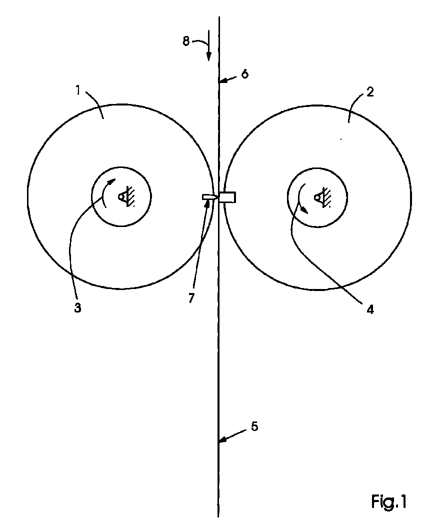
- Fig. 1 shows a cutting cylinder 1 and an associated groove cylinder 2.
- Der Cutting cylinder 1 and grooved cylinder 2 follow the same speed profile in all situations in opposite directions of rotation, as indicated by arrows 3 and 4 is displayed.
- the cutting cylinder 1 is shown in a rotational position in which a Section 5 is cut from a web 6. In this position is the tangential Speed of the knife 7 is equal to the speed of the web 6 as indicated by the arrow 8 is indicated.
- Fig. 2 shows the web 6 moving past the cutting cylinder 1 and the assigned slot cylinder 2 in a non-cutting phase of the cylinder cycle.
- the cutting cylinder 1 one for Speed of the web 6 have different peripheral speeds.
- a first step is the optimal speed of the cutting cylinder 1 and Groove cylinder 2 determined relative to the web 6. Then the algorithm becomes one Cutting cylinder speed profile set, so sections in all lengths be cut off from the web at the optimum cutting cylinder speed can.
- the cutting cylinder speed profile algorithm must therefore be one allow variable path section length.
- the cutting cylinder speed profile algorithm follows the speed of the train.
- a cutting cylinder with a fixed diameter of 156.608 mm used to obtain sections of variable lengths from a web which travels at a constant speed of 15.24 m per second.
- the goal is to cut the web when the knife is the same Speed as the web moves.
- the cutting cylinder must be with rotate an angular velocity of 194.625 radians per second when the cut takes place.
- the nominal track length is the track length that results when the cutting cylinder 1 and the groove cylinder 2 relative to the web with a constant Rotate angular velocity that corresponds to a peripheral speed that is equal to the web speed.
- Fig. 3 is a speed profile of the angular speed of the cutting cylinder 1 for the case 2) previously described.
- the algorithm creates the speed profile for the cutting cylinder shown in FIG. 3.
- the area 9 under the angular velocity curve 10 is equal to 2 ⁇ rad. Based on the exemplary data, this means that the cutting cylinder makes exactly one revolution every 0.041th second and thus cuts sections of 620 mm length at a frequency of 24.581 sections per second from a web while the web is cutting at a constant speed of 15.24 m per second.
- the angular velocity of the cylinder is 40.181 ⁇ cos (154.445 ⁇ t) + 154.445 radians per second ,
- Fig. 4 is a speed profile of the angular speed of the cutting cylinder 1 for the case 3) previously described.
- the area 11 under the angular velocity curve 12 is equal to 2 ⁇ rad. This means that the cutting cylinder makes exactly one revolution every 0.024th second and thus cuts sections of 364 mm in length from a web at a frequency of 41.868 sections per second, while the web is cutting at a constant speed of 15.24 m per second moved.
- the angular velocity is based on the exemplary data -68.44cos (263.065t) + 263.065 radians per second ,
- this can be described Speed profile by controlling a control motor 16, the Cutting cylinder 1 and the associated slot cylinder 2 drives are created.
- the algorithm can be integrated in the control of the control motor.
- Fig. 5 shows an embodiment of the cutting device with a motor 13 for the Drive of the cutting cylinder 1 and a motor 14 for driving the Groove cylinder 2.
- a control device 15 controls the two motors 13, 14.
- Fig. 6 shows an embodiment of the invention with a single motor 16. Der Cutting cylinder 1 and the groove cylinder 2 are mechanical by couplings 17 controlled.
Landscapes
- Life Sciences & Earth Sciences (AREA)
- Forests & Forestry (AREA)
- Engineering & Computer Science (AREA)
- Mechanical Engineering (AREA)
- Folding Of Thin Sheet-Like Materials, Special Discharging Devices, And Others (AREA)
- Perforating, Stamping-Out Or Severing By Means Other Than Cutting (AREA)
- Treatment Of Fiber Materials (AREA)
Abstract
Ein Verfahren zum Schneiden einer Bahn zeichnet sich dadurch aus, dass die Bahn mit
einer im Wesentlichen konstanten Geschwindigkeit bewegt wird, die Bahn in
Bahnabschnitte gewünschter Länge geschnitten wird, wobei sich ein Schneidzylinder
während des Schneidens der Bahn mit einer Schneid-Winkelgeschwindigkeit dreht, die
einer der Geschwindigkeit der Bahn im Wesentlichen angepassten
Umfangsgeschwindigkeit des Schneidzylinders entspricht, und dass die
Winkelgeschwindigkeit des Schneidzylinders nach dem Schneiden in Abhängigkeit von
der gewünschten Länge der Bahnabschnitte geändert wird. Eine Vorrichtung zum
Schneiden einer Bahn zeichnet sich dadurch aus, dass eine Vorrichtung zum Steuern der
Winkelgeschwindigkeit des Schneidzylinders vorgesehen ist, welche den Schneidzylinder
während des Schneidens mit einer Schneid-Winkelgeschwindigkeit dreht, die eine der
Geschwindigkeit der Bahn im Wesentlichen angepassten Umfangsgeschwindigkeit des
Schneidzylinders entspricht, und welche den Schneidzylinder mit einer durchschnittlichen
Winkelgeschwindigkeit dreht, die sich von der Schneid-Winkelgeschwindigkeit
unterscheidet.
Description
Die Erfindung betrifft ein Verfahren zum Schneiden einer Bahn, insbesondere zum
Querschneiden einer Papierbahn in einer Rollenrotationsdruckmaschine, wobei die Bahn
unter Einsatz eines an einem rotierenden Schneidzylinder angeordneten Schneidmessers
in Bahnabschnitte gewünschter Länge geschnitten wird, gemäß dem Oberbegriff von
Anspruch 1.The invention relates to a method for cutting a web, in particular for
Cross cutting a paper web in a web-fed rotary printing press, the web
using a cutting knife arranged on a rotating cutting cylinder
is cut into web sections of the desired length, according to the preamble of
Die Erfindung betrifft weiterhin eine Vorrichtung zum Schneiden einer Bahn,
insbesondere zum Querschneiden einer Papierbahn in einer
Rollenrotationsdruckmaschine, wobei die Bahn unter Einsatz eines an einem rotierenden
Schneidzylinder angeordneten Schneidmessers in Bahnabschnitte gewünschter Länge
geschnitten wird, gemäß dem Oberbegriff von Anspruch 7.The invention further relates to a device for cutting a web,
especially for cross cutting a paper web in a
Web-fed rotary printing machine, the web being used using a rotating one
Cutting cylinder arranged cutting knife in web sections of the desired length
is cut according to the preamble of
In Rollenrotationsdruckmaschinen kann eine Papierbahn, die von einer Rolle zugeführt wird, in einzelne Bahnabschnitte geschnitten werden. Die Papierbahn ist auch als Papierstrang bekannt, insbesondere wenn es sich um einen längsgeschnittenen Abschnitt der Bahn handelt, und die von der Papierbahn quergeschnittenen Bahnabschnitte werden z. B. auch als Bogen oder Signaturen bezeichnet.In web-fed rotary printing presses, a paper web can be fed from a roll will be cut into individual web sections. The paper web is also as Strand of paper known, especially if it is a slit section the web is acting, and the web sections cut by the paper web are e.g. B. also referred to as sheets or signatures.
Es ist bekannt, dass die Produktion von Bahnabschnitten oder Signaturen in unterschiedlichen Längen mit Schneidzylindern erfolgt, die einen festen Durchmesser aufweisen und indem deren Drehgeschwindigkeit relativ zur Geschwindigkeit der Bahn geändert wird. Diese Technik ist wegen des Geschwindigkeitsunterschiedes zwischen der Umfangsgeschwindigkeit des Schneidzylinders und der Geschwindigkeit der Bahn von Nachteil, denn die Umfangsgeschwindigkeit des Schneidzylinders muss gleich oder höher als die Geschwindigkeit der Bahn sein, damit der Bahnabschnitt, welcher dem Schneidmesser nacheilt, sich nicht hinter dem sich langsamer bewegenden Schneidmesser zusammenstaucht. Ist die Umfangsgeschwindigkeit des Schneidzylinders wesentlich höher als die Geschwindigkeit der Bahn, so vermindert sich die Schneid-Qualität.It is known that the production of track sections or signatures in Different lengths are done with cutting cylinders that have a fixed diameter and by their rotational speed relative to the speed of the web will be changed. This technique is because of the speed difference between the Peripheral speed of the cutting cylinder and the speed of the web of Disadvantage, because the peripheral speed of the cutting cylinder must be the same or higher than the speed of the web, so that the web section which corresponds to the Cutting knife lags behind, not behind the slower moving cutting knife collapses. The peripheral speed of the cutting cylinder is essential higher than the speed of the web, the cutting quality is reduced.
Die Transportgeschwindigkeit der Bahnabschnitte nach dem Schneiden hängt ab von der Umfangsgeschwindigkeit der Schneidzylinder. Wenn sich die Umfangsgeschwindigkeit der Schneidzylinder relativ zur Geschwindigkeit der Bahn erhöht, muss sich die Geschwindigkeit der Bahnabschnitte oder Signaturen relativ zur Geschwindigkeit der Bahn ebenfalls erhöhen. Diese Situation macht es erforderlich, dass die Bahnabschnitte oder Signaturen auf die neue, höhere Geschwindigkeit beschleunigt werden müssen. Durch diese Beschleunigung kann es zu Unregelmäßigkeiten in der Position der Bahnabschnitte kommen. Unregelmäßigkeiten in der Bahnabschnittsposition können wiederum die Schneid-Qualität der Bahnabschnitte beeinträchtigen, Probleme mit der Arbeitsweise der Schneidzylinder und letztendlich mit dem Betrieb eines ganzen Druckwerks zur Folge haben.The transport speed of the web sections after cutting depends on the Circumferential speed of the cutting cylinder. If the peripheral speed the cutting cylinder increases relative to the speed of the web, the Speed of the track sections or signatures relative to the speed of the Also increase the path. This situation requires that the track sections or signatures to the new, higher speed must be accelerated. This acceleration can lead to irregularities in the position of the Track sections come. Irregularities in the path section position can in turn affect the cutting quality of the web sections, problems with the Operation of the cutting cylinder and ultimately with the operation of a whole Result in printing unit.
Aus dem Artikel
![]()
![]()
Es ist demnach eine Aufgabe der Erfindung, sowohl ein Verfahren zum Schneiden einer Bahn als auch eine Vorrichtung zum Schneiden einer Bahn zu schaffen, wobei die oben erwähnten Nachteile der bekannten Verfahren und Vorrichtungen dieser Art überwunden werden und es möglich ist, Abschnitte oder Signaturen unterschiedlicher Länge von einer Bahn zu schneiden, ohne dass der Durchmesser des Schneidzylinders und ohne dass die Geschwindigkeit der Abschnitte oder Signaturen geändert werden muss. It is therefore an object of the invention to provide both a method for cutting a Web as well as creating a device for cutting a web, the above mentioned disadvantages of the known methods and devices of this type are overcome and it is possible to have sections or signatures of different lengths of one To cut web without the diameter of the cutting cylinder and without the Speed of sections or signatures needs to be changed.
Diese Aufgabe wird erfindungsgemäß durch die Merkmale von Anspruch 1 sowie die
Merkmale von Anspruch 7 gelöst. Weitere Merkmale der Erfindung sind in den
Unteransprüchen enthalten.This object is achieved by the features of
Zur Lösung der Aufgabe ist gemäß vorliegender Erfindung ein Verfahren zum Schneiden einer Bahn vorgesehen, das sich durch folgende Schritte auszeichnet: Bewegen der Bahn mit einer im Wesentlichen konstanten Geschwindigkeit; Schneiden der Bahn in Bahnabschnitte gewünschter Länge, wobei sich der Schneidzylinder während des Schneidens der Bahn mit einer Schneid-Winkelgeschwindigkeit dreht, die einer der Geschwindigkeit der Bahn im Wesentlichen angepassten Umfangsgeschwindigkeit des Schneidzylinders entspricht; und Ändern der Winkelgeschwindigkeit des Schneidzylinders nach dem Schneiden in Abhängigkeit von der gewünschten Länge der Bahnabschnitte.According to the present invention, a method for cutting is used to achieve the object a track is provided, which is characterized by the following steps: Moving the web at a substantially constant speed; Cutting the web into web sections of the desired length, the Cutting cylinder while cutting the web at a cutting angular speed that rotates one of the speed of the web essentially adjusted circumferential speed of the cutting cylinder corresponds; and Change the angular velocity of the cutting cylinder after cutting in Depends on the desired length of the track sections.
Das beschriebene erfindungsgemäße Verfahren ermöglicht in vorteilhafter Weise eine bewegte Bahn in Abschnitte zu schneiden, deren Längen frei wählbar sind und somit jeder gewünschten Länge entsprechen können, wobei weder Veränderungen an dem zum Schneiden der Bahn vorgesehenen Schneidzylinder nötig sind, noch die Bewegung der Bahn oder der abgeschnittenen Bahnabschnitte verändert werden muss. Während des Schneidens der Bahnabschnitte, also während sich das Schneidmesser mit der Schneid-Winkelgeschwindigkeit dreht, bewegt sich das an dem Schneidzylinder angeordnete Schneidmesser mit einer Geschwindigkeit parallel zu der bewegten Bahn, die dieser im Wesentlichen angepasst ist, wodurch in vorteilhafter Weise ein sehr präziser Schnitt der Bahn erreicht wird und weiterhin ein Aufstauen der Bahn vor oder hinter dem Schneidmesser verhindert wird. Das erfindungsgemäße Verfahren sieht vor, die Winkelgeschwindigkeit des Schneidzylinders nach dem Schneiden in Abhängigkeit von der gewünschten Länge der Bahnabschnitte zu ändern. Hierdurch wird in vorteilhafter Weise erreicht, dass Veränderungen im Bewegungsablauf der Schneidmittel in jener Phase der Drehbewegung des Schneidzylinders erfolgen, in welcher das an dem Schneidzylinder angeordnete Schneidmesser nicht in Kontakt mit der bewegten Bahn ist, wodurch jegliche störende Einflüsse auf den Schneidvorgang verhindert werden. The method according to the invention described advantageously enables to cut moving web into sections, the lengths of which are freely selectable and thus can correspond to any desired length, with neither changes to the to Cutting the intended cutting cylinder are still necessary, the movement of the Path or the cut path sections must be changed. During the Cutting the web sections, i.e. while the cutting knife is moving at the cutting angular velocity rotates, that arranged on the cutting cylinder moves Cutting knife at a speed parallel to the moving path that this in the Is essentially adapted, thereby advantageously a very precise cut of the The web is reached and the web continues to be stowed in front of or behind the Cutting knife is prevented. The method according to the invention provides that Angular speed of the cutting cylinder after cutting depending on change the desired length of the track sections. This will be more advantageous Way that changes in the movement of the cutting means in that Phase of the rotary movement of the cutting cylinder take place, in which the Cutting cylinder arranged cutting knife is not in contact with the moving web, which prevents any disruptive influences on the cutting process.
Gemäß einer weiteren Ausgestaltung des erfindungsgemäßen Verfahrens kann das Ändern der Winkelgeschwindigkeit des Schneidzylinders in der Weise erfolgen, dass sich der Schneidzylinder mit einer durchschnittlichen Winkelgeschwindigkeit dreht, die einer Umfangsgeschwindigkeit des Schneidzylinders entspricht, welche höher oder niedriger als die Geschwindigkeit der Bahn ist. Bei einer höheren durchschnittlichen Winkelgeschwindigkeit werden kürzere Abschnitte von der Bahn abgeschnitten, während bei einer niedrigeren Winkelgeschwindigkeit längere Abschnitte von der Bahn abgeschnitten werden.According to a further embodiment of the method according to the invention, the Changing the angular velocity of the cutting cylinder is done in such a way that the cutting cylinder rotates at an average angular speed that one Circumferential speed of the cutting cylinder corresponds to which is higher or lower than the speed of the web is. At a higher average Angular velocity will cut off shorter sections of the web while longer sections of the web at a lower angular velocity be cut off.
Gemäß einer weiteren erfindungsgemäßen Verfahrensweise kann die Schneid-Winkelgeschwindigkeit
mit der folgenden Berechnungsformel bestimmt werden:
Es kann ebenfalls vorgesehen sein, das erfindungsgemäße Verfahren in der Weise
auszuführen, dass das Ändern der Winkelgeschwindigkeit des Schneidzylinders nach
folgender Berechnungsformel gesteuert wird:
Gemäß einer weiteren Ausführungsform des erfindungsgemäßen Verfahrens kann ein Nutenzylinder bereitgestellt werden, der sich synchron mit dem Schneidzylinder dreht. Durch den dem Schneidzylinder zugeordneten Nutenzylinder wird das an dem Schneidzylinder angeordnete Schneidmesser während des Schneidens der Bahn unterstützt und geführt, was in vorteilhafter Weise einen präzisen Schnitt der Bahn erlaubt. Weiterhin kann der Nutenzylinder eine Schneidleiste enthalten, welche mit dem an dem Schneidzylinder angeordneten Schneidmesser während des Schneidens zusammenwirkt, und welche zusätzlich das Schneidergebnis in positiver Weise beeinflusst, während es gleichzeitig ein Abnutzen des Schneidmessers weitestgehend verhindert. According to a further embodiment of the method according to the invention, a Groove cylinder are provided, which rotates synchronously with the cutting cylinder. The groove cylinder assigned to the cutting cylinder makes this possible on the Cutting cylinder arranged cutting knife during cutting the web supported and guided, which is advantageously a precise cut of the web allowed. Furthermore, the groove cylinder can contain a cutting bar, which with the cutting blades arranged on the cutting cylinder during the cutting cooperates, and which additionally the cutting result in a positive way influenced, while at the same time the cutting knife wears out as much as possible prevented.
Ferner ist als Lösung der Aufgabe gemäß vorliegender Erfindung eine Vorrichtung zum Schneiden einer Bahn vorgesehen, die sich durch folgende Merkmale auszeichnet: eine Einrichtung zum Steuern der Winkelgeschwindigkeit des Schneidzylinders, welche den Schneidzylinder während des Schneidens mit einer Schneid-Winkelgeschwindigkeit dreht, die eine der Geschwindigkeit der Bahn im Wesentlichen angepassten Umfangsgeschwindigkeit des Schneidzylinders entspricht, und welche den Schneidzylinder mit einer durchschnittlichen Winkelgeschwindigkeit dreht, die sich von der Schneid-Winkelgeschwindigkeit unterscheidet. Die beschriebene erfindungsgemäße Vorrichtung umfasst somit eine Einrichtung zum Steuern der Winkelgeschwindigkeit des Schneidzylinders, mit welcher es in vorteilhafter Weise möglich wird, Bahnabschnitte gewünschter Länge von einer bewegten Bahn abzuschneiden, ohne Veränderungen an den Schneidmitteln vornehmen zu müssen oder die Geschwindigkeit der bewegten Bahn bzw. der abgeschnittenen Bahnabschnitte verändern zu müssen. Die bewegte Bahn sowie die geschnittenen Bahnabschnitte können beim Schneiden mit der erfindungsgemäßen Vorrichtung unverändert weiter bewegt werden, wodurch Beschädigungen, Verformungen und auch ein Aufstauen der bewegten Bahn wie auch der geschnittenen Bahnabschnitte verhindert werden können.Furthermore, as a solution to the problem according to the present invention, a device for Cutting a path is provided, which is characterized by the following features: means for controlling the angular velocity of the cutting cylinder, which the cutting cylinder during cutting at a cutting angular speed rotates, which is essentially adapted to the speed of the web Circumferential speed of the cutting cylinder corresponds, and which the Cutting cylinder rotates at an average angular speed that varies from the cutting angular velocity differs. The described invention The device thus comprises a device for controlling the angular velocity of the Cutting cylinder, with which it is advantageously possible, web sections Cut the desired length from a moving web without making any changes the cutting means or the speed of the moving web or to change the cut sections of the web. The moving train as well the cut web sections can be cut with the invention Device can be moved on unchanged, causing damage, Deformations and also a build-up of the moving web as well as the cut one Path sections can be prevented.
Gemäß einer weiteren Ausführungsform der Erfindung kann die Schneid-Winkelgeschwindigkeit
durch die Steuerungseinrichtung nach folgender
Berechnungsformel bestimmt werden:
Gemäß einer weiteren Ausführungsform der Erfindung kann die Winkelgeschwindigkeit
des Schneidzylinders durch die Steuerungseinrichtung nach folgender Berechnungsformel
bestimmt werden:
Gemäß einer weiteren Ausführungsform der Erfindung kann die Schneidvorrichtung einen dem Schneidzylinder zugeordneten Nutenzylinder umfassen, der sich synchron mit dem Schneidzylinder dreht. Durch das Zusammenwirken des an dem Schneidzylinder angeordneten Schneidmessers mit dem zugeordneten Nutenzylinder, insbesondere mit einer in dem Nutenzylinder vorgesehenen Schneidleiste, wird eine Stabilisierung des Schneidmessers während des Schneidens erreicht und somit der Schnitt präzise und kontrolliert durchgeführt. Weiterhin schützt die im Nutenzylinder angeordnete Schneidleiste das Schneidmesser in vorteilhafter Weise vor einer zu schnellen Abnutzung.According to a further embodiment of the invention, the cutting device comprise a grooved cylinder assigned to the cutting cylinder and synchronized with it the cutting cylinder rotates. By the interaction of the on the cutting cylinder arranged cutting knife with the associated groove cylinder, in particular with a cutting bar provided in the groove cylinder stabilizes the Cutting knife reached during cutting and thus the cut precise and carried out in a controlled manner. Furthermore, the one in the slot cylinder protects Cutting bar the cutting knife in an advantageous manner before too fast Wear.
Gemäß einer anderen Ausführungsform der erfindungsgemäßen Vorrichtung kann die Schneidvorrichtung einen Regelmotor für den Antrieb des Schneidzylinders und des Nutenzylinders umfassen, wobei die Steuerungseinrichtung den Regelmotor steuert. Durch die Verwendung eines Regelmotors, welcher sowohl den Schneidzylinder als auch den Nutenzylinder antreibt, ist die Steuerung dieser beiden Zylinder, z. B. gemäß der oben dargestellten Formel zur Berechnung der Winkelgeschwindigkeit des Schneidzylinders in Abhängigkeit von der Zeit, in einfacher Weise durch eine Steuerungseinrichtung durchführbar.According to another embodiment of the device according to the invention, the Cutting device a control motor for driving the cutting cylinder and the Groove cylinders include, wherein the control device controls the control motor. By using a control motor, which both the cutting cylinder and drives the slot cylinder, the control of these two cylinders, for. B. according to the Formula shown above for calculating the angular velocity of the Cutting cylinder depending on the time, in a simple manner through a Control device feasible.
Es kann weiterhin vorgesehen sein, dass der Regelmotor jeden einzelnen der beiden Zylinder über eine Kupplung antreibt.It can also be provided that the control motor each of the two Drives cylinder via a clutch.
Ferner kann es vorgesehen sein, die erfindungsgemäße Vorrichtung derart auszugestalten, dass wenigstens einer der beiden Zylinder mit einem mechanischen Getriebe angetrieben wird, welches durch seine Konstruktion eine Änderung der Winkelgeschwindigkeit des Zylinders, z. B. gemäß der oben dargestellten Berechnungsformel für die Winkelgeschwindigkeit des Schneidzylinders, bewirkt.Furthermore, the device according to the invention can be provided in this way to design that at least one of the two cylinders with a mechanical Gearbox is driven, which by its construction a change of Angular velocity of the cylinder, e.g. B. according to the above Calculation formula for the angular velocity of the cutting cylinder.
Es kann weiterhin vorgesehen sein, dass die erfindungsgemäße Schneidvorrichtung ferner eine mechanische Kopplung zur Verbindung des Schneidzylinders mit dem Nutenzylinder umfasst. Dabei kann es auch vorgesehen sein, dass der Regelmotor einen der beiden Zylinder direkt antreibt, während der andere der beiden Zylinder über die mechanische Kopplung angetrieben wird. Durch die Kopplung der beiden Zylinder mit einer mechanischen Kopplung ist in vorteilhafter Weise eine sehr einfache Anpassung der Winkelgeschwindigkeiten der beiden Zylinder möglich. Zusätzlich wird durch die mechanische Kopplung die exakte Ausrichtung des an dem Schneidzylinder angeordneten Schneidmessers auf den Nutenzylinder, insbesondere auf eine an dem Nutenzylinder angeordnete Schneidleiste, gewährleistet.It can further be provided that the cutting device according to the invention is furthermore a mechanical coupling for connecting the cutting cylinder to the grooved cylinder includes. It can also be provided that the control motor is one of the two Cylinder drives directly while the other of the two cylinders is mechanical Coupling is driven. By coupling the two cylinders with one mechanical coupling is advantageously a very simple adjustment of the Angular speeds of the two cylinders possible. In addition, the mechanical coupling the exact alignment of the arranged on the cutting cylinder Cutting knife on the slot cylinder, in particular on one on the slot cylinder arranged cutting bar, guaranteed.
Gemäß einer weiteren Ausführungsform der Erfindung kann die Schneidvorrichtung einen ersten Regelmotor für den Antrieb des Schneidzylinders und einen zweiten Regelmotor für den Antrieb des Nutenzylinders umfassen, wobei die Steuerungseinrichtung beide Motoren steuert. Es kann jedoch auch vorgesehen sein, dass jeder Regelmotor durch eine eigene Steuerungseinrichtung gesteuert wird. According to a further embodiment of the invention, the cutting device a first control motor for driving the cutting cylinder and a second Control motor for driving the slot cylinder include, the Control device controls both motors. However, it can also be provided that each control motor is controlled by its own control device.
Es kann weiterhin vorgesehen sein, eine Druckmaschine oder einen Falzapparat mit einer erfindungsgemäßen Vorrichtung zum Schneiden einer Bahn auszustatten.It can also be provided that a printing press or a folder with a equip device according to the invention for cutting a web.
Weitere charakteristische Merkmale der Erfindung sind in den beigefügten Ansprüchen dargelegt.Further characteristic features of the invention are in the appended claims spelled out.
Die Erfindung wird in der folgenden Beschreibung bevorzugter Ausführungsformen im Zusammenhang mit den beigefügten, nachstehend aufgeführten Zeichnungen näher erläutert.The invention is illustrated in the following description of preferred embodiments in the Connection with the accompanying drawings listed below explained.
Es zeigen:
- Fig. 1
- einen schematischen Seitenaufriss einer Schneidvorrichtung während eines Schneidvorgangs;
- Fig. 2
- einen schematischen Seitenaufriss der Schneidvorrichtung in einer Nicht-Schneide-Phase;
- Fig. 3 und 4
- Geschwindigkeitsprofile eines Schneidzylinders zur Produktion von Bahnabschnitten in unterschiedlichen Längen;
- Fig. 5
- einen schematischen Seitenaufriss der erfindungsgemäßen Schneidvorrichtung mit einem Motor für jeden Zylinder; und
- Fig. 6
- einen schematischen Seitenaufriss der erfindungsgemäßen Schneidvorrichtung mit einer mechanischen Kopplung zur Steuerung der Zylinder.
- Fig. 1
- a schematic side elevation of a cutting device during a cutting operation;
- Fig. 2
- a schematic side elevation of the cutting device in a non-cutting phase;
- 3 and 4
- Speed profiles of a cutting cylinder for the production of web sections in different lengths;
- Fig. 5
- a schematic side elevation of the cutting device according to the invention with a motor for each cylinder; and
- Fig. 6
- a schematic side elevation of the cutting device according to the invention with a mechanical coupling for controlling the cylinder.
Fig. 1 zeigt einen Schneidzylinder 1 und einen zugeordneten Nutenzylinder 2. Der
Schneidzylinder 1 und der Nutenzylinder 2 folgen dem gleichen Geschwindigkeitsprofil
in allen Situationen in gegenläufigen Drehrichtungen, wie dies durch die Pfeile 3 und 4
angezeigt ist. Der Schneidzylinder 1 ist in einer Drehposition gezeigt, in der ein
Abschnitt 5 von einer Bahn 6 abgeschnitten wird. In dieser Position ist die tangentiale
Geschwindigkeit des Messers 7 gleich der Geschwindigkeit der Bahn 6, wie dies durch
den Pfeil 8 angedeutet ist.Fig. 1 shows a
Fig. 2 zeigt die sich am Schneidzylinder 1 vorbei bewegende Bahn 6 und den
zugeordneten Nutenzylinder 2 in einer Nicht-Schneide-Phase des Zylinderzyklus. In
dieser Nicht-Schneide-Phase des Zylinderzyklus kann der Schneidzylinder 1 eine zur
Geschwindigkeit der Bahn 6 unterschiedliche Umfangsgeschwindigkeit haben.Fig. 2 shows the
Die operativen Schritte der Schneidvorrichtung sind im Folgenden näher beschrieben. In
einem ersten Schritt wird die optimale Geschwindigkeit des Schneidzylinders 1 und des
Nutenzylinders 2 relativ zur Bahn 6 bestimmt. Dann wird der Algorithmus eines
Schneidzylinder-Geschwindigkeitsprofils festgelegt, sodass Abschnitte in allen Längen
bei optimaler Schneidzylindergeschwindigkeit von der Bahn abgeschnitten werden
können. Der Schneidzylinder-Geschwindigkeitsprofil-Algorithmus muss also eine
variable Bahnabschnittslänge ermöglichen. Im übrigen folgt der Schneidzylinder-Geschwindigkeitsprofil-Algorithmus
der Geschwindigkeit der Bahn.The operational steps of the cutting device are described in more detail below. In
a first step is the optimal speed of the
Diese Strategie des Abschneidens von Abschnitten in variablen Längen von einer Bahn 6,
die sich mit konstanter Geschwindigkeit fortbewegt, kann in drei Kategorien eingeteilt
werden.
Im folgenden Beispiel wird ein Schneidzylinder mit einem festen Durchmesser von 156,608 mm verwendet, um Abschnitte in variablen Längen von einer Bahn zu erhalten, die sich mit einer konstanten Geschwindigkeit von 15,24 m pro Sekunde fortbewegt.In the following example a cutting cylinder with a fixed diameter of 156.608 mm used to obtain sections of variable lengths from a web which travels at a constant speed of 15.24 m per second.
Das Ziel ist, die Bahn zu schneiden, wenn sich das Messer mit der gleichen Geschwindigkeit wie die Bahn fortbewegt. Hierzu muss sich der Schneidzylinder mit einer Winkelgeschwindigkeit von 194,625 Radiant pro Sekunde drehen, wenn der Schnitt stattfindet.The goal is to cut the web when the knife is the same Speed as the web moves. For this, the cutting cylinder must be with rotate an angular velocity of 194.625 radians per second when the cut takes place.
Es werden Abschnitte in drei verschiedenen Längen von der Bahn abgeschnitten. Da sich die Bahn mit einer konstanten Geschwindigkeit fortbewegt, hängt die Anzahl der pro Sekunde produzierten Bahnabschnitte von der Länge der jeweiligen Bahnabschnitte ab. Je kürzer der Bahnabschnitt ist, umso mehr Bahnabschnitte werden pro Sekunde produziert.
- Fall 1)
- Bahnabschnittslänge = 492 mm
Bahnabschnitte pro Sekunde = 30,976
- Case 1)
- Track section length = 492 mm
Track sections per second = 30.976
Der Schneidzylinderumfang beträgt 492 mm, sodass sich in diesem Fall der Schneidzylinder mit einer konstanten Winkelgeschwindigkeit von 194,625 Radiant pro Sekunde dreht.
- Fall 2)
- Bahnabschnittslänge = 620 mm
Bahnabschnitte pro Sekunde = 24,581
- Case 2)
- Track section length = 620 mm
Track sections per second = 24.581
In diesem Fall ändert sich die Geschwindigkeit des Schneidzylinders während seiner
Umdrehung. Das Geschwindigkeitsprofil besitzt die folgenden Merkmale:
- Fall 3)
- Bahnabschnittslänge = 364 mm
Bahnabschnitte pro Sekunde = 41,868
- Case 3)
- Track section length = 364 mm
Track sections per second = 41.868
In diesem Fall ändert sich die Geschwindigkeit des Schneidzylinders während seiner
Umdrehung. Das Geschwindigkeitsprofil besitzt die folgenden Merkmale:
Die allgemeine Berechnungsformel für die Steuerung des Schneidzylinders ist folgende:
Die nominale Bahnabschnittslänge ist die Bahnabschnittslänge, die sich ergibt, wenn sich
der Schneidzylinder 1 und der Nutenzylinder 2 relativ zur Bahn mit einer konstanten
Winkelgeschwindigkeit drehen, welche einer Umfangsgeschwindigkeit entspricht, die
gleich der Bahngeschwindigkeit ist.The nominal track length is the track length that results when
the
Fig. 3 ist ein Geschwindigkeitsprofil der Winkelgeschwindigkeit des Schneidzylinders 1
für den vorher beschriebenen Fall 2). Für dieses spezifische Beispiel wird mittels des
Algorithmus das Geschwindigkeitsprofil für den in Fig. 3 gezeigten Schneidzylinder
erstellt. Die Fläche 9 unter der Winkelgeschwindigkeitskurve 10 ist gleich 2π rad. Auf
der Basis der beispielhaften Daten bedeutet dies, dass der Schneidzylinder in jeder
0,041sten Sekunde genau eine Umdrehung macht und somit Abschnitte von 620 mm
Länge bei einer Frequenz von 24,581 Abschnitten pro Sekunde von einer Bahn
abschneidet, während sich die Bahn mit einer konstanten Geschwindigkeit von 15,24 m
pro Sekunde fortbewegt. Die Winkelgeschwindigkeit des Zylinders beträgt
Fig. 4 ist ein Geschwindigkeitsprofil der Winkelgeschwindigkeit des Schneidzylinders 1
für den vorher beschriebenen Fall 3). Die Fläche 11 unter der
Winkelgeschwindigkeitskurve 12 ist gleich 2π rad. Dieses bedeutet, dass der
Schneidzylinder in jeder 0,024sten Sekunde genau eine Umdrehung macht und somit
Abschnitte von 364 mm Länge bei einer Frequenz von 41,868 Abschnitten pro Sekunde
von einer Bahn abschneidet, während sich die Bahn mit einer konstanten
Geschwindigkeit von 15,24 m pro Sekunde fortbewegt. Auf der Basis der beispielhaften
Daten ist die Winkelgeschwindigkeit
In einer bevorzugten Ausführungsform der Erfindung kann das beschriebene
Geschwindigkeitsprofil durch Steuerung eines Regelmotors 16, der den
Schneidzylinder 1 und den zugeordneten Nutenzylinder 2 antreibt, erstellt werden. Der
Algorithmus kann in die Steuerung des Regelmotors integriert sein.In a preferred embodiment of the invention, this can be described
Speed profile by controlling a
Um spezifischen Anforderungen zu genügen, können zur Erstellung eines
Geschwindigkeitsprofils andere Algorithmen als die vorangehend beschriebenen
verwendet werden. Es kann jedes Geschwindigkeitsprofil angewandt werden, das den
Schneidzylinder 1 befähigt, die Bahn 6 mit optimaler Geschwindigkeit zu schneiden und
die Bahnabschnitte 5 in der gewünschten Länge und Frequenz zu produzieren. Alternativ
kann die Geschwindigkeit des Schneidzylinders 1 in einer anderen als der vorhergehend
beschriebenen Weise gesteuert werden.To meet specific requirements, you can create a
Speed profile algorithms other than those described above
be used. Any speed profile that matches the
Fig. 5 zeigt eine Ausführungsform der Schneidvorrichtung mit einem Motor 13 für den
Antrieb des Schneidzylinders 1 und einem Motor 14 für den Antrieb des
Nutenzylinders 2. Eine Steuerungseinrichtung 15 steuert die beiden Motoren 13, 14.Fig. 5 shows an embodiment of the cutting device with a
Fig. 6 zeigt eine Ausführungsform der Erfindung mit einem einzigen Motor 16. Der
Schneidzylinder 1 und der Nutenzylinder 2 werden durch Kopplungen 17 mechanisch
gesteuert. Fig. 6 shows an embodiment of the invention with a
- 11
- SchneidzylinderCutting cylinder
- 22nd
- NutenzylinderGroove cylinder
- 33rd
- Pfeil zur Darstellung der DrehrichtungArrow to show the direction of rotation
- 44th
- Pfeil zur Darstellung der DrehrichtungArrow to show the direction of rotation
- 55
- Bahnabschnitt / SignaturTrack section / signature
- 66
- Bahn / StrangWeb / strand
- 77
- Messerknife
- 88th
- Pfeil zur Darstellung der Bewegungsrichtung der BahnArrow to show the direction of movement of the web
- 99
- Fläche unter der WinkelgeschwindigkeitskurveArea under the angular velocity curve
- 1010th
- WinkelgeschwindigkeitskurveAngular velocity curve
- 1111
- Fläche unter der WinkelgeschwindigkeitskurveArea under the angular velocity curve
- 1212th
- WinkelgeschwindigkeitskurveAngular velocity curve
- 1313
- RegelmotorControl motor
- 1414
- RegelmotorControl motor
- 1515
- SteuerungseinrichtungControl device
- 1616
- RegelmotorControl motor
- 1717th
- KopplungenCouplings
Claims (15)
dadurch gekennzeichnet,
dass das Ändern der Winkelgeschwindigkeit des Schneidzylinders derart erfolgt, dass sich der Schneidzylinder mit einer durchschnittlichen Winkelgeschwindigkeit dreht, die einer Umfangsgeschwindigkeit des Schneidzylinders entspricht, welche höher als die Geschwindigkeit der Bahn ist.Method according to claim 1,
characterized,
that the changing of the angular speed of the cutting cylinder is such that the cutting cylinder rotates at an average angular speed which corresponds to a peripheral speed of the cutting cylinder which is higher than the speed of the web.
dadurch gekennzeichnet,
dass das Ändern der Winkelgeschwindigkeit des Schneidzylinders derart erfolgt, dass sich der Schneidzylinder mit einer durchschnittlichen Winkelgeschwindigkeit dreht, die einer Umfangsgeschwindigkeit des Schneidzylinders entspricht, welche niedriger als die Geschwindigkeit der Bahn ist.Method according to claim 1,
characterized,
that the changing of the angular speed of the cutting cylinder is such that the cutting cylinder rotates at an average angular speed which corresponds to a peripheral speed of the cutting cylinder which is lower than the speed of the web.
dadurch gekennzeichnet,
dass die Schneid-Winkelgeschwindigkeit mit folgender Berechnungsformel bestimmt wird:
characterized,
that the cutting angular velocity is determined using the following calculation formula:
dadurch gekennzeichnet,
dass das Ändern der Winkelgeschwindigkeit des Schneidzylinders (1) nach folgender Berechnungsformel gesteuert wird:
characterized,
that the change in the angular velocity of the cutting cylinder (1) is controlled according to the following calculation formula:
dadurch gekennzeichnet,
dass ein Nutenzylinder (2) bereitgestellt wird, der sich synchron mit dem Schneidzylinder (1) dreht.Method according to one of the preceding claims,
characterized,
that a groove cylinder (2) is provided which rotates synchronously with the cutting cylinder (1).
dadurch gekennzeichnet,
dass eine Einrichtung zum Steuern der Winkelgeschwindigkeit des Schneidzylinders vorgesehen ist, welche den Schneidzylinder während des Schneidens mit einer Schneid-Winkelgeschwindigkeit dreht, die eine der Geschwindigkeit der Bahn im Wesentlichen angepassten Umfangsgeschwindigkeit des Schneidzylinders entspricht, und welche den Schneidzylinder mit einer durchschnittlichen Winkelgeschwindigkeit dreht, die sich von der Schneid-Winkelgeschwindigkeit unterscheidet.Device for cutting a web, in particular for cross-cutting a paper web in a web-fed rotary printing press, the web being cut into web sections of the desired length using a cutting knife arranged on a rotating cutting cylinder,
characterized,
that means are provided for controlling the angular velocity of the cutting cylinder, which rotates the cutting cylinder during cutting at a cutting angular velocity which corresponds to a peripheral speed of the cutting cylinder which is substantially adapted to the speed of the path, and which rotates the cutting cylinder at an average angular velocity which differs from the cutting angular velocity.
dadurch gekennzeichnet,
dass die Einrichtung zum Steuern (15) die Schneid-Winkelgeschwindigkeit mit folgender Berechnungsformel bestimmt:
characterized,
that the control device (15) determines the cutting angular velocity using the following calculation formula:
dadurch gekennzeichnet,
dass die Einrichtung zum Steuern (15) die Winkelgeschwindigkeit des Schneidzylinders mit folgender Berechnungsformel bestimmt:
characterized,
that the control device (15) determines the angular velocity of the cutting cylinder using the following calculation formula:
dadurch gekennzeichnet,
dass ferner ein Nutenzylinder (2)vorgesehen ist, der dem Schneidzylinder (1) zugeordnet ist und sich synchron mit diesem dreht.Device according to one of claims 7 to 9,
characterized,
that a groove cylinder (2) is also provided, which is assigned to the cutting cylinder (1) and rotates synchronously with it.
dadurch gekennzeichnet,
dass ferner ein Regelmotor (16) für den Antrieb des Schneidzylinders (1) und des Nutenzylinders (2) vorgesehen ist und dass die Einrichtung zum Steuern (15) den Regelmotor (16) steuert.Device according to one of claims 7 to 10,
characterized,
that a control motor (16) for driving the cutting cylinder (1) and the grooved cylinder (2) is also provided and that the control device (15) controls the control motor (16).
dadurch gekennzeichnet,
dass ferner eine mechanische Kopplung (17) vorgesehen ist, die den Schneidzylinder (1) und den Nutenzylinder (2) verbindet.Apparatus according to claim 11
characterized,
that a mechanical coupling (17) is also provided, which connects the cutting cylinder (1) and the grooved cylinder (2).
dadurch gekennzeichnet,
dass ferner ein erster Regelmotor (13) für den Antrieb des Schneidzylinders (1) und ein zweiter Regelmotor (14) für den Antrieb des Nutenzylinders (2) vorgesehen sind und dass die Einrichtung zum Steuern (15) den ersten und den zweiten Regelmotor (13, 14) steuert.Device according to one of claims 7 to 10
characterized,
that a first control motor (13) for driving the cutting cylinder (1) and a second control motor (14) for driving the grooved cylinder (2) are provided and that the device for controlling (15) the first and second control motors (13 , 14) controls.
gekennzeichnet durch eine Vorrichtung zum Schneiden einer Bahn gemäß einem der Ansprüche 7 bis 13.Printing press,
characterized by a device for cutting a web according to one of claims 7 to 13.
gekennzeichnet durch eine Vorrichtung zum Schneiden einer Bahn gemäß einem der Ansprüche 7 bis 13.Folder,
characterized by a device for cutting a web according to one of claims 7 to 13.
Applications Claiming Priority (2)
| Application Number | Priority Date | Filing Date | Title |
|---|---|---|---|
| US352253 | 1999-07-13 | ||
| US09/352,253 US6360640B1 (en) | 1999-07-13 | 1999-07-13 | Variable velocity cutting cylinders |
Publications (2)
| Publication Number | Publication Date |
|---|---|
| EP1069061A2 true EP1069061A2 (en) | 2001-01-17 |
| EP1069061A3 EP1069061A3 (en) | 2002-07-17 |
Family
ID=23384384
Family Applications (1)
| Application Number | Title | Priority Date | Filing Date |
|---|---|---|---|
| EP00111977A Withdrawn EP1069061A3 (en) | 1999-07-13 | 2000-06-19 | Method and device for cutting a web |
Country Status (4)
| Country | Link |
|---|---|
| US (1) | US6360640B1 (en) |
| EP (1) | EP1069061A3 (en) |
| JP (1) | JP2001039615A (en) |
| DE (1) | DE10030055A1 (en) |
Cited By (6)
| Publication number | Priority date | Publication date | Assignee | Title |
|---|---|---|---|---|
| EP1864768A1 (en) | 2006-06-05 | 2007-12-12 | Fameccanica.Data S.p.A. | Cutting device, for instance for producing sanitary products, and corresponding methods of operation |
| WO2008015588A3 (en) * | 2006-08-03 | 2008-04-17 | Kimberly Clark Co | Variable sheet-length perforation or cutting system |
| DE102007034834A1 (en) * | 2007-07-26 | 2009-01-29 | Robert Bosch Gmbh | Method and device for optimizing cross-processing operations |
| EP1839858A3 (en) * | 2006-03-28 | 2011-03-30 | manroland AG | Folding apparatus of a printing press and method for operating the same |
| CN106626728A (en) * | 2016-12-21 | 2017-05-10 | 安徽庆丰余防伪科技有限公司 | Printing device with automatic cutting and edge trimming functions |
| US10471619B2 (en) | 2016-01-23 | 2019-11-12 | John Bean Technologies Corporation | Blade portioner calibration |
Families Citing this family (29)
| Publication number | Priority date | Publication date | Assignee | Title |
|---|---|---|---|---|
| US6684746B2 (en) * | 1999-12-02 | 2004-02-03 | Heidelberger Druckmaschinen Ag | Variable-length cut-off folder and method |
| KR100401629B1 (en) * | 2001-03-26 | 2003-10-17 | 현대자동차주식회사 | A equipment for removing string from front whather strip |
| JP4712756B2 (en) * | 2001-08-29 | 2011-06-29 | 株式会社瑞光 | Manufacturing method of article |
| JP4712757B2 (en) * | 2001-08-29 | 2011-06-29 | 株式会社瑞光 | Method for manufacturing worn article |
| JP4495393B2 (en) * | 2001-08-29 | 2010-07-07 | 株式会社瑞光 | Manufacturing method of article |
| US6845698B2 (en) * | 2002-02-25 | 2005-01-25 | Ppg Industries Ohio, Inc. | Systems and methods for severing elongated material |
| DE10213978A1 (en) * | 2002-03-28 | 2003-10-09 | Roland Man Druckmasch | Process for cross cutting a running web |
| FR2840558B1 (en) * | 2002-06-07 | 2004-10-01 | Rapidex Sm | SHEET PROCESSING MACHINE WITH CUTTINGS OR CROSS-FOLD FOLDING HAVING THEIR DIRECTION OF FORWARD |
| DE10245322A1 (en) * | 2002-09-27 | 2004-04-08 | Man Roland Druckmaschinen Ag | Process for cross cutting a web |
| US7044902B2 (en) * | 2003-12-09 | 2006-05-16 | Quad/Tech, Inc. | Printing press folder and folder components |
| DE10357795A1 (en) * | 2003-12-10 | 2005-07-14 | WINKLER + DüNNEBIER AG | Use of a device for cutting a material web and apparatus for use in the context of use |
| DE102005002683A1 (en) * | 2005-01-20 | 2006-08-03 | Man Roland Druckmaschinen Ag | Folding appliance for rotary roller press machine has separate drive assigned to cutting knife cylinder whereby drive is operated in collection area of folding appliance for provision of collecting copies of different non-uniform arc length |
| US8002257B2 (en) * | 2009-02-06 | 2011-08-23 | Goss International Americas, Inc. | Web conversion and collating apparatus and method |
| US8020847B2 (en) * | 2009-02-06 | 2011-09-20 | Goss International Americas, Inc. | Multiple delivery web conversion apparatus and method of producing and delivering variable printed products |
| US7963515B2 (en) * | 2009-02-06 | 2011-06-21 | Goss International Americas, Inc. | Adjustable delivery web conversion apparatus and method |
| US8020845B2 (en) * | 2009-02-06 | 2011-09-20 | Goss International Americas, Inc. | Single level web conversion apparatus and method |
| DE102009013850A1 (en) * | 2009-03-18 | 2010-09-23 | Robert Bosch Gmbh | Method for operating a processing roller |
| DE102009061056A1 (en) * | 2009-08-28 | 2011-06-16 | Manroland Ag | Format variable web press |
| IT1397984B1 (en) * | 2010-02-08 | 2013-02-04 | Tecnau Srl | CROSS-DRILLING DRIVING EQUIPMENT FOR CONTINUOUS MODULES IN MOTION |
| US8113411B2 (en) * | 2010-03-30 | 2012-02-14 | Flextronics Ap, Llc | Universal radio frequency shield removal |
| US20130269493A1 (en) * | 2012-04-17 | 2013-10-17 | Goss International Americas, Inc. | Variable cutoff in a cutter folder |
| US20140121091A1 (en) * | 2012-10-26 | 2014-05-01 | Kabushiki Kaisha Tokyo Kikai Seisakusho | Variable cutoff folding device and printer comprising variable cutoff folding device |
| US9731489B2 (en) | 2013-05-29 | 2017-08-15 | H.B. Fuller Company | Material application system |
| US9579814B2 (en) * | 2014-04-22 | 2017-02-28 | Lexmark International, Inc. | Motor control system and method for a rotary hole punch system |
| WO2016059298A1 (en) * | 2014-10-15 | 2016-04-21 | Raute Oyj | Control of clipping |
| EP3466382B1 (en) * | 2016-06-06 | 2020-07-01 | Unicharm Corporation | Production method and production device for continuous sheet composite for absorbent article |
| WO2019173320A1 (en) | 2018-03-05 | 2019-09-12 | H.B. Fuller Company | Web material application systems and methods |
| JP7450918B2 (en) * | 2019-12-16 | 2024-03-18 | 株式会社名南製作所 | Veneer cutting and sorting equipment |
| IT202300025977A1 (en) * | 2023-12-05 | 2025-06-05 | Fameccanica Data Spa | APPARATUS FOR THE TREATMENT OF CONTINUOUS MOVING SHEETS AND MACHINE COMPRISING SUCH APPARATUS |
Family Cites Families (22)
| Publication number | Priority date | Publication date | Assignee | Title |
|---|---|---|---|---|
| US2947184A (en) * | 1956-10-19 | 1960-08-02 | Youngstown Sheet And Tube Co | Variable speed transmission |
| NL287402A (en) * | 1962-01-03 | 1900-01-01 | ||
| US3614572A (en) * | 1970-03-16 | 1971-10-19 | Gen Electric | Automatic control system for crop shear |
| US3832926A (en) * | 1973-10-29 | 1974-09-03 | Koppers Co Inc | Apparatus for accurate die-cutting |
| JPS5315684A (en) * | 1976-07-29 | 1978-02-13 | Fuji Photo Film Co Ltd | Device for cutting web |
| JPS5380089A (en) * | 1976-12-23 | 1978-07-15 | Fuji Photo Film Co Ltd | Cutting apparatus for web |
| DE2749174A1 (en) * | 1977-11-03 | 1979-05-10 | Hauni Werke Koerber & Co Kg | ARRANGEMENT FOR CONTROLLING THE ROTATING CUTTING ROLLER OF A CROSS-CUTTING DEVICE |
| DE2840377C2 (en) * | 1978-09-16 | 1983-11-10 | Jagenberg-Werke AG, 4000 Düsseldorf | Device for setting the format length on a cross cutter for material webs |
| JPS56119311A (en) * | 1980-02-20 | 1981-09-18 | Mitsubishi Heavy Ind Ltd | Drum shear |
| US4512225A (en) * | 1982-10-18 | 1985-04-23 | Combustion Engineering, Inc. | Differential integral rotary knife control |
| US4543863A (en) * | 1984-01-16 | 1985-10-01 | Wirtz Manufacturing Company, Inc. | Controlled severing of a continuous web |
| JPS6179515A (en) * | 1984-09-25 | 1986-04-23 | Mitsubishi Heavy Ind Ltd | Fixed size cutting device of plate material |
| JPH0620662B2 (en) * | 1984-11-30 | 1994-03-23 | 三菱重工業株式会社 | Control method of rotary cutter |
| US4809573A (en) * | 1987-10-26 | 1989-03-07 | Marquip. Inc. | Adaptive torque control of cutoff knife pull roll |
| US5103703A (en) * | 1990-03-14 | 1992-04-14 | Littleton Industrial Consultants, Inc. | Web severing apparatus and method |
| US5184533A (en) * | 1990-09-04 | 1993-02-09 | Pitney Bowes Inc. | Methods and apparatus for cutting sheets from a web |
| US5241884A (en) * | 1991-10-11 | 1993-09-07 | F. L. Smithe Machine Company, Inc. | Apparatus for changing the length of envelope blanks cut from a continuous web |
| US5669277A (en) * | 1993-01-29 | 1997-09-23 | Perrone; Sal | Method of die-punching holes in paper |
| US5611246A (en) * | 1993-08-20 | 1997-03-18 | Eastman Kodak Company | Variable angular velocity coupling for reciprocating devices |
| US5713256A (en) * | 1994-03-09 | 1998-02-03 | The Langston Corporation | Dual speed limits for a cut-off |
| US5879278A (en) * | 1996-09-16 | 1999-03-09 | Atlantic Commerce Properties | Method and machine for cutting liners and inserting cut liners into closures |
| US5974923A (en) * | 1998-05-19 | 1999-11-02 | Panel Equipment Sales, Inc. | Veneer composer and clipper apparatus |
-
1999
- 1999-07-13 US US09/352,253 patent/US6360640B1/en not_active Expired - Lifetime
-
2000
- 2000-06-19 DE DE2000130055 patent/DE10030055A1/en not_active Withdrawn
- 2000-06-19 EP EP00111977A patent/EP1069061A3/en not_active Withdrawn
- 2000-07-13 JP JP2000212794A patent/JP2001039615A/en active Pending
Cited By (8)
| Publication number | Priority date | Publication date | Assignee | Title |
|---|---|---|---|---|
| EP1839858A3 (en) * | 2006-03-28 | 2011-03-30 | manroland AG | Folding apparatus of a printing press and method for operating the same |
| EP1864768A1 (en) | 2006-06-05 | 2007-12-12 | Fameccanica.Data S.p.A. | Cutting device, for instance for producing sanitary products, and corresponding methods of operation |
| WO2008015588A3 (en) * | 2006-08-03 | 2008-04-17 | Kimberly Clark Co | Variable sheet-length perforation or cutting system |
| DE102007034834A1 (en) * | 2007-07-26 | 2009-01-29 | Robert Bosch Gmbh | Method and device for optimizing cross-processing operations |
| EP2019063A3 (en) * | 2007-07-26 | 2009-11-18 | Robert Bosch GmbH | Method and device for optimising lateral processing procedures |
| US10471619B2 (en) | 2016-01-23 | 2019-11-12 | John Bean Technologies Corporation | Blade portioner calibration |
| USRE50028E1 (en) | 2016-01-23 | 2024-07-02 | John Bean Technologies Corporation | Blade portioner calibration |
| CN106626728A (en) * | 2016-12-21 | 2017-05-10 | 安徽庆丰余防伪科技有限公司 | Printing device with automatic cutting and edge trimming functions |
Also Published As
| Publication number | Publication date |
|---|---|
| DE10030055A1 (en) | 2001-01-25 |
| EP1069061A3 (en) | 2002-07-17 |
| US6360640B1 (en) | 2002-03-26 |
| JP2001039615A (en) | 2001-02-13 |
Similar Documents
| Publication | Publication Date | Title |
|---|---|---|
| EP1069061A2 (en) | Method and device for cutting a web | |
| EP3492229B1 (en) | Device and method for cutting or perforating a sheet of paper | |
| DE2248683C3 (en) | Device for cross-cutting a continuously conveyed web of material | |
| DE69702598T2 (en) | ON-DEMAND DEVICE FOR CROSS-PERFORATING RAILWAYS | |
| EP1655256B2 (en) | Method of presetting a printing press and web processing devices | |
| EP0814959B1 (en) | Process for driving equipment, e.g. a folding device for a rotary press | |
| DE69200533T2 (en) | Perforator for paper webs or the like, with reciprocating movement of the counter knife. | |
| EP0481172B1 (en) | Rotary printing machine for book and calendar printing, with two longitudinal folding devices | |
| DE69315923T2 (en) | Sheet cutting device connected to a printing press and method for changing the cutting length | |
| EP1065031B1 (en) | Apparatus for transversely perforating a web | |
| DE19525169C2 (en) | Method for driving a folder | |
| EP1415944B1 (en) | Apparatus for the adjustment of pressing rollers and/or cutting blades in folding machines | |
| EP0977700B1 (en) | Method and device for cross-folding signatures | |
| EP1136411B1 (en) | Folding apparatus with combined cutting and clamping cylinder | |
| DE3602894C2 (en) | ||
| EP1116560B1 (en) | Cutting device with adjustable cutting lenght | |
| DE10162446A1 (en) | Cutting device with a spiral mechanism for changing the cutting length and method for operating the cutting device | |
| EP1412144B1 (en) | Method and device for adjusting the degree of engagement of a tool with a web of material running past it | |
| DE4023344A1 (en) | GUIDE CHANNEL | |
| EP1810799B1 (en) | Apparatur for performing operations on a moving web | |
| DE20023010U1 (en) | Device for cross cutting a web | |
| DE4238386C1 (en) | Device for cross cutting continuously fed material | |
| EP1620343B1 (en) | Rotary folder comprising a cutting device for cross-cutting at least one web | |
| EP4072981B1 (en) | Winding device for winding a material web | |
| DE10352621A1 (en) | Method for lateral alignment of material web is such that in dependence upon position of means for side offsetting the control unit of roll changer receives defined remote or local signal for correcting of position of roll |
Legal Events
| Date | Code | Title | Description |
|---|---|---|---|
| PUAI | Public reference made under article 153(3) epc to a published international application that has entered the european phase |
Free format text: ORIGINAL CODE: 0009012 |
|
| AK | Designated contracting states |
Kind code of ref document: A2 Designated state(s): AT BE CH CY DE DK ES FI FR GB GR IE IT LI LU MC NL PT SE |
|
| AX | Request for extension of the european patent |
Free format text: AL;LT;LV;MK;RO;SI |
|
| PUAL | Search report despatched |
Free format text: ORIGINAL CODE: 0009013 |
|
| AK | Designated contracting states |
Kind code of ref document: A3 Designated state(s): AT BE CH CY DE DK ES FI FR GB GR IE IT LI LU MC NL PT SE |
|
| AX | Request for extension of the european patent |
Free format text: AL;LT;LV;MK;RO;SI |
|
| AKX | Designation fees paid | ||
| REG | Reference to a national code |
Ref country code: DE Ref legal event code: 8566 |
|
| STAA | Information on the status of an ep patent application or granted ep patent |
Free format text: STATUS: THE APPLICATION IS DEEMED TO BE WITHDRAWN |
|
| 18D | Application deemed to be withdrawn |
Effective date: 20030118 |