EP1069012A2 - Vorrichtung zum Abschalten eines Motors - Google Patents
Vorrichtung zum Abschalten eines Motors Download PDFInfo
- Publication number
- EP1069012A2 EP1069012A2 EP20000115246 EP00115246A EP1069012A2 EP 1069012 A2 EP1069012 A2 EP 1069012A2 EP 20000115246 EP20000115246 EP 20000115246 EP 00115246 A EP00115246 A EP 00115246A EP 1069012 A2 EP1069012 A2 EP 1069012A2
- Authority
- EP
- European Patent Office
- Prior art keywords
- engine
- transponder
- driver
- vehicle body
- collation
- Prior art date
- Legal status (The legal status is an assumption and is not a legal conclusion. Google has not performed a legal analysis and makes no representation as to the accuracy of the status listed.)
- Withdrawn
Links
- XLYOFNOQVPJJNP-UHFFFAOYSA-N water Substances O XLYOFNOQVPJJNP-UHFFFAOYSA-N 0.000 description 13
- 239000007858 starting material Substances 0.000 description 12
- 210000000078 claw Anatomy 0.000 description 5
- 210000000707 wrist Anatomy 0.000 description 4
- 230000005540 biological transmission Effects 0.000 description 2
- 238000010586 diagram Methods 0.000 description 2
- JOYRKODLDBILNP-UHFFFAOYSA-N Ethyl urethane Chemical compound CCOC(N)=O JOYRKODLDBILNP-UHFFFAOYSA-N 0.000 description 1
- 238000010276 construction Methods 0.000 description 1
- 230000005674 electromagnetic induction Effects 0.000 description 1
- 239000007779 soft material Substances 0.000 description 1
Images

Classifications
-
- B—PERFORMING OPERATIONS; TRANSPORTING
- B63—SHIPS OR OTHER WATERBORNE VESSELS; RELATED EQUIPMENT
- B63J—AUXILIARIES ON VESSELS
- B63J99/00—Subject matter not provided for in other groups of this subclass
-
- B—PERFORMING OPERATIONS; TRANSPORTING
- B60—VEHICLES IN GENERAL
- B60R—VEHICLES, VEHICLE FITTINGS, OR VEHICLE PARTS, NOT OTHERWISE PROVIDED FOR
- B60R25/00—Fittings or systems for preventing or indicating unauthorised use or theft of vehicles
- B60R25/01—Fittings or systems for preventing or indicating unauthorised use or theft of vehicles operating on vehicle systems or fittings, e.g. on doors, seats or windscreens
- B60R25/04—Fittings or systems for preventing or indicating unauthorised use or theft of vehicles operating on vehicle systems or fittings, e.g. on doors, seats or windscreens operating on the propulsion system, e.g. engine or drive motor
-
- B—PERFORMING OPERATIONS; TRANSPORTING
- B63—SHIPS OR OTHER WATERBORNE VESSELS; RELATED EQUIPMENT
- B63H—MARINE PROPULSION OR STEERING
- B63H21/00—Use of propulsion power plant or units on vessels
- B63H21/21—Control means for engine or transmission, specially adapted for use on marine vessels
- B63H21/213—Levers or the like for controlling the engine or the transmission, e.g. single hand control levers
Definitions
- the present invention relates to an engine stopping apparatus, and more particularly to an engine stopping apparatus for stopping an engine to prevent the theft of a compact vehicle with an engine mounted, such as a compact propelled vessel and a snow vehicle, and during an emergency.
- a lanyard cord which is connected to a stop switch for emergency-stopping an engine and to this stop switch is used as an engine stopping apparatus for stopping art engine when a driver has fallen off the vessel or the vehicle.
- One end of the lanyard cord is fitted over a wrist or the like of the driver, while bifurcated retaining claws are provided at the other end thereof.
- a theft-preventing lanyard cord for preventing theft in which an identification number is stored in a retaining claw portion at the tip of the lanyard cord, and the engine is made operable only when the number matches, thereby making it impossible to start the engine when a person other than a specified owner attempts to drive the vessel or the vehicle.
- an immobilizer is used as an apparatus for preventing the theft of an automobile.
- This immobilizer is arranged such that a transponder in which information on identification of the owner is stored is attached to a key, and an antenna is provided on a key cylinder on the vehicle body side, and a collating circuit is connected to the antenna via a transceiver. If an ignition switch is turned by the key, the transponder incorporated in the key is automatically collated with. Since the engine cannot be started unless the transponder of the key does not match with the registered identification information, the unauthorized use by a third party is prevented so as to prevent the theft.
- the immobilizer cannot be generally applied to a compact propelled vessel which does not have a key switch structure (main switch).
- an object of the invention to provide an engine stopping apparatus which makes it possible to prevent theft by preventing unauthorized driving by a third party without using a cord for connecting the driver and the vehicle body, and which makes it possible to stop the engine upon detecting the falling into water or falling off the vehicle of the driver.
- an engine stopping apparatus comprising: a vehicle body with an engine mounted therein; a transponder to which information on identification of a driver has been inputted; a collating circuit for identifying the driver on the basis of a response signal from the transponder; and a control circuit for controlling the driving of the engine on the basis of a result of collation by the collating circuit, wherein the transponder is arranged to be held in a state of being worn on a driver side separately from the vehicle body.
- the transponder to which identification information has been inputted is held on the driver side, it is possible to prevent theft by preventing unauthorized driving by a third party by identifying the driver with a simple arrangement without using a connecting cord such as a lanyard cord. In addition, it becomes possible to stop the engine upon detecting an emergency such as the falling into water or falling off the vehicle of the driver.
- the term “during running” means that the engine is being operated, and includes not only a case in which the vehicle body is actually running (or cruising) but also a case in which the vehicle body is at a standstill with the engine in an idling state.
- control circuit constantly transmits a collation signal to the transponder at fixed periods during running, and when the response signal from the transponder with respect to the collation signal is absent, the engine is stopped.
- a collation signal can be transmitted from the vehicle body side to the transponder worn on the driver side at fixed periods, and the presence of the driver can be confirmed by the presence or absence of a response signal from the transponder.
- the engine can be stopped upon determining that the driver has fallen into water or fallen from the vehicle.
- the vehicle body is a compact propelled vessel.
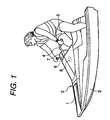
- Fig. 1 is an external view of a compact surface propelled vessel in accordance with an embodiment of the invention.
- Handlebars 4 are attached to a central upper portion of a vessel body 3 formed by joining a deck 1 and a hull 2.
- An antenna 6 for transmitting and receiving a collation signal radio wave with respect to the transponder 5 is provided in a steering-shaft accommodating section 7 formed of a soft material such as urethane and constituting an attaching portion for attaching the handlebars 4.
- An identifying unit 8 for collating the driver by transmitting and receiving a collation signal for the driver through the antenna 6 is provided in the vessel body 3.
- An engine stopping apparatus of the invention is formed by the transponder 5 fitted on the driver side and by the antenna 6 and the identifying unit 8 provided on the vessel body side, as will be detailed later.
- the antenna 6, in terms of its position can be disposed not only at a root portion of the handlebars but also at an appropriate position inside the vessel body allowing transmission and reception with respect to the transponder 5 worn on the body by the driver by taking the output of a transceiver into consideration.
- the radio wave reaches the transponder 5 in whatever a posture the driver assumes, such as one in which the driver raises his or her arm, in the state in which the driver is aboard the vessel.
- the output of the transceiver is set in as narrow a range as possible so that the falling into water of the driver can be immediately detected when the driver has fallen into water, as will be described later.
- Fig. 2 is a schematic diagram of the engine stopping apparatus in accordance with the embodiment of the invention.
- An engine 9 is mounted in the vessel body. This engine 9 is started by a starter motor 10.
- the starter motor 10 is connected via a starter relay 11 to a battery 12 mounted in the vessel, and is also connected to a starter button 13.
- the engine 9 is ignited and driven by operating an ignition coil 15 by an igniter 14.
- a manual stop switch 20 is connected to the igniter 14, so that the engine can be stopped manually, as required.
- the identifying unit 8 which is connected to the antenna 6 provided in the vessel body, is provided.
- This identifying unit 8 includes a transceiver 16 for transmitting and receiving a collation radio wave through the antenna 6; a collating circuit 17 for subjecting the transmitted or received collation radio wave to analyzing processing; and a control circuit 18 for driving the engine on the basis of the result of processing by the collating circuit 17.
- the collating circuit 17 (or the control circuit 18) has a storage circuit, in which identification information registered in advance is stored, transmits a collation signal to the transponder 5, confirms the presence or absence of its response signal, and collates it with the registered identification information.
- the control circuit 18 is connected to the battery 12, the starter button 13, and the igniter 14, and sets the engine 9 in a startable state or stops it depending on the result of collation by the collating circuit 17. If the engine 9 is set in a startable state, the engine 9 can be started if the starter button 13 is pressed.
- This control circuit 18 may be configured by using an engine control unit (ECU) originally provided for controlling the operation of the engine 9 and by adding a routine for collation determination to the ECU.
- ECU engine control unit
- an arrangement may be provided such that a main switch 19 for turning on the power during the starting of the engine is provided between the control circuit 18 and the battery 12. This main switch 19 may be omitted.
- the driver rides on the vessel.
- the driver presses the starter button 13. Consequently, the power source of the identifying unit 8 is turned on.
- a query radio wave (collation signal) is transmitted from the collating circuit 17 through the transceiver 16 and the antenna 6, and energy necessary for a responding operation is imparted to the transponder 5.
- the transponder 5 Upon obtaining electric power on the basis of the principle of electromagnetic induction, the transponder 5 returns as a response signal ID data (identification information) inputted in advance.
- ID data identification information
- the power source for the starter relay 11 and the igniter 14 is turned on by the control circuit 18. Incidentally, if a plurality of items of identification information are registered in advance, the use by a plurality of persons becomes possible.
- the starter motor 10 is driven, and the ignition coil is operated to start the engine 9.
- the power source for the starter relay 11 and the igniter 14 is not turned on, and remains in the off state, so that the engine 9 is not started.
- main switch 19 an arrangement may be provided such that when the main switch 19 is turned on, the power source for the identifying unit 8 is turned on so as to start the collating operation.
- the collating circuit 17 constantly transmits the query radio wave to the transponder 5 at fixed periods, and receives the response signal from the transponder 5.
- the collating circuit 17 detects the absence of the response signal from the transponder 5
- the control circuit 18 turns off the circuit of the igniter 14 to stop the engine 9. As a result, the vessel body stops near the driver who has fallen into the water.
- the transponder to which identification information has been inputted is held on the driver side, it is possible to prevent theft by preventing unauthorized driving by a third party by identifying the driver with a simple arrangement without using a connecting cord such as a lanyard cord.
Landscapes
- Engineering & Computer Science (AREA)
- Mechanical Engineering (AREA)
- Chemical & Material Sciences (AREA)
- Combustion & Propulsion (AREA)
- Ocean & Marine Engineering (AREA)
- Output Control And Ontrol Of Special Type Engine (AREA)
- Combined Controls Of Internal Combustion Engines (AREA)
- Control Of Vehicle Engines Or Engines For Specific Uses (AREA)
Applications Claiming Priority (2)
| Application Number | Priority Date | Filing Date | Title |
|---|---|---|---|
| JP20059199 | 1999-07-14 | ||
| JP20059199A JP4205261B2 (ja) | 1999-07-14 | 1999-07-14 | エンジン停止装置 |
Publications (2)
| Publication Number | Publication Date |
|---|---|
| EP1069012A2 true EP1069012A2 (de) | 2001-01-17 |
| EP1069012A3 EP1069012A3 (de) | 2003-07-02 |
Family
ID=16426907
Family Applications (1)
| Application Number | Title | Priority Date | Filing Date |
|---|---|---|---|
| EP20000115246 Withdrawn EP1069012A3 (de) | 1999-07-14 | 2000-07-13 | Vorrichtung zum Abschalten eines Motors |
Country Status (3)
| Country | Link |
|---|---|
| US (1) | US6404071B1 (de) |
| EP (1) | EP1069012A3 (de) |
| JP (1) | JP4205261B2 (de) |
Cited By (6)
| Publication number | Priority date | Publication date | Assignee | Title |
|---|---|---|---|---|
| GB2382441A (en) * | 2001-11-24 | 2003-05-28 | Roke Manor Research | Theft deterrent system |
| US7131876B2 (en) | 2004-03-22 | 2006-11-07 | Yamaha Marine Kabushiki Kaisha | Control device for small watercraft |
| US7186154B2 (en) | 2003-06-06 | 2007-03-06 | Yamaha Hatsudoki Kabushiki Kaisha | Security system for watercraft |
| US7528501B2 (en) | 2005-05-20 | 2009-05-05 | Yamaha Hatsudoki Kabushiki Kaisha | Vehicle controller for straddle type vehicle |
| US7554217B2 (en) | 2005-05-20 | 2009-06-30 | Yamaha Hatsudoki Kabushiki Kaisha | Vehicle controller for a straddle type vehicle |
| US8130088B2 (en) | 2005-05-20 | 2012-03-06 | Yamaha Hatsudoki Kabushiki Kaisha | Vehicle controler for straddle type vehicle |
Families Citing this family (16)
| Publication number | Priority date | Publication date | Assignee | Title |
|---|---|---|---|---|
| JP2006213450A (ja) * | 2005-02-03 | 2006-08-17 | Nippon Yusoki Co Ltd | リーチ型フォークリフト |
| US7518489B2 (en) * | 2006-01-19 | 2009-04-14 | Honda Motor Co., Ltd. | Method and system for remote immobilization of vehicles |
| US20070208491A1 (en) * | 2006-03-01 | 2007-09-06 | Miller Bruce D | Wireless security and monitoring system for mechanized equipment |
| US20070241862A1 (en) * | 2006-04-12 | 2007-10-18 | Dimig Steven J | Transponder authorization system and method |
| GB2444967A (en) | 2006-06-20 | 2008-06-25 | Vision Eng | Marine safety system |
| JP5081103B2 (ja) * | 2008-08-22 | 2012-11-21 | ヤマハ発動機株式会社 | 船舶用盗難抑止装置およびそれを備えた船舶 |
| JP5929010B2 (ja) * | 2011-05-23 | 2016-06-01 | 日産自動車株式会社 | 車両用遠隔制御装置 |
| TWI657947B (zh) * | 2017-06-08 | 2019-05-01 | Acer Incorporated | 車上裝置及其操作方法、對應之交通工具及交通工具防盜系統之操作方法 |
| US10566685B2 (en) * | 2017-09-15 | 2020-02-18 | Cnh Industrial America Llc | Integrated mounting for vehicle immobilizer system antenna |
| US11250653B2 (en) * | 2019-02-13 | 2022-02-15 | Brunswick Corporation | Configurable remote control system and method for a marine vessel |
| JP7668453B2 (ja) | 2020-06-10 | 2025-04-25 | 日本発條株式会社 | 船舶、船舶制御装置、船舶制御方法およびプログラム |
| JP7130015B2 (ja) | 2020-06-10 | 2022-09-02 | 日本発條株式会社 | 自動操船システム、船舶制御装置、船舶制御方法およびプログラム |
| JP7496718B2 (ja) | 2020-06-10 | 2024-06-07 | 日本発條株式会社 | 船舶制御システム、船舶制御方法、プログラムおよび乗り物制御システム |
| JP7090664B2 (ja) | 2020-06-10 | 2022-06-24 | 日本発條株式会社 | 自動操船システム、船舶制御装置、船舶制御方法およびプログラム |
| JP2023001533A (ja) | 2021-06-21 | 2023-01-06 | ヤマハ発動機株式会社 | 船舶の制御装置およびシステム、船舶 |
| JP7676282B2 (ja) | 2021-09-29 | 2025-05-14 | 日本発條株式会社 | 船舶、船舶制御装置、船舶制御方法およびプログラム |
Family Cites Families (16)
| Publication number | Priority date | Publication date | Assignee | Title |
|---|---|---|---|---|
| JPS61291297A (ja) * | 1985-06-19 | 1986-12-22 | Sanshin Ind Co Ltd | 船舶の遠隔操舵装置 |
| US4674454A (en) * | 1985-08-22 | 1987-06-23 | Donald Phairr | Remote control engine starter |
| GB2233487A (en) * | 1988-06-06 | 1991-01-09 | Shurlok Detector Company | Vehicle protection system |
| US4946411A (en) * | 1988-10-20 | 1990-08-07 | Novey Richard T | Hand held remote control for outboard powerheads |
| NO921830D0 (no) * | 1992-05-08 | 1992-05-08 | Defa Electronic As | Anordning ved alarmsystemer, spesielt bil-alarmsystemer |
| US5349329B1 (en) * | 1993-05-07 | 1996-09-10 | Ideaz International Inc | Vehicle security apparatus and method |
| US5394820A (en) * | 1993-11-29 | 1995-03-07 | Dach; Samuel | Motorized water vehicle |
| US5592169A (en) * | 1993-12-24 | 1997-01-07 | Mitsui Kinzoku Kogyo Kabushiki Kaisha | Transmitter for vehicle remote control system |
| US5459448A (en) * | 1994-06-27 | 1995-10-17 | Dortenzio; Christopher J. | Automotive continuous protection anti-theft system |
| US5486806A (en) * | 1994-11-09 | 1996-01-23 | Firari; Harold A. | Anti-hijacking and theft prevention device for motor vehicles |
| US5942988A (en) * | 1995-09-15 | 1999-08-24 | Bulldog Security Alarm Systems | Remote engine starter with engine cutoff |
| US6116201A (en) * | 1995-12-22 | 2000-09-12 | Labken, Inc. | In-solenoid chip for undertaking plural functions |
| IL126673A (en) * | 1996-04-24 | 2002-08-14 | Murray Steve | Radio controlled engine kill switch |
| US5794580A (en) * | 1997-02-26 | 1998-08-18 | Remote Products Inc. | Remote start/stop system for magneto ignition engines |
| US6091340A (en) * | 1997-11-25 | 2000-07-18 | Lee; Brian | Remote on/off disable parts and system |
| US6072248A (en) * | 1998-08-05 | 2000-06-06 | Muise; Christopher Russel | Method of and system for externally and remotely disabling stolen or unauthorized operated vehicles by pursuing police and the like |
-
1999
- 1999-07-14 JP JP20059199A patent/JP4205261B2/ja not_active Expired - Lifetime
-
2000
- 2000-07-13 EP EP20000115246 patent/EP1069012A3/de not_active Withdrawn
- 2000-07-13 US US09/615,702 patent/US6404071B1/en not_active Expired - Lifetime
Non-Patent Citations (1)
| Title |
|---|
| None |
Cited By (6)
| Publication number | Priority date | Publication date | Assignee | Title |
|---|---|---|---|---|
| GB2382441A (en) * | 2001-11-24 | 2003-05-28 | Roke Manor Research | Theft deterrent system |
| US7186154B2 (en) | 2003-06-06 | 2007-03-06 | Yamaha Hatsudoki Kabushiki Kaisha | Security system for watercraft |
| US7131876B2 (en) | 2004-03-22 | 2006-11-07 | Yamaha Marine Kabushiki Kaisha | Control device for small watercraft |
| US7528501B2 (en) | 2005-05-20 | 2009-05-05 | Yamaha Hatsudoki Kabushiki Kaisha | Vehicle controller for straddle type vehicle |
| US7554217B2 (en) | 2005-05-20 | 2009-06-30 | Yamaha Hatsudoki Kabushiki Kaisha | Vehicle controller for a straddle type vehicle |
| US8130088B2 (en) | 2005-05-20 | 2012-03-06 | Yamaha Hatsudoki Kabushiki Kaisha | Vehicle controler for straddle type vehicle |
Also Published As
| Publication number | Publication date |
|---|---|
| US6404071B1 (en) | 2002-06-11 |
| EP1069012A3 (de) | 2003-07-02 |
| JP2001027137A (ja) | 2001-01-30 |
| JP4205261B2 (ja) | 2009-01-07 |
Similar Documents
| Publication | Publication Date | Title |
|---|---|---|
| US6404071B1 (en) | Engine stopping apparatus | |
| EP1717117B1 (de) | Fahrzeugdiebstahlsicherung und -system | |
| US5838227A (en) | Radio controlled engine kill switch | |
| JP2001088789A (ja) | 小型推進艇の盗難防止装置 | |
| US5635900A (en) | Antitheft apparatus for automotive vehicle and method of registering ID No. therein | |
| US20020130769A1 (en) | Vehicle management system | |
| US11364874B2 (en) | Control system of marine vessel and portable device for marine vessel | |
| US7279807B2 (en) | Vehicle electronic key system | |
| JP4022913B2 (ja) | 無線装置 | |
| JP3875706B2 (ja) | エンジン始動システム | |
| US7081028B1 (en) | Portable control device used as a security and safety component of a marine propulsion system | |
| JP2970642B2 (ja) | 車載遠隔制御装置 | |
| US7710244B2 (en) | Remote engine starting system and method | |
| US7564146B2 (en) | Moving body starting system | |
| EP1067028A3 (de) | Diebstahlsichere Vorrichtung für Fahrzeuge | |
| JP2010143526A (ja) | エンジン始動装置 | |
| JP2004025938A (ja) | 電子キーシステム | |
| US20070164610A1 (en) | Propellant anti-theft system | |
| JP2000329041A (ja) | エンジン始動制御装置 | |
| JP2710970B2 (ja) | 車輌盗難防止装置 | |
| JP2597173B2 (ja) | 車輌盗難防止装置 | |
| JP2006274814A (ja) | エンジン遠隔操作システム | |
| US7014517B2 (en) | Engine control apparatus | |
| EP1418097A2 (de) | Diebstahlsicherung | |
| JP2589171B2 (ja) | 車輌盗難防止装置 |
Legal Events
| Date | Code | Title | Description |
|---|---|---|---|
| PUAI | Public reference made under article 153(3) epc to a published international application that has entered the european phase |
Free format text: ORIGINAL CODE: 0009012 |
|
| AK | Designated contracting states |
Kind code of ref document: A2 Designated state(s): AT BE CH CY DE DK ES FI FR GB GR IE IT LI LU MC NL PT SE |
|
| AX | Request for extension of the european patent |
Free format text: AL;LT;LV;MK;RO;SI |
|
| PUAL | Search report despatched |
Free format text: ORIGINAL CODE: 0009013 |
|
| AK | Designated contracting states |
Designated state(s): AT BE CH CY DE DK ES FI FR GB GR IE IT LI LU MC NL PT SE |
|
| AX | Request for extension of the european patent |
Extension state: AL LT LV MK RO SI |
|
| 17P | Request for examination filed |
Effective date: 20031230 |
|
| AKX | Designation fees paid |
Designated state(s): DE FR IT |
|
| 17Q | First examination report despatched |
Effective date: 20040809 |
|
| RAP1 | Party data changed (applicant data changed or rights of an application transferred) |
Owner name: KABUSHIKI KAISHA MORIC |
|
| RTI1 | Title (correction) |
Free format text: A COMPACT VEHICLE WITH AN ENGINE STOPPING APPARATUS |
|
| GRAP | Despatch of communication of intention to grant a patent |
Free format text: ORIGINAL CODE: EPIDOSNIGR1 |
|
| STAA | Information on the status of an ep patent application or granted ep patent |
Free format text: STATUS: THE APPLICATION IS DEEMED TO BE WITHDRAWN |
|
| 18D | Application deemed to be withdrawn |
Effective date: 20071205 |