EP1069009A1 - Accouplement par friction, limitant le couple dans un rétracteur de ceinture de sécurité en particulier - Google Patents
Accouplement par friction, limitant le couple dans un rétracteur de ceinture de sécurité en particulier Download PDFInfo
- Publication number
- EP1069009A1 EP1069009A1 EP00113188A EP00113188A EP1069009A1 EP 1069009 A1 EP1069009 A1 EP 1069009A1 EP 00113188 A EP00113188 A EP 00113188A EP 00113188 A EP00113188 A EP 00113188A EP 1069009 A1 EP1069009 A1 EP 1069009A1
- Authority
- EP
- European Patent Office
- Prior art keywords
- belt
- coupling
- formations
- friction
- friction clutch
- Prior art date
- Legal status (The legal status is an assumption and is not a legal conclusion. Google has not performed a legal analysis and makes no representation as to the accuracy of the status listed.)
- Granted
Links
- 230000008878 coupling Effects 0.000 title claims abstract description 56
- 238000010168 coupling process Methods 0.000 title claims abstract description 56
- 238000005859 coupling reaction Methods 0.000 title claims abstract description 56
- 230000015572 biosynthetic process Effects 0.000 claims description 27
- 238000005755 formation reaction Methods 0.000 claims description 27
- 230000007246 mechanism Effects 0.000 claims description 6
- 238000009740 moulding (composite fabrication) Methods 0.000 claims 1
- 239000002184 metal Substances 0.000 description 4
- 230000009471 action Effects 0.000 description 3
- 238000010276 construction Methods 0.000 description 2
- 230000003068 static effect Effects 0.000 description 2
- 230000000903 blocking effect Effects 0.000 description 1
- 230000008859 change Effects 0.000 description 1
- 238000006073 displacement reaction Methods 0.000 description 1
- 239000000463 material Substances 0.000 description 1
- 230000007704 transition Effects 0.000 description 1
Images

Classifications
-
- B—PERFORMING OPERATIONS; TRANSPORTING
- B60—VEHICLES IN GENERAL
- B60R—VEHICLES, VEHICLE FITTINGS, OR VEHICLE PARTS, NOT OTHERWISE PROVIDED FOR
- B60R22/00—Safety belts or body harnesses in vehicles
- B60R22/34—Belt retractors, e.g. reels
- B60R22/341—Belt retractors, e.g. reels comprising energy-absorbing means
- B60R22/3413—Belt retractors, e.g. reels comprising energy-absorbing means operating between belt reel and retractor frame
-
- F—MECHANICAL ENGINEERING; LIGHTING; HEATING; WEAPONS; BLASTING
- F16—ENGINEERING ELEMENTS AND UNITS; GENERAL MEASURES FOR PRODUCING AND MAINTAINING EFFECTIVE FUNCTIONING OF MACHINES OR INSTALLATIONS; THERMAL INSULATION IN GENERAL
- F16D—COUPLINGS FOR TRANSMITTING ROTATION; CLUTCHES; BRAKES
- F16D7/00—Slip couplings, e.g. slipping on overload, for absorbing shock
- F16D7/02—Slip couplings, e.g. slipping on overload, for absorbing shock of the friction type
- F16D7/021—Slip couplings, e.g. slipping on overload, for absorbing shock of the friction type with radially applied torque-limiting friction surfaces
-
- B—PERFORMING OPERATIONS; TRANSPORTING
- B60—VEHICLES IN GENERAL
- B60R—VEHICLES, VEHICLE FITTINGS, OR VEHICLE PARTS, NOT OTHERWISE PROVIDED FOR
- B60R22/00—Safety belts or body harnesses in vehicles
- B60R22/28—Safety belts or body harnesses in vehicles incorporating energy-absorbing devices
- B60R2022/285—Safety belts or body harnesses in vehicles incorporating energy-absorbing devices using friction surfaces
-
- B—PERFORMING OPERATIONS; TRANSPORTING
- B60—VEHICLES IN GENERAL
- B60R—VEHICLES, VEHICLE FITTINGS, OR VEHICLE PARTS, NOT OTHERWISE PROVIDED FOR
- B60R22/00—Safety belts or body harnesses in vehicles
- B60R22/34—Belt retractors, e.g. reels
- B60R22/46—Reels with means to tension the belt in an emergency by forced winding up
- B60R22/4676—Reels with means to tension the belt in an emergency by forced winding up comprising energy-absorbing means operating between belt reel and retractor frame
Definitions
- the invention relates to a friction clutch, in particular for Torque limitation in a belt retractor, with two each other opposite coupling surfaces and one between the coupling surfaces arranged friction element.
- the invention also relates to a Belt retractor with a belt reel rotatably mounted in a frame and a locking mechanism for the belt reel with at least one with the belt reel connected locking disc and one in the power flow path Torque limiting element arranged between the belt reel and the locking disk.
- Known friction clutches have a metal disk as the friction element on, which is arranged between two clutch plates and on both sides is provided with a clutch lining.
- the clutch lining provides On the one hand, a high frictional force to the clutch plates is safe and is on the other hand, designed to withstand the pressure and temperature loads has grown in the company.
- the friction element is therefore always made up of several Parts composed of different materials. To the required Contact pressure and thus to ensure sufficient friction, the clutch plates and the friction element with the help compressed by a separate spring.
- belt force limitation is thereby achieved achieved that in the power flow path between the belt spool and Locking disc is arranged a torsion bar, which is when exceeded a predetermined torque twisted and plastic deformed.
- a controlled torque limit is only here once and in one direction possible.
- the invention aims to provide a friction clutch and a belt retractor Torque limitation can be created in two directions work force-limiting and at the same time simply constructed and inexpensive are producible.
- a friction clutch in particular for Torque limitation in a belt retractor, with two opposite one another Coupling surfaces and one between the coupling surfaces arranged friction element is provided, in which the friction element as flat spring component is formed with formations, the Formations at least partially on one of the coupling surfaces issue.
- Such a friction clutch is particularly simple and inexpensive producible, since the required contact pressure between Friction element and clutch surfaces applied by the friction element itself is because this is designed as a spring component. A separate Pressure spring can thus be omitted.
- the friction element can, for example produced in a simple manner as a sheet metal stamping element at low cost become.
- the torque that can be transmitted through the friction clutch is substantially determined by the spring force of the spring component.
- the formations have in one Direction parallel to the coupling surfaces a circular section Cross section on. With a circular cross-section good spring properties are achieved. In tangential Direction to the circular section-shaped cross section of the formations the transferable friction force is also independent of direction.
- the spring component is advantageously in the form of a wavy band educated. Such a wavy band is simple and is suitable for arrangement between concentric coupling surfaces. Both the formations partially in contact with the first coupling surface as well as those partially in contact with the second coupling surface Formations of the spring component then have a circular section Cross-section. These measures also allow that the friction element consists of a single component.
- the spring component as a cylinder is designed with resilient shapes.
- Friction element made of a single component and is between two concentric Coupling surfaces particularly easy to assemble because of the Cylinder has a certain inherent stability and so easily between the coupling surfaces can be pressed.
- the spring component designed as a plate with resilient formations.
- the Spring component also consists of a single component and can in can be produced in a particularly simple manner as a stamped sheet metal part.
- a belt retractor with one in one Frame rotatably mounted belt reel, a locking mechanism for the Belt reel with at least one locking disk connected to the belt reel and one in the power flow path between the belt reel and the Locking disk arranged torque limiting element provided at which the torque limiting element as a friction clutch according to the invention is trained.
- a belt retractor acts in two directions force limiting, since the friction clutch torque in two directions limited. This means that peak belt force values can be achieved both when the belt reel is blocked when the vehicle or belt is sensitive, and when Insert one that engages the belt spool via the friction clutch Belt tensioners can be avoided.
- the belt retractor according to the invention can also be used after one Torque limit can be reused.
- the first coupling surface is on a the belt reel rotatably connected first clutch plate and the second coupling surface on a rotationally fixed with the locking disc connected second clutch plate provided, and between the Coupling plates is a plate with resilient shapes.
- the first coupling surface through an outer surface of an extension of a with the belt reel rotationally connected belt reel axis and the second Coupling surface through an inner surface of a rotatable with the Locking disk connected hollow cylinder is formed.
- Such a Belt retractor requires only one to realize the friction clutch low construction costs, since only the change of existing ones Components, namely the belt reel axis and the locking disc, and that Spring component are required.
- the belt spool axis only has to one, for example, extending outside the frame Extension must be provided, and on the lock washer must for Belt reel axis concentric hollow cylinder are attached.
- the Spring component is then on the extension of the belt reel axis and in inserted the hollow cylinder of the locking disc.
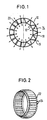
- FIG. 1 shows two concentrically mutually arranged coupling surfaces 10 and 12. On the right Side of Figure 1 is between these coupling surfaces 10 and 12 band-shaped spring component 14 arranged.
- the band-shaped spring component 14 has formations that are partially on the first coupling surface 10 adjacent first sections 16 and partially on the second coupling surface Form 12 adjacent second sections 18. Both the first sections 16 and also second sections 18 point in FIG a direction parallel to the coupling surfaces 10 and 12 a circular section Cross section on. Through the circular section Formations of the spring component 14 takes the form of a wavy band.
- the spring component 14 is between the coupling surfaces 10 and 12 pressed so that by the spring action of Spring component 14, the first sections 16 a force on the coupling surface 10 and the second sections 18 a force on the coupling surface Exercise 12. Those exerted on the coupling surfaces 10 and 12 Forces are symbolized by arrows in FIG. 1.
- the spring action of the spring component 14 between the coupling surfaces 10 and 12 is symbolized in the left part of FIG. 1 by coil springs 20, which are arranged between the coupling surfaces 10 and 12 and on they exert a force.
- Each shaft of the spring component 14 behaves like a spring 20, the force of which is proportional to the elastic range Spring constants and for deflecting the spring.
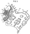
- a spring component 22 which as Cylinder with resilient formations 24 is formed.
- the formations 24 have an elongated shape and a plurality of formations 24 are adjacent to each other with their respective long sides Circumference of the cylinder 22 arranged around.
- the cylinder 22 has one certain intrinsic stability so that it is easily concentric between two Coupling surfaces can be pressed.
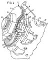
- FIG. 3 shows a first embodiment of an inventive Belt retractor 30.
- the belt retractor 30 has a frame 32, one in the frame 32 mounted belt reel 34 and a locking mechanism for the belt reel 34.
- the blocking mechanism consists of a Locking disk 36 with locking teeth 38.
- a pawl 40 by a conventional control mechanism that is sensitive to the vehicle and the seat belt, which is not shown, in the locking teeth 38th be controlled.
- the belt retractor 30 is used to limit the belt force provided with a friction clutch 42 which in the power flow between the Belt reel 34 and the locking disk 36 is arranged.
- the friction clutch 42 consists of the locking disk 36, a clutch plate 44 and one arranged between the locking disk 36 and the clutch plate 44 Spring plate 46.
- the spring plate 46 is designed as a stamped sheet metal part and has resilient formations 48 which are circular in two rows are arranged around the center of the circular plate 46.
- a Belt reel axis 50 is fixedly connected to the belt reel 34 and extends through the frame 32, the locking teeth 38, the locking disc 36, the spring plate 46 and the clutch plate 44 therethrough. While the locking disc 36 is rotatably mounted on the belt reel axis 50 is, the clutch plate 44 is rotationally fixed but longitudinally displaceable attached to the belt reel axis 50.
- the belt spool axis 50 a plurality of longitudinal grooves 52, in the lugs 54 of the clutch plate 44th intervention.
- the mother 56 is tightened more or less strongly.
- the formations 48 of the Spring plate 46 one in a direction parallel to the coupling surfaces have circular cross-section.
- the formations 48 thereby have a good spring action, and the friction clutch 42 can limit torque in two directions.
- the single ones Formations 48 of the spring plate 46 are formed by straight sections 58 connected with each other. During the formations 48 first sections of the spring plate 46, which on the by the frame 32 facing Surface of the clutch plate 44 formed first clutch surface the straight sections 58 form second sections, which rest on the second coupling surface, which is caused by the of the Frame 32 facing surface of the locking disk 36 is formed.
- the pawl 40 becomes vehicle or belt-sensitive controlled in the locking teeth 38 of the locking disk 36, so that the belt reel 34 is blocked relative to the frame 32 and no more webbing can be pulled off the belt reel 34.
- the friction clutch 42 must transmit a torque. Exceeds this torque to be transmitted from the friction clutch 42 predetermined value, will also be the maximum between those by the Formations 48 formed first sections and the first coupling surface or at most between those through the straight sections 58 formed second sections and the second coupling surface transferable Frictional force exceeded, so that the clutch disc 44 can rotate relative to the locking disk 36.
- FIG. 5 A second embodiment of a belt retractor according to the invention 60 is shown in FIG. 5.
- the belt retractor 60 shown in FIGS. 3 and 4 has the belt retractor 60 a frame 62, a belt reel 64, a locking disk 66 with locking teeth 68 and a pawl controllable into the locking toothing 68 70 on.
- the belt spool 64 has one fixed to the belt spool 64 connected axis, which extends beyond the frame 62 extending extension 72 has.
- the locking disk 66 is fixed with provided a hollow cylinder 74 in which the extension 72 of the Belt reel axis extends.
- One from a cylinder 76 with resilient Formations 78 existing spring component is between the extension 72 of the belt reel axis and the hollow cylinder 74 of the locking disk 66 pressed in.
- the provided in the belt retractor 60 friction clutch Torque is limited by a lateral surface of the extension 72, the cylinder 76 with resilient formations 78 and the Inner surface of the hollow cylinder 74 is formed.
- the arrangement of the friction clutch shown is the relative speed equal between the coupling surfaces over the entire coupling surfaces, so that the existing from the cylinder 76 with the formations 78 Spring component is loaded evenly everywhere.
Landscapes
- Engineering & Computer Science (AREA)
- General Engineering & Computer Science (AREA)
- Mechanical Engineering (AREA)
- Automotive Seat Belt Assembly (AREA)
- Mechanical Operated Clutches (AREA)
Applications Claiming Priority (2)
| Application Number | Priority Date | Filing Date | Title |
|---|---|---|---|
| DE29912154U DE29912154U1 (de) | 1999-07-12 | 1999-07-12 | Reibkupplung |
| DE29912154U | 1999-07-12 |
Publications (2)
| Publication Number | Publication Date |
|---|---|
| EP1069009A1 true EP1069009A1 (fr) | 2001-01-17 |
| EP1069009B1 EP1069009B1 (fr) | 2004-12-29 |
Family
ID=8076031
Family Applications (1)
| Application Number | Title | Priority Date | Filing Date |
|---|---|---|---|
| EP00113188A Expired - Lifetime EP1069009B1 (fr) | 1999-07-12 | 2000-07-03 | Rétracteur de ceinture de sécurité avec accouplement par friction |
Country Status (4)
| Country | Link |
|---|---|
| US (1) | US6454201B1 (fr) |
| EP (1) | EP1069009B1 (fr) |
| DE (2) | DE29912154U1 (fr) |
| ES (1) | ES2234481T3 (fr) |
Cited By (7)
| Publication number | Priority date | Publication date | Assignee | Title |
|---|---|---|---|---|
| EP1407922A3 (fr) * | 2002-10-11 | 2005-05-04 | Takata Corporation | Siège pour enfant |
| WO2012095133A1 (fr) * | 2011-01-12 | 2012-07-19 | Autoliv Development Ab | Enrouleur de ceinture comportant un appareil de limitation de la force régulé par la vitesse |
| US9327681B2 (en) | 2011-11-30 | 2016-05-03 | Autoliv Development Ab | Belt retractor with two force-limiting devices acting in parallel |
| US9884605B2 (en) | 2012-08-15 | 2018-02-06 | Autoliv Development Ab | Force-limiting device for a seat belt system |
| US9969353B2 (en) | 2013-10-16 | 2018-05-15 | Autoliv Development Ab | Force-limiting device for a seat belt system |
| US10053051B2 (en) | 2014-02-06 | 2018-08-21 | Autoliv Development Ab | Seat belt retractor with a velocity-controlled load limiting device |
| WO2019063469A1 (fr) * | 2017-09-27 | 2019-04-04 | Trw Automotive Gmbh | Rétracteur de ceinture |
Families Citing this family (13)
| Publication number | Priority date | Publication date | Assignee | Title |
|---|---|---|---|---|
| GB2358614B (en) | 2000-01-27 | 2003-05-14 | Breed Automotive Tech | Retractor |
| JP3977838B2 (ja) * | 2002-04-27 | 2007-09-19 | キー セーフティー システムズ、 インコーポレイテッド | 多荷重安定化構成付きシートベルトリトラクタ |
| DE20217632U1 (de) | 2002-11-14 | 2003-03-27 | TRW Occupant Restraint Systems GmbH & Co. KG, 73553 Alfdorf | Gurtaufroller |
| EP1435313B1 (fr) * | 2003-01-03 | 2007-05-09 | Key Safety Systems, Inc. | Rétracteur |
| DE10352327A1 (de) * | 2003-11-06 | 2005-06-09 | Fag Kugelfischer Ag | Verbund einer Bremsscheibe mit Nabe |
| DE102004008173A1 (de) * | 2004-02-19 | 2005-09-15 | Trw Automotive Gmbh | Reibungskupplung |
| GB2424045A (en) * | 2005-03-07 | 2006-09-13 | John Phillip Chevalier | Centrifugal clutch which is rotationally balanced when engaged |
| DE202005013681U1 (de) * | 2005-08-30 | 2005-12-22 | Trw Automotive Gmbh | Gurtaufroller-Drehmomentbegrenzer |
| DE102006027897A1 (de) * | 2006-06-17 | 2007-12-27 | Volkswagen Ag | Sicherheitsgurteinrichtung für ein Kraftfahrzeug |
| DE102007018086A1 (de) * | 2007-04-17 | 2008-10-23 | Hs Products Engineering Gmbh | Gurtaufroller für einen Fahrzeugsicherheitsgurt |
| GB2452768A (en) * | 2007-09-14 | 2009-03-18 | Husqvarna Ab | Chainsaw with tension adjusting knob and clutch arrangement |
| US8684624B2 (en) * | 2008-07-01 | 2014-04-01 | Saint-Gobain Performance Plastics Rencol Limited | Tolerance ring |
| DE102010026285B4 (de) | 2010-07-06 | 2014-02-06 | Autoliv Development Ab | Kraftbegrenzungseinrichtung für ein Kraftfahrzeug |
Citations (5)
| Publication number | Priority date | Publication date | Assignee | Title |
|---|---|---|---|---|
| DE916370C (de) * | 1951-08-08 | 1954-08-09 | Star Kugelhalter Ges M B H Deu | UEberlastungskupplung |
| US2779175A (en) * | 1955-01-03 | 1957-01-29 | Lear Inc | Friction disc for a slipping type clutch |
| GB2175358A (en) * | 1985-04-26 | 1986-11-26 | Andrew Kennedy | Slip-drive assembly |
| WO1997027088A1 (fr) * | 1996-01-24 | 1997-07-31 | Alliedsignal Limited | Bobine d'enrouleur |
| DE29816280U1 (de) * | 1998-09-10 | 1999-01-21 | TRW Occupant Restraint Systems GmbH & Co. KG, 73553 Alfdorf | Vorrichtung zur Kraftbegrenzung |
Family Cites Families (24)
| Publication number | Priority date | Publication date | Assignee | Title |
|---|---|---|---|---|
| DE187002C (fr) * | ||||
| DE434451C (de) | 1926-09-25 | Koenig & Bauer Schnellpressfab | Maschine zur Herstellung von Stereotypie-Matrizen mittels auf den Matrizenkarton einwirkender Buersten | |
| DE332137C (de) * | 1921-01-22 | Carl Birkenhauer | Kupplung | |
| US1165772A (en) * | 1914-12-08 | 1915-12-28 | Philadelphia Gear Works | Slip-gear. |
| DE473330C (de) | 1926-01-31 | 1929-03-15 | Geza Austerweil Dr | Verfahren zur Herstellung eines wasserloeslichen Pinenderivates |
| DE809877C (de) * | 1948-10-02 | 1951-08-02 | G Boley Fa | Rasteneinrichtung |
| US3363478A (en) * | 1964-08-19 | 1968-01-16 | Corning Glass Works | Driving means for rotary heat exchangers |
| CH473330A (de) * | 1965-12-30 | 1969-05-31 | Titt Georg | Vorrichtung zur Übertragung von Drehmomenten und Verfahren zur Herstellung dieser Vorrichtung |
| DE1935539C2 (de) * | 1969-07-12 | 1984-10-25 | Adam Opel AG, 6090 Rüsselsheim | Kraftbegrenzer für Sicherheitsgurte |
| DE6932536U (de) * | 1969-08-18 | 1969-11-27 | Metabowerke Kg | Rutschkupplung |
| DD97279A1 (fr) * | 1972-02-24 | 1973-04-23 | ||
| DE2230994C2 (de) * | 1972-06-24 | 1982-08-12 | Kangol-Teka Autoteile GmbH, 6238 Hofheim | Sicherheitsgurt-Sperrvorrichtung mit Bremseinrichtung |
| US3905562A (en) * | 1973-05-25 | 1975-09-16 | Kangol Magnet Ltd | Vehicle safety belt retractors |
| US4043437A (en) * | 1975-12-19 | 1977-08-23 | Lipe-Rollway Corporation | Torque limiting clutch brake |
| US4190138A (en) * | 1978-01-03 | 1980-02-26 | Bendall Wilfrid H | Automatic clutch |
| US4222246A (en) * | 1978-12-11 | 1980-09-16 | Roller Bearing Company Of America | Slip clutch |
| US4878880A (en) * | 1987-08-20 | 1989-11-07 | Itt Corporation | Clutch apparatus |
| FR2663135B1 (fr) * | 1990-06-11 | 1992-10-09 | Fillon Pichon Sa | Dispositif limiteur de couples pour centre modulaire de melangeage, notamment pour peintures et produits analogues. |
| JP3370397B2 (ja) | 1993-10-06 | 2003-01-27 | タカタ株式会社 | シートベルト巻取装置 |
| DE4344151A1 (de) * | 1993-12-23 | 1995-06-29 | Grohe Armaturen Friedrich | Überlastsicherung für ein Betätigungsglied |
| DE4445017A1 (de) * | 1994-03-12 | 1995-09-14 | Kupplungstechnik Gmbh | Überlastkupplung |
| US5607023A (en) * | 1994-12-13 | 1997-03-04 | Milwaukee Electric Tool Corp. | Impact absorption mechanism for power tools |
| US5707291A (en) * | 1996-02-16 | 1998-01-13 | Presstek, Inc. | Stressed hoop slip clutch |
| US5810668A (en) * | 1996-04-12 | 1998-09-22 | Simpson International (Uk) Ltd. | Torsional shock isolated fuel pump drive gear assembly |
-
1999
- 1999-07-12 DE DE29912154U patent/DE29912154U1/de not_active Expired - Lifetime
-
2000
- 2000-07-03 EP EP00113188A patent/EP1069009B1/fr not_active Expired - Lifetime
- 2000-07-03 DE DE50009077T patent/DE50009077D1/de not_active Expired - Lifetime
- 2000-07-03 ES ES00113188T patent/ES2234481T3/es not_active Expired - Lifetime
- 2000-07-11 US US09/614,098 patent/US6454201B1/en not_active Expired - Lifetime
Patent Citations (5)
| Publication number | Priority date | Publication date | Assignee | Title |
|---|---|---|---|---|
| DE916370C (de) * | 1951-08-08 | 1954-08-09 | Star Kugelhalter Ges M B H Deu | UEberlastungskupplung |
| US2779175A (en) * | 1955-01-03 | 1957-01-29 | Lear Inc | Friction disc for a slipping type clutch |
| GB2175358A (en) * | 1985-04-26 | 1986-11-26 | Andrew Kennedy | Slip-drive assembly |
| WO1997027088A1 (fr) * | 1996-01-24 | 1997-07-31 | Alliedsignal Limited | Bobine d'enrouleur |
| DE29816280U1 (de) * | 1998-09-10 | 1999-01-21 | TRW Occupant Restraint Systems GmbH & Co. KG, 73553 Alfdorf | Vorrichtung zur Kraftbegrenzung |
Cited By (9)
| Publication number | Priority date | Publication date | Assignee | Title |
|---|---|---|---|---|
| EP1407922A3 (fr) * | 2002-10-11 | 2005-05-04 | Takata Corporation | Siège pour enfant |
| US7029068B2 (en) | 2002-10-11 | 2006-04-18 | Takata Corporation | Child seat |
| WO2012095133A1 (fr) * | 2011-01-12 | 2012-07-19 | Autoliv Development Ab | Enrouleur de ceinture comportant un appareil de limitation de la force régulé par la vitesse |
| US9242617B2 (en) | 2011-01-12 | 2016-01-26 | Autoliv Development Ab | Seat belt retractor with a speed-regulated force-limiting device |
| US9327681B2 (en) | 2011-11-30 | 2016-05-03 | Autoliv Development Ab | Belt retractor with two force-limiting devices acting in parallel |
| US9884605B2 (en) | 2012-08-15 | 2018-02-06 | Autoliv Development Ab | Force-limiting device for a seat belt system |
| US9969353B2 (en) | 2013-10-16 | 2018-05-15 | Autoliv Development Ab | Force-limiting device for a seat belt system |
| US10053051B2 (en) | 2014-02-06 | 2018-08-21 | Autoliv Development Ab | Seat belt retractor with a velocity-controlled load limiting device |
| WO2019063469A1 (fr) * | 2017-09-27 | 2019-04-04 | Trw Automotive Gmbh | Rétracteur de ceinture |
Also Published As
| Publication number | Publication date |
|---|---|
| US6454201B1 (en) | 2002-09-24 |
| EP1069009B1 (fr) | 2004-12-29 |
| DE29912154U1 (de) | 1999-11-25 |
| DE50009077D1 (de) | 2005-02-03 |
| ES2234481T3 (es) | 2005-07-01 |
Similar Documents
| Publication | Publication Date | Title |
|---|---|---|
| EP1069009B1 (fr) | Rétracteur de ceinture de sécurité avec accouplement par friction | |
| DE19857199B4 (de) | Automatisch nachstellbare Reibungskupplung | |
| DE10046705C1 (de) | Bremsscheiben-/Nabenverbindung für Fahrzeugscheibenbremsen | |
| DE102008063639B4 (de) | Gurtaufroller mit schaltbarem Gurtkraftbegrenzer | |
| DE68911826T2 (de) | Drehmomentmessfühler. | |
| DE10122910B4 (de) | Rückhaltevorrichtung für einen Fahrzeuginsassen | |
| DE29605200U1 (de) | Gurtaufroller mit an der Gurtspule angreifendem Gurtstraffer | |
| DE4336445C2 (de) | Stelleinrichtung mit einer Sicherungseinrichtung | |
| EP3529129B1 (fr) | Colonne de direction à dispositif d'absorption d'énergie pour un véhicule à moteur | |
| DE10061086B4 (de) | Sitzgurteinzieheinrichtung | |
| EP1433687A2 (fr) | Colonne de direction | |
| DE19510833A1 (de) | Kupplungsscheibe mit in Reihe geschalteten Federelementen | |
| DE4420251A1 (de) | Reibungskupplung | |
| DE2901933C2 (fr) | ||
| EP0208979A1 (fr) | Sécurité contre la surcharge | |
| DE2256582B2 (de) | Scheibendämpfungsanordnung für Reibkupplungen | |
| DE102006009304B3 (de) | Lenksäulenanordnung für Fahrzeuge | |
| DE102008011790A1 (de) | Gurtaufroller für ein Sicherheitsgurtsystem | |
| DE4409253A1 (de) | Befestigung von Belagfedersegmenten an der Mitnehmerscheibe | |
| EP1890908A1 (fr) | Systeme de reglage manuel conçu pour un appui lombaire d'un siege de vehicule | |
| DE2736329C3 (de) | Überlastkupplung | |
| EP1285827A1 (fr) | Rétracteur pour ceinture de sécurité de véhicule | |
| DE19847081A1 (de) | Beidseitig wirkender manueller Antrieb zur Erzeugung einer Drehbewegung | |
| DE102021209478B4 (de) | Gurtaufroller für einen Sicherheitsgurt | |
| DE10337252B4 (de) | Gurtspule für einen Gurtaufroller |
Legal Events
| Date | Code | Title | Description |
|---|---|---|---|
| PUAI | Public reference made under article 153(3) epc to a published international application that has entered the european phase |
Free format text: ORIGINAL CODE: 0009012 |
|
| AK | Designated contracting states |
Kind code of ref document: A1 Designated state(s): DE ES FR GB IT |
|
| AX | Request for extension of the european patent |
Free format text: AL;LT;LV;MK;RO;SI |
|
| 17P | Request for examination filed |
Effective date: 20010615 |
|
| AKX | Designation fees paid |
Free format text: DE ES FR GB IT |
|
| 17Q | First examination report despatched |
Effective date: 20020911 |
|
| GRAP | Despatch of communication of intention to grant a patent |
Free format text: ORIGINAL CODE: EPIDOSNIGR1 |
|
| GRAS | Grant fee paid |
Free format text: ORIGINAL CODE: EPIDOSNIGR3 |
|
| GRAA | (expected) grant |
Free format text: ORIGINAL CODE: 0009210 |
|
| RAP1 | Party data changed (applicant data changed or rights of an application transferred) |
Owner name: TRW AUTOMOTIVE GMBH |
|
| RTI1 | Title (correction) |
Free format text: SEAT BELT RETRACTOR WITH FRICTION COUPLING |
|
| AK | Designated contracting states |
Kind code of ref document: B1 Designated state(s): DE ES FR GB IT |
|
| PG25 | Lapsed in a contracting state [announced via postgrant information from national office to epo] |
Ref country code: GB Free format text: LAPSE BECAUSE OF FAILURE TO SUBMIT A TRANSLATION OF THE DESCRIPTION OR TO PAY THE FEE WITHIN THE PRESCRIBED TIME-LIMIT Effective date: 20041229 |
|
| REG | Reference to a national code |
Ref country code: GB Ref legal event code: FG4D Free format text: NOT ENGLISH |
|
| REF | Corresponds to: |
Ref document number: 50009077 Country of ref document: DE Date of ref document: 20050203 Kind code of ref document: P |
|
| REG | Reference to a national code |
Ref country code: ES Ref legal event code: FG2A Ref document number: 2234481 Country of ref document: ES Kind code of ref document: T3 |
|
| GBV | Gb: ep patent (uk) treated as always having been void in accordance with gb section 77(7)/1977 [no translation filed] |
Effective date: 20041229 |
|
| PLBE | No opposition filed within time limit |
Free format text: ORIGINAL CODE: 0009261 |
|
| STAA | Information on the status of an ep patent application or granted ep patent |
Free format text: STATUS: NO OPPOSITION FILED WITHIN TIME LIMIT |
|
| 26N | No opposition filed |
Effective date: 20050930 |
|
| ET | Fr: translation filed | ||
| PGFP | Annual fee paid to national office [announced via postgrant information from national office to epo] |
Ref country code: FR Payment date: 20060705 Year of fee payment: 7 |
|
| PGFP | Annual fee paid to national office [announced via postgrant information from national office to epo] |
Ref country code: ES Payment date: 20060717 Year of fee payment: 7 |
|
| PGFP | Annual fee paid to national office [announced via postgrant information from national office to epo] |
Ref country code: IT Payment date: 20070713 Year of fee payment: 8 |
|
| REG | Reference to a national code |
Ref country code: FR Ref legal event code: ST Effective date: 20080331 |
|
| PG25 | Lapsed in a contracting state [announced via postgrant information from national office to epo] |
Ref country code: FR Free format text: LAPSE BECAUSE OF NON-PAYMENT OF DUE FEES Effective date: 20070731 |
|
| REG | Reference to a national code |
Ref country code: ES Ref legal event code: FD2A Effective date: 20070704 |
|
| PG25 | Lapsed in a contracting state [announced via postgrant information from national office to epo] |
Ref country code: ES Free format text: LAPSE BECAUSE OF NON-PAYMENT OF DUE FEES Effective date: 20070704 |
|
| PG25 | Lapsed in a contracting state [announced via postgrant information from national office to epo] |
Ref country code: IT Free format text: LAPSE BECAUSE OF NON-PAYMENT OF DUE FEES Effective date: 20080703 |
|
| PGFP | Annual fee paid to national office [announced via postgrant information from national office to epo] |
Ref country code: DE Payment date: 20190731 Year of fee payment: 20 |
|
| REG | Reference to a national code |
Ref country code: DE Ref legal event code: R071 Ref document number: 50009077 Country of ref document: DE |
|
| REG | Reference to a national code |
Ref country code: DE Ref legal event code: R081 Ref document number: 50009077 Country of ref document: DE Owner name: ZF AUTOMOTIVE GERMANY GMBH, DE Free format text: FORMER OWNER: TRW AUTOMOTIVE GMBH, 73553 ALFDORF, DE Ref country code: DE Ref legal event code: R082 Ref document number: 50009077 Country of ref document: DE Representative=s name: PRINZ & PARTNER MBB PATENTANWAELTE RECHTSANWAE, DE |