EP1067828B1 - Sorfortiges Balancesteuerungsablauf für einen Ionisator - Google Patents
Sorfortiges Balancesteuerungsablauf für einen Ionisator Download PDFInfo
- Publication number
- EP1067828B1 EP1067828B1 EP00110030A EP00110030A EP1067828B1 EP 1067828 B1 EP1067828 B1 EP 1067828B1 EP 00110030 A EP00110030 A EP 00110030A EP 00110030 A EP00110030 A EP 00110030A EP 1067828 B1 EP1067828 B1 EP 1067828B1
- Authority
- EP
- European Patent Office
- Prior art keywords
- positive
- negative
- voltage value
- voltage power
- high voltage
- Prior art date
- Legal status (The legal status is an assumption and is not a legal conclusion. Google has not performed a legal analysis and makes no representation as to the accuracy of the status listed.)
- Expired - Lifetime
Links
Images


Classifications
-
- H—ELECTRICITY
- H05—ELECTRIC TECHNIQUES NOT OTHERWISE PROVIDED FOR
- H05F—STATIC ELECTRICITY; NATURALLY-OCCURRING ELECTRICITY
- H05F3/00—Carrying-off electrostatic charges
- H05F3/04—Carrying-off electrostatic charges by means of spark gaps or other discharge devices
-
- H10P95/00—
Definitions
- Air ionization is the most effective method of eliminating static charges on non-conductive materials and isolated conductors. Air ionizers generate large quantities of positive and negative ions in the surrounding atmosphere which serve as mobile carriers of charge in the air. As ions flow through the air, they are attracted to oppositely charged particles and surfaces. Neutralization of electrostatically charged surfaces can be rapidly achieved through the process.
- Air ionization may be performed using electrical ionizers which generate ions in a process known as corona discharge. Electrical ionizers generate air ions through this process by intensifying an electric field around a sharp point until it overcomes the dielectric strength of the surrounding air. Negative corona occurs when electrons are flowing from the electrode into the surrounding air. Positive corona occurs as a result of the flow of electrons from the air molecules into the electrode.
- the ionizer To achieve the maximum possible reduction in static charges from an ionizer of a given output, the ionizer must produce equal amounts of positive and negative ions. That is, the output of the ionizer must be "balanced.” If the ionizer is out of balance, the isolated conductor and insulators can become charged such that the ionizer creates more problems than it solves. Ionizers may become imbalanced due to power supply drift, power supply failure of one polarity, contamination of electrodes, degradation of electrodes, or ambient air conditions such as changes in permeability or humidity. In addition, the output of an ionizer may be balanced, but may drop below its desired level due to system component degradation.
- ionization systems incorporate monitoring, automatic balancing via feedback systems, and alarms for detecting uncorrected imbalances and out-of-range outputs.
- Most feedback systems are entirely or primarily hardware-based. Many of these feedback systems cannot provide very fine balance control, since feedback control signals are fixed based upon hardware component values. Furthermore, the overall range of balance control of such hardware-based feedback systems may be limited based upon the hardware component values. Also, many of the hardware-based feedback systems cannot be easily modified since the individual components are dependent upon each other for proper operation.
- a charged plate monitor is typically used to calibrate and periodically measure the actual balance of an electrical ionizer.
- the charged plate monitor is also used to measure static charge decay time. If the decay time is too slow or too fast, the ion output may be adjusted by increasing or decreasing the preset ion current value. This, adjustment is typically performed by adjusting two trim potentiometers (one for positive ion generation and one for negative ion generation).
- Ionization systems may be used to control static charge in an entire room or in a predefined work surface area.
- Fig. 1 shows a conventional "overhead ionized air blower" or “overhead ionizer” 10 for controlling static charge on top of work surface 12 .
- the overhead ionizer 10 provides a cushion of ionized air protection above the work surface 12 , such as from 0-4 inches above the work surface 12 .
- the overhead ionizer 10 is typically hung over the work surface, such as about 30 inches above the work surface.
- the overhead ionizer 10 includes therein a plurality of ionizers 14 and a plurality of fans 16 , each fan being associated with one ionizer 14 .
- One conventional scheme uses three pairs of ionizers 14 1 -14 3 /fans 16 1 -16 3 .
- the fans 16 create a unidirectional airflow downward from the ionizer 10 to the work surface 12 .
- Power is provided to the fans 16 in parallel with the respective ionizers 14 so that both are either on or off. Fan speed can be adjusted, but the adjustment simultaneously adjusts all fans equally.
- Conventional ionizers 14 contain analog trim potentiometers or digital potentiometers for making such adjustments. To make adjustments in a conventional overhead ionizer 10 , a person must reach up to the overhead ionizer 10 to adjust the analog potentiometers or to press UP/DOWN buttons which control digital potentiometer settings. Each ionizer 14 1 -14 3 has a separate set of potentiometers.
- One significant problem with the conventional balance adjustment scheme is that the person's physical movements for performing the adjustment and the physical presence of the person in or near the cushion of ionized air protection interferes with proper adjustment and may introduce sudden, large static charges into the work area.
- the ionizer merely corrects for the excess positive ions by moving towards a balanced condition wherein there are a lesser amount of excess positive ions. No effort is made to compensate for the few milliseconds of being too positive, such as by being too negative by the same amount for a few milliseconds.
- the present invention provides a scheme for balancing positive and negative ion output in an electrical ionizer having positive and negative ion emitters, and positive and negative high voltage power supplies associated with the respective positive and negative ion emitters.
- the scheme at least one of the positive and negative high voltage power supplies switches between a high state and a low state.
- An ion balance sensor is located close to the ion emitters and outputs a voltage value.
- An ion balance sensor set point voltage value is stored. The voltage value is set to provide a balanced ion condition in the work space near the electrical ionizer.
- the output voltage value of the ion balance sensor is compared with the set point voltage value.
- One of the switchable high voltage power supplies is switched to a high state when it is detected as a result of the comparison that the output voltage value of the ion balance sensor exceeds the set point voltage value in a first direction by a first predetermined amount, and the one of the switchable high voltage power supplies is switched to a low state when it is detected as a result of the comparison that the output voltage value of the ion balance sensor exceeds the set point voltage value in a second direction by a second predetermined amount, the second direction being opposite of the first direction.
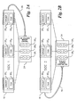
- Figs. 2A and 2B show a DC "overhead ionized air blower" or DC "overhead ionizer” 18 for controlling static charge in accordance with the present invention.
- the overhead ionizer 18 is preferably arranged in the same manner with respect to a work surface as the conventional overhead ionizer 10 of Fig. 1 .
- the overhead ionizer 18 includes therein a plurality of electrical ionizers 20 and a plurality of fans 22 , each fan being associated with one ionizer 20 .
- one preferred embodiment of the invention has three pairs of ionizers 20 1 -20 3 /fans 22 1 -22 3 .
- balance settings for the ionizers 20 are stored in memory associated with a microprocessor located inside the housing of the overhead ionizer 18 (shown schematically in Fig. 4 ). Additional details of the overhead ionizer 18 circuitry are discussed below.
- the remote control 24 is wired to the overhead ionizer 18 via detachable cable 26 , which may be a standard modular telephone cable. A length of seven feet is sufficient to allow the user to avoid the "keep out" zone (i.e., the zone where the user's presence and movements interfere with the balance adjustment).
- the remote control 24 includes a pair of (+)/(-) buttons 28 1 -28 3 to control balance for each of the ionizers 20 1 -20 3 .
- the pairs of buttons 28 1 -28 3 (generically, 28 1 -28 n ) are arranged sequentially with respect to each pair.
- the (+) and (-) buttons within each button pair may be arranged in any particular orientation.
- the remote control 24 is designed to have a particular working relationship between the buttons 28 , the ionizers 20 and the cable 26 .
- the button pair 28 nearest the end of the cable 26 which connects to the remote control 24 adjusts the ionizer 20 nearest the end of the cable 26 which connects to the overhead ionizer 18 .
- the button pair 28 farthest from the end of the cable 26 which connects to the remote control 24 adjusts the ionizer 20 farthest from the end of the cable 26 which connects to the overhead ionizer 18 .
- Intermediate button pairs 28 control respective intermediate ionizers 20 in the same order. This design makes use of the remote control 24 intuitive for the person adjusting the balance.
- the button pairs 28 become oriented in the same order as the ionizers 20 which they control, as shown by the dashed lines in Figs. 2A and 2B . Furthermore, the orientation remains the same regardless of whether the remote control 24 is located facing the front side (side 1) of the overhead ionizer 18 ( Fig. 2A ), or the rear side (side 2) of the overhead ionizer 18 ( Fig. 2B ). In addition, adjustments are easy to make even if the cable 26 is twisted or has a tortured path, or if the remote control 24 is held in other orientations with respect to the overhead ionizer 18 , such as rotated 90 degrees.
- the person performing the adjustment need only mentally note the relationship between the button pairs 28 , the ionizers 20 and the cable 26 by following the cable path and visually noting which button pairs 28 and ionizers 18 are closest and farthest from their respective ends of the cable 26 .
- this scheme it is not necessary to label the individual ionizers 20 or the button pairs 28 .
- the cable 26 may be replaced by a wireless system, such as by using a wireless remote control 24 containing an infrared transmitter and providing an infrared receiver on the overhead ionizer 18 .
- Fig. 3 shows a work area which contains a plurality of overhead ionizers 18 1 -18 n connected in a daisy-chain manner by RS-485 communication lines 32 to a monitoring computer 34 .
- a charged plate monitor 36 is placed on the work surface of overhead ionizer 18 1 to obtain an actual balance reading. If adjustments are necessary, the person making the adjustment plugs in the remote control 24 and adjusts the particular ionizer 20 1 , 20 2 or 20 3 that is most strongly influencing the charged plate monitor 36 .
- the remote control 24 may be plugged into an unused jack of the communication line connector, as shown in Fig. 3 .
- the communication line 32 may be removed, and the remote control 24 may be plugged therein (not shown).
- the charged plate monitor 36 may be moved along the work surface to check and adjust the balance of each ionizer 20 1 , 20 2 and 20 3 .
- the charged plate monitor 36 is moved to the work surface of overhead ionizer 18 2 , the remote control 24 is connected to the communication jack of the overhead ionizer 18 2 , and the balance adjustment process is repeated again.
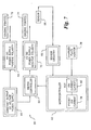
- Fig. 4 is a schematic block diagram of microprocessor-controlled circuitry for operating an overhead ionizer 18 .
- Fig. 4 shows overhead ionizer 18 1 and ionizer 20 1 associated therewith.
- the hardware components of the ionizer 20 1 include a low voltage DC fan 22 1 controlled by a DC motor 38 which draws air in through ionizing chamber 40 1 .
- the ionizing chamber 40 1 which is on the intake side of the fan 22 1 , contains ion emitters (points) 42 which are removable for maintenance.
- the exhaust side of the fan 22 1 contains an ion balance sensor 44 .
- the exhaust side of the fan 22 1 distributes the ionized air containing the positive and negative ions for static neutralization.
- the overhead ionizer 18 is powered internally by a universal input power supply capable of operating on any input power between 100-240 VDC, 50/60 Hz. Power input is by a standard IEC320 connector, with power output available at the opposite end by a standard IEC320 outlet.
- Each ionizing chamber 40 within each overhead ionizer 18 is energized by separate positive and negative high voltage power supplies 46 under the independent control of a processor 48 , which is preferably a microprocessor.
- the processor 48 includes a balance reference memory 50 and a comparator 52 .
- the memory 50 stores the balance reference values for each of the ionizers 20 associated with the overhead ionizer 18 .
- the memory 50 stores three voltage values, B REF1 , B REF2 and B REF3 .
- the balance reference value is the desired voltage value of the ion balance sensor 44 associated with the respective ionizer 20 .
- the measured balance, B MEAS1 as determined by the ion balance sensor 44 , and B REF1 are compared in the comparator 52 . If the values are equal, no adjustment is made to the positive or negative high voltage power supplies 46 . If the values are not equal, appropriate adjustments are made to the power supplies 46 until the values become equal. This process occurs continuously and automatically during operation of the ionizer 20 1 .
- balance readings are taken from a charged plate monitor to obtain an actual balance reading, B ACTUAL1 , in the work space near the ionizer 20 1 .
- B REF1 is adjusted up or down by using the remote control 24 .
- the charged plate monitor is moved to obtain actual balance reading, B ACTUAL2 and B ACTUAL3 , in the work spaces near the ionizer 20 2 and 20 3 , and the process described above is repeated for such ionizers. Due to manufacturing tolerances and system degradation over time, each ionizer 20 will thus likely have a different B REF value.
- Each overhead ionizer 18 includes an alarm 54 for signaling when the ion balance cannot be properly controlled, and when the ion current is out of range.
- the processor 48 outputs the alarm signal.
- the alarm signals are also transmitted via the communication line 32 to the monitoring computer 34 , if such a computer is attached.
- Fig. 5 is a self-explanatory flowchart of the software associated with the processor 48 .
- Microprocessor control of the ionizers 20 and fans 22 within each overhead ionizer 18 allows sophisticated features to be implemented, such as the following features:
- balance readings from an ion balance sensor are monitored and reviewed. If balance readings for recently measured cycles indicate that the balance is too negative, then the ON cycle of the negative power supply is decreased by a predetermined amount. Likewise, if balance readings for recently measured cycles indicate that the balance is too positive, then the ON cycle of the negative power supply is increased by a predetermined amount. The next set of balance readings are reviewed and further adjustments to the ON cycle of the negative power supply are made, if necessary.
- Fig. 6 illustrates the prior art scheme described above.
- the waveform in Fig. 6 is the pulse signal associated with the negative power supply wherein a 20 millisecond (ms) pulse width is used.
- the ON/OFF times are equally divided between the ON and OFF states (10 ms ON, 10 ms OFF).
- the balance control system detects an imbalanced condition, specifically, an excess of negative ions.
- the ON cycle of the negative power supply is decreased by a predetermined amount (e.g., 1 ms) during the next 20 ms cycle, thereby providing 9 ms ON and 11 ms OFF.
- the balance control system is still detecting an excess of negative ions so the ON cycle is further decreased, for example, by another 1 ms, thereby providing 8 ms ON and 12 ms OFF.
- balance has been achieved and the next cycle remains at 8 ms ON and 12 ms OFF.
- the process described above fails to provide quick short-term balance control since a plurality of cycles occur before the ionizer is brought back into balance. Typically, balance measurements from a plurality of past cycles (three cycles in the example of Fig. 6 ) are taken even before any corrective efforts are made. Furthermore, the corrective efforts require additional cycles before balance is achieved.
- the process described above also fails to provide long-term balance control. Referring to the example in Fig. 6 , the balance is too negative between time t 0 and t 7 . However, no effort is made to compensate for the extra negative ions generated during this time period, such as by subsequently producing extra positive ions in addition to rebalancing the ion output. Instead, balance control system works solely to reduce the excess negative ions. Thus, if the system remained in balance for the rest of the operation, or if the ionizer continually repeated the problem of producing excess negative ions, there would be a long-term imbalance of negative ions.
- Another important feature of the present invention is an improved balance control scheme which addresses the deficiencies described above by providing instantaneous short-term balance control and zero long-term balance control.
- One preferred embodiment of the improved balance control scheme works in conjunction with the overhead ionizer 18 described above with respect to Figs. 2-5 .
- the scheme may be applied to any type of ionizer.
- the scope of the invention is not limited to the overhead ionizer application described herein.
- Fig. 7 is a schematic block diagram of a balance control system 56 in accordance with the present invention.
- Fig. 8 is a balance sensor waveform generated using the system of Fig. 7 in a first embodiment of a balance control scheme.
- the system 56 includes a sensor 58 , sensor circuitry 60 , a microcontroller 62 , a switch controller 64 , a constant output DC voltage power supply 66 , a positive and negative polarity HV DC power supply 68 and 70 , and respective ionizing point(s) or pin(s) 72 and 74 .
- An optional air moving device (not shown) may be placed near the ionizing points 72 and 74 .
- the sensor 58 is placed near the ionizing points 72 and 74 to provide feedback to the microcontroller 62 .
- the output of the sensor 58 is connected to the input of the sensor circuitry 60 , and the output of the sensor circuitry 60 connects to an input of the microcontroller 62 .
- An output of the microcontroller 62 connects to a first input of the switch controller 64 and the output of the DC voltage power supply 66 connects to a second input of the switch controller 64 .
- the output of the DC voltage power supply 66 also connects to the input of the positive polarity HV DC power supply 68 .
- the output of the switch controller 64 connects to the input of the negative polarity HV DC power supply 70 .
- the positive polarity of the HV DC power supply 68 is continuously driven at a selected input voltage (e.g., +5V), and thus has a steady state DC output.
- the negative polarity of the HV DC power supply 70 is driven by the DC voltage power supply 66 through the switch controller 64 under the control of the microcontroller 62 . Due to this configuration, the negative polarity HV DC power supply 70 can produce a greater quantity of ions that the positive polarity HV DC power supply 68 .
- the negative polarity of the HV DC power supply 70 thus switches between a high state and a low state based upon the output control signals from the microcontroller 62 which controls the switch controller 64 .
- the positive polarity of the HV DC power supply 68 is switched and the negative polarity of the HV DC power supply 70 has a steady state DC output.
- both polarities of the HV DC power supply are switched.
- the high state is a fully switched on state wherein power is fully switched on
- the low state is a fully switched off state wherein power is fully switched off.
- the high state may be a first voltage level and the second state may be a second voltage level which is lower than the first voltage level, but not necessarily zero.
- Figs. 7 and 8 the operation of the microcontroller 62 and switch controller 64 is described with respect to a sensor voltage waveform received by the microcontroller 62 .
- the continuously driven positive polarity of the HV DC power supply 68 is turned fully on.
- the microcontroller 62 waits for the sensor 58 to exceed a predetermined but adjustable set point which is of the same polarity as the continuously driven positive power supply 68 .
- the set point may be a voltage level, such as +2V, correlated to an electrostatic analyzer (e.g., a charged plate monitor) placed at a specific distance from the ionizing device.
- the microcontroller 62 sets the sensor set point to the equal but opposite polarity voltage level, such as -2V, and the negative polarity HV DC supply 70 is turned on.
- the microcontroller 62 waits for the sensor 58 to exceed the new level (which is -2V in this example), at which time the previous sensor set point (which is +2V in this example) is loaded, and the negative polarity HV DC supply is turned off, beginning a new cycle.
- a "set point" of zero is the point in which a charged plate monitor should give a balance reading of zero.
- the balance control system described above may be used with the overhead ionizer 18 shown in Fig. 2A and 4 . Alternatively, the balance control system may be used in other types of ionizers. If the balance control system is used in the overhead ionizer 18 , the initial set point is stored. (The positive set point is equal to BREF + an offset number, whereas the negative set point is equal to BREF - the same offset number. If, during use, the positive supply has to be adjusted from the original set value (e.g., +2V to +2.2V), then the new set point is stored for subsequent turn-on.
- the original set value e.g., +2V to +2.2V
- the microcontroller 62 has a memory 78 for storing a preset ion current value, as well as an auxiliary memory 80 for storing an ion current value which is the latest ion current value. During operation, if a value exists in the auxiliary memory 80 , then that value is used. If no value exists in the auxiliary memory 80 , then the value in memory 78 is used.
- the scheme described above is essentially a pulse width modulation form of operation. Since the sensor level controls the supplies, differences of operation from cycle to cycle are accounted for, resulting in varying frequency and duty cycle. The net result is a more stable balance control in the short-term as well as in the long-term. That is, short-term imbalance conditions are corrected in every cycle, without having to wait a plurality of cycles as required by conventional balance control schemes. In fact, the average balance is always zero in every cycle. Accordingly, the long-term average balance is also always zero. As discussed above, conventional schemes inherently do not compensate for long-term imbalanced conditions.
- Fig. 8 operates on two reference levels (set points) and reacts according to present conditions. If something interferes with or inhibits the ionization process, no change of state occurs with respect to the negative polarity HV DC supply 70 until the proper set point is reached. This effectively lengthens the duty cycle. In contrast, if something enhances the ionization process, such as point cleaning, the set point limits are reached more quickly, resulting in a reduced duty cycle.
- the overall "frequency" is based upon the sensor set points, with higher set points resulting in a slower frequency. That is, the longer it takes to reach the set point, the less cycles will occur in a given period of time.
- the balance control system of the present invention allows the user to monitor the condition of the constantly driven HV DC supply (positive supply in the embodiment of Fig. 8 ) and to adjust for ionizing point wear. For example, a reduction in the output voltage of the positive supply may be detected by a reduction in the duty cycle of the negative supply.
- Fig. 9 is a balance sensor waveform generated using the system of Fig. 7 in a second embodiment of a balance control scheme.
- the negative supply is turned on when the output voltage of the ion balance sensor 58 exceeds the set point in a first direction (e.g., positive direction) by a first predetermined amount, and the negative supply is turned off when the output voltage of the ion balance sensor 58 exceeds the set point in a second direction (e.g., negative direction) by a second predetermined amount
- the first and second predetermined amounts may be the same, as shown in Fig. 9 , or they may be different amounts.
- the single set point voltage is the voltage which causes a zero voltage on a charged plate monitor (CPM) at a particular distance from the ionizer, such as 18 inches.
- CPM charged plate monitor
- the set point voltage is zero.
- the resultant sensor voltage waveform has a sinusoidal appearance.
- the lag time between the switching of the negative HV DC supply and the effect in the field on the actual ion balance, as measured by the sensor voltage contributes to the sinusoidal waveform.
- the scheme in Fig. 9 provides faster corrections for imbalance than the scheme in Fig. 8 , assuming that the processing speed of the sensor voltage checking process and the response time of the negative polarity high voltage power supply are the same in both schemes.
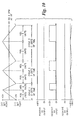
- Fig. 10 is a combined diagram of waveforms associated with the sensor and power supplies of Fig. 7 in a further illustration of the balance control system. Some of the waveforms in Fig. 10 are exaggerated or simplified to illustrate the invention. Fig. 10 illustrates a two sensor set point scheme, similar to Fig. 8 .
- the first waveform in Fig. 10 is a balance sensor waveform and shows how duty cycle and frequency may vary to maintain a balanced condition.
- the second waveform shows the constant output of the constantly on positive polarity HV DC supply 68 .
- the third waveform shows the input voltage of the negative polarity HV DC supply 70 (i.e. the drive voltage of the negative polarity HV DC supply 70 ).
- the fourth waveform shows the output of the negative polarity HV DC supply 70 . Due to the stored energy in the power supply 70 , the output voltage does not turn completely on and off even though the input drive voltage turns completely on and off. Instead, the output voltage rises and falls from a maximum output voltage as the drive voltage switches on and off. In the example of Fig.
- the output voltage varies between -5.6 kV and -6.0 kV as the drive voltage varies between 0V and 12V.
- Other switching schemes are within the scope of the invention.
- the switched power supply may have its input voltage switched between any two input voltage levels, not necessarily a fully switched off and fully switched on level.
Landscapes
- Elimination Of Static Electricity (AREA)
- Electrophonic Musical Instruments (AREA)
- Networks Using Active Elements (AREA)
- Tone Control, Compression And Expansion, Limiting Amplitude (AREA)
- Measuring Volume Flow (AREA)
Claims (10)
- Verfahren zum Ausgleichen der positiven und negativen Ionenausgabe in einem elektrischen Ionisator mit (i) einem positiven und einem negativen Ionenemitter und (ii) einer positiven und einer negativen Hochspannungs-Stromversorgung, die mit dem jeweiligen positiven bzw. negativen Ionenemitter assoziiert sind, wobei mindestens eine der positiven und der negativen Hochspannungs-Stromversorgung zwischen einem Hoch-Zustand und einem Niedrig-Zustand umschaltet, wobei das Verfahren die folgenden Schritte umfaßt:(a) Bereitstellen eines in der Nähe der Ionenemitter angeordneten Ionenausgleichssensors, wobei der Ionenausgleichssensor einen Spannungswert ausgibt;(b) Speichern eines Sollspannungswerts des Ionenausgleichssensors, wobei der Spannungswert so eingestellt wird, daß ein ausgeglichener Ionenzustand in dem Arbeitsraum in der Nähe des elektrischen Ionisators entsteht;(c) während des Betriebs des elektrischen Ionisators, Vergleichen des Ausgangsspannungswerts des Ionenausgleichssensors mit dem Sollspannungswert;(d) Umschalten einer der umschaltbaren Hochspannungs-Stromversorgungen in einen Hoch-Zustand, wenn als Ergebnis des Vergleichs detektiert wird, daß der Ausgangsspannungswert des Ionenausgleichssensors den Sollspannungswert in einer ersten Richtung um einen ersten vorbestimmten Betrag überschreitet; und(e) Umschalten der einen umschaltbaren Hochspannungs-Stromversorgurigen in einen Niedrig-Zustand, wenn als Ergebnis des Vergleichs detektiert wird, daß der Ausgangsspannungswert des Ionenausgleichssensors den Sollspannungswert in einer zweiten Richtung um einen zweiten vorbestimmten Betrag überschreitet, wobei die zweite Richtung der ersten Richtung entgegengesetzt ist.
- Verfahren nach Anspruch 1, wobei eine der positiven und der negativen Hochspannungs-Stromversorgung eine stationäre Gleichstromausgabe liefert und die andere der positiven und der negativen Hochspannungs-Stromversorgung zwischen einem Hoch-Zustand und einem Niedrig-Zustand umschaltet,
wobei Schritt (d) umfaßt, die umschaltbare Hochspannungs-Stromversorgung in einen Hoch-Zustand umzuschalten, wenn als Ergebnis des Vergleichs detektiert wird, daß der Ausgangsspannungswert des Ionenausgleichssensors den Sollspannungswert in einer ersten Richtung um einen ersten vorbestimmten Betrag überschreitet; und
wobei Schritt (e) umfaßt, die umschaltbare Hochspannungs-Stromversorgung in einen Niedrig-Zustand umzuschalten, wenn als Ergebnis des Vergleichs detektiert wird, daß der Ausgangsspannungswert des Ionenausgleichssensors den Sollspannungswert in einer zweiten Richtung um einen zweiten vorbestimmten Betrag überschreitet. - Verfahren nach Anspruch 1 oder 2, wobei die positive Hochspannungs-Stromversorgung eine stationäre Gleichstromausgabe liefert und die negative Hochspannungs-Stromversorgung zwischen einem Hoch-Zustand und einem Niedrig-Zustand umschaltet, und die Schritte (d) und (e) die negative Hochspannungs-Stromversorgung in den Hoch- und den Niedrig-Zustand umschalten.
- Verfahren nach mindestens einem der vorhergehenden Ansprüche, wobei die positive und die negative Hochspannungs-Stromversorgung beide zwischen einem Hoch-Zustand und einem Niedrig-Zustand umschalten,
wobei Schritt (d) ferner umfaßt, die andere der umschaltbaren Hochspannungs-Stromversorgungen in einen Niedrig-Zustand umzuschalten, wenn als Ergebnis des Vergleichs detektiert wird, daß der Ausgangsspannungswert des Ionenausgleichssensors den Sollspannungswert in einer ersten Richtung um einen ersten vorbestimmten Betrag überschreitet; und
wobei Schritt (e) ferner umfaßt, die andere der umschaltbaren Hochspannungs-Stromversorgungen in einen Hoch-Zustand umzuschalten, wenn als Ergebnis des Vergleichs detektiert wird, daß der Ausgangsspannungswert des Ionenausgleichssensors den Sollspannungswert in einer zweiten Richtung um einen zweiten vorbestimmten Betrag überschreitet. - Verfahren nach mindestens einem der vorhergehenden Ansprüche, wobei der Hoch-Zustand der mindestens einen umschaltbaren Hochspannungs-Stromversorgung voll eingeschalteten Eingangsstrom zuführt und der Niedrig-Zustand der mindestens einen umschaltbaren Hochspannungs-Stromversorgung voll ausgeschalteten Eingangsstrom zuführt.
- Verfahren nach mindestens einem der vorhergehenden Ansprüche, wobei der Hoch-Zustand der mindestens einen umschaltbaren Hochspannungs-Stromversorgung eine erste Eingangsspannung zuführt und der Niedrig-Zustand der mindestens einen umschaltbaren Hochspannungs-Stromversorgung eine zweite Eingangsspannung zuführt, die kleiner als die erste Eingangsspannung ist.
- Verfahren nach mindestens einem der vorhergehenden Ansprüche, wobei der erste und der zweite vorbestimmte Wert gleich sind.
- Verfahren zum Ausgleichen der positiven und negativen Ionenausgabe in einem elektrischen Ionisator mit (i) einem positiven und einem negativen Ionenemitter und (ii) einer positiven und einer negativen Hochspannungs-Stromversorgung, die mit dem jeweiligen positiven bzw. negativen Ionenemitter assoziiert sind, wobei mindestens eine der positiven und der negativen Hochspannungs-Stromversorgung zwischen einem Hoch-Zustand und einem Niedrig-Zustand umschaltet, wobei das Verfahren die folgenden Schritte umfaßt:(a) Bereitstellen eines in der Nähe der Ionenemitter angeordneten Ionenausgleichssensors, wobei der Ionenausgleichssensor einen Spannungswert ausgibt;(b) Speichern eines positiven Sollspannungswerts des Ionenausgleichssensors und eines negativen Sollspannungswerts des Ionenausgleichssensors;(c) während des Betriebs des elektrischen Ionisators, Vergleichen des Ausgangsspannungswerts des Ionenausgleichssensors mit dem positiven und dem negativen Sollspannungswert;(d) Umschalten einer der umschaltbaren Hochspannungs-Stromversorgungen in einen Hoch-Zustand, wenn als Ergebnis des Vergleichs detektiert wird, daß der Ausgangsspannungswert des Ionenausgleichssensors einen des positiven und des negativen Sollspannungswerts überschreitet; und(e) Umschalten der einen umschaltbaren Hochspannungs-Stromversorgungen in einen Niedrig-Zustand, wenn als Ergebnis des Vergleichs detektiert wird, daß der Ausgangsspannungswert des Ionenausgleichssensors den anderen des positiven und des negativen Sollspannungswerts überschreitet.
- Verfahren nach Anspruch 8, wobei eine der positiven und der negativen Hochspannungs-Stromversorgung eine stationäre Gleichstromausgabe liefert und die andere der positiven und der negativen Hochspannungs-Stromversorgung zwischen einem Hoch-Zustand und einem Niedrig-Zustand umschaltet,
wobei Schritt (d) umfaßt, die umschaltbare Hochspannungs-Stromversorgung in einen Hoch-Zustand umzuschalten, wenn als Ergebnis des Vergleichs detektiert wird, daß der Ausgangsspannungswert des Ionenausgleichssensors einen des positiven und des negativen Sollspannungswerts überschreitet; und
wobei Schritt (e) umfaßt, die umschaltbare Hochspannungs-Stromversorgung in einen Niedrig-Zustand umzuschalten, wenn als Ergebnis des Vergleichs detektiert wird, daß der Ausgangsspannungswert des Ionenausgleichssensors den anderen des positiven und des negativen Sollspannungswerts überschreitet. - Verfahren nach Anspruch 8 oder 9, wobei die positive Hochspannungs-Stromversorgung eine stationäre Gleichstromausgabe liefert und die negative Hochspannungs-Stromversorgung zwischen einem Hoch-Zustand und einem Niedrig-Zustand umschaltet, und Schritt (d) die negative Hochspannungs-Stromversorgung in den Hoch-Zustand umschaltet, wenn der Ionenausgleichssensor den positiven Sollspannungswert überschreitet, und Schritt (e) die negative Hochspannungs-Stromversorgung in den Niedrig-Zustand umschaltet, wenn der Ionenausgleichssensor den negativen Sollspannungswert überschreitet.
Applications Claiming Priority (2)
| Application Number | Priority Date | Filing Date | Title |
|---|---|---|---|
| US09/347,671 US6252233B1 (en) | 1998-09-18 | 1999-07-06 | Instantaneous balance control scheme for ionizer |
| US347671 | 1999-07-06 |
Publications (2)
| Publication Number | Publication Date |
|---|---|
| EP1067828A1 EP1067828A1 (de) | 2001-01-10 |
| EP1067828B1 true EP1067828B1 (de) | 2008-07-16 |
Family
ID=23364740
Family Applications (1)
| Application Number | Title | Priority Date | Filing Date |
|---|---|---|---|
| EP00110030A Expired - Lifetime EP1067828B1 (de) | 1999-07-06 | 2000-05-12 | Sorfortiges Balancesteuerungsablauf für einen Ionisator |
Country Status (7)
| Country | Link |
|---|---|
| US (1) | US6252233B1 (de) |
| EP (1) | EP1067828B1 (de) |
| JP (1) | JP4417534B2 (de) |
| KR (1) | KR100722562B1 (de) |
| AT (1) | ATE401765T1 (de) |
| DE (1) | DE60039474D1 (de) |
| DK (1) | DK1067828T3 (de) |
Families Citing this family (43)
| Publication number | Priority date | Publication date | Assignee | Title |
|---|---|---|---|---|
| US6252756B1 (en) | 1998-09-18 | 2001-06-26 | Illinois Tool Works Inc. | Low voltage modular room ionization system |
| US6791815B1 (en) * | 2000-10-27 | 2004-09-14 | Ion Systems | Dynamic air ionizer and method |
| JP3770547B2 (ja) * | 2002-03-01 | 2006-04-26 | ヒューグルエレクトロニクス株式会社 | イオナイザ制御システム |
| KR100480821B1 (ko) * | 2002-05-17 | 2005-04-07 | 엘지.필립스 엘시디 주식회사 | 정전기 방지용 패널 수납장치 |
| US6826030B2 (en) * | 2002-09-20 | 2004-11-30 | Illinois Tool Works Inc. | Method of offset voltage control for bipolar ionization systems |
| GB2406222B (en) * | 2003-09-22 | 2007-03-21 | Meech Static Eliminators Ltd | Electrical ioniser |
| KR100725807B1 (ko) * | 2004-07-27 | 2007-06-08 | 삼성전자주식회사 | 이온 발생장치 및 이를 구비한 공기청정기 |
| KR20060010230A (ko) * | 2004-07-27 | 2006-02-02 | 삼성전자주식회사 | 이온발생장치 |
| US7427864B2 (en) * | 2004-10-29 | 2008-09-23 | Trek, Inc. | Ion balance monitor |
| US20080197664A1 (en) * | 2005-04-29 | 2008-08-21 | Lowry Graeme W | Vehicle covering structure |
| US20090034145A1 (en) * | 2005-05-24 | 2009-02-05 | Hugle Electronics Inc. | DC Type Ionizer |
| JP4640546B2 (ja) * | 2005-06-22 | 2011-03-02 | Smc株式会社 | 除電装置 |
| JP4910207B2 (ja) | 2005-11-25 | 2012-04-04 | Smc株式会社 | イオンバランス調整方法及びそれを用いたワークの除電方法 |
| EP1791232B1 (de) * | 2005-11-25 | 2014-01-08 | Samsung Electronics Co., Ltd. | Luftreinigungsvorrichtung mit Ionengenerator |
| US7385798B2 (en) * | 2006-01-11 | 2008-06-10 | Mks Instruments | Multiple sensor feedback for controlling multiple ionizers |
| US20070159764A1 (en) * | 2006-01-11 | 2007-07-12 | Mks Instruments Inc. | Remote sensor for controlling ionization systems |
| WO2007102191A1 (ja) * | 2006-03-03 | 2007-09-13 | National Institute Of Advanced Industrial Science And Technology | 微細電極イオン発生素子を有する除電装置 |
| KR100813032B1 (ko) | 2006-04-18 | 2008-03-14 | (주)선재하이테크 | 직진형 송풍 방식의 이온 블로어 |
| JP5156993B2 (ja) * | 2007-02-09 | 2013-03-06 | 独立行政法人産業技術総合研究所 | イオン発生器及び除電器 |
| DE102007049529A1 (de) * | 2007-10-15 | 2009-04-16 | Eltex-Elektrostatik Gmbh | Elektrodenvorrichtung |
| JP5110472B2 (ja) * | 2008-04-22 | 2012-12-26 | Smc株式会社 | イオナイザ |
| US9380689B2 (en) | 2008-06-18 | 2016-06-28 | Illinois Tool Works Inc. | Silicon based charge neutralization systems |
| US8141190B2 (en) * | 2008-07-28 | 2012-03-27 | Gentex Optics, Inc. | Walk-up workstation employing ionizing air nozzles and insulating panels |
| KR101606005B1 (ko) * | 2008-12-17 | 2016-03-24 | 삼성전자 주식회사 | 이온발생장치 및 그 제어방법 |
| DE102009033827B3 (de) * | 2009-07-18 | 2011-03-17 | Thomas Ludwig | Entladevorrichtung |
| DE102011054534A1 (de) * | 2011-10-17 | 2013-04-18 | Stefan Kist | Überwachungsvorrichtung, Ionisator zur Erzeugung von Ionen sowie Verfahren zur Überwachung mindestens einer ersten Elektrode zweier Elektroden eines Ionisators |
| USD743017S1 (en) | 2012-02-06 | 2015-11-10 | Illinois Tool Works Inc. | Linear ionizing bar |
| US9125284B2 (en) | 2012-02-06 | 2015-09-01 | Illinois Tool Works Inc. | Automatically balanced micro-pulsed ionizing blower |
| US9918374B2 (en) | 2012-02-06 | 2018-03-13 | Illinois Tool Works Inc. | Control system of a balanced micro-pulsed ionizer blower |
| US9808547B2 (en) | 2013-04-18 | 2017-11-07 | Dm Tec, Llc | Sanitizer |
| CN103716976B (zh) * | 2013-12-31 | 2016-06-15 | 上海安平静电科技有限公司 | 一种可实现单针交替输出正、负直流高压的静电消除装置 |
| US9950086B2 (en) | 2014-03-12 | 2018-04-24 | Dm Tec, Llc | Fixture sanitizer |
| US9700643B2 (en) | 2014-05-16 | 2017-07-11 | Michael E. Robert | Sanitizer with an ion generator |
| JP6254710B2 (ja) * | 2014-09-10 | 2017-12-27 | シャープ株式会社 | イオン発生機 |
| US10124083B2 (en) | 2015-06-18 | 2018-11-13 | Dm Tec, Llc | Sanitizer with an ion generator and ion electrode assembly |
| KR102525815B1 (ko) * | 2016-11-28 | 2023-04-25 | 일리노이즈 툴 워크스 인코포레이티드 | 평형화되는 마이크로펄스 이온화기 송풍기의 제어 시스템 |
| US10548206B2 (en) * | 2017-09-05 | 2020-01-28 | International Business Machines Corporation | Automated static control |
| US10859531B2 (en) | 2018-04-16 | 2020-12-08 | Nrd Llc | Ionizer monitoring system and ion sensor |
| US10794863B1 (en) | 2018-04-16 | 2020-10-06 | Nrd Llc | Ionizer monitoring system and ion sensor |
| DE102018213255A1 (de) * | 2018-08-08 | 2020-02-13 | Bayerische Motoren Werke Aktiengesellschaft | Rollenprüfstand für ein Kraftfahrzeug sowie Verfahren zum Prüfen eines Kraftfahrzeugs mittels eines Rollenprüfstands |
| US11310897B2 (en) * | 2018-10-08 | 2022-04-19 | Illinois Tool Works Inc. | Method and apparatus for an ionized air blower |
| KR102382561B1 (ko) * | 2020-02-21 | 2022-04-04 | 에스케이하이닉스 주식회사 | 이온 발생기의 모니터링 장치 및 시스템 |
| US11569641B2 (en) | 2020-11-16 | 2023-01-31 | Nrd Llc | Ionizer bar |
Family Cites Families (28)
| Publication number | Priority date | Publication date | Assignee | Title |
|---|---|---|---|---|
| US2264495A (en) | 1936-07-09 | 1941-12-02 | Servel Inc | Ionization of gas |
| US2879395A (en) | 1955-06-08 | 1959-03-24 | Haloid Xerox Inc | Charging device |
| US3936698A (en) | 1970-03-20 | 1976-02-03 | Meyer George F | Ion generating apparatus |
| US3714531A (en) | 1970-06-26 | 1973-01-30 | Canon Kk | Ac corona discharger |
| US3711743A (en) | 1971-04-14 | 1973-01-16 | Research Corp | Method and apparatus for generating ions and controlling electrostatic potentials |
| US4092543A (en) | 1976-09-13 | 1978-05-30 | The Simco Company, Inc. | Electrostatic neutralizer with balanced ion emission |
| CH648700A5 (fr) | 1982-04-21 | 1985-03-29 | Walter Spengler | Dispositif d'ionisation d'un fluide. |
| US4477263A (en) | 1982-06-28 | 1984-10-16 | Shaver John D | Apparatus and method for neutralizing static electric charges in sensitive manufacturing areas |
| US4423462A (en) | 1982-07-21 | 1983-12-27 | The Simco Company, Inc. | Controlled emission static bar |
| US4435195A (en) | 1982-07-22 | 1984-03-06 | Static, Inc. | Filter unit and ionizing unit combination |
| US4476514A (en) | 1982-08-26 | 1984-10-09 | Honeywell Inc. | Line spacer |
| US4542434A (en) | 1984-02-17 | 1985-09-17 | Ion Systems, Inc. | Method and apparatus for sequenced bipolar air ionization |
| US4642728A (en) | 1984-10-01 | 1987-02-10 | At&T Bell Laboratories | Suppression of electrostatic charge buildup at a workplace |
| US4630167A (en) | 1985-03-11 | 1986-12-16 | Cybergen Systems, Inc. | Static charge neutralizing system and method |
| US4785248A (en) | 1985-10-15 | 1988-11-15 | Honeywell, Inc. | Air ionization control means |
| DE3603947A1 (de) | 1986-02-06 | 1987-08-13 | Stiehl Hans Henrich Dr | System zur dosierung von luftgetragenen ionen mit hoher genauigkeit und verbessertem wirkungsgrad zur eliminierung elektrostatischer flaechenladungen |
| US4757422A (en) | 1986-09-15 | 1988-07-12 | Voyager Technologies, Inc. | Dynamically balanced ionization blower |
| US4740862A (en) | 1986-12-16 | 1988-04-26 | Westward Electronics, Inc. | Ion imbalance monitoring device |
| US4757421A (en) | 1987-05-29 | 1988-07-12 | Honeywell Inc. | System for neutralizing electrostatically-charged objects using room air ionization |
| US4809127A (en) | 1987-08-11 | 1989-02-28 | Ion Systems, Inc. | Self-regulating air ionizing apparatus |
| US4951172A (en) | 1988-07-20 | 1990-08-21 | Ion Systems, Inc. | Method and apparatus for regulating air ionization |
| US4872083A (en) | 1988-07-20 | 1989-10-03 | The Simco Company, Inc. | Method and circuit for balance control of positive and negative ions from electrical A.C. air ionizers |
| US4974115A (en) | 1988-11-01 | 1990-11-27 | Semtronics Corporation | Ionization system |
| US5008594A (en) | 1989-02-16 | 1991-04-16 | Chapman Corporation | Self-balancing circuit for convection air ionizers |
| JP2520311B2 (ja) | 1989-03-07 | 1996-07-31 | 高砂熱学工業株式会社 | イオン発生装置およびこれを用いた清浄空間内の帯電物品の除電設備 |
| EP0386317B1 (de) | 1989-03-07 | 1994-07-20 | Takasago Thermal Engineering Co. Ltd. | Anordnung zum Abführen statischer Elektrizität von aufgeladenen Gegenständen in Reinräumen |
| US5055963A (en) | 1990-08-15 | 1991-10-08 | Ion Systems, Inc. | Self-balancing bipolar air ionizer |
| US5153811A (en) | 1991-08-28 | 1992-10-06 | Itw, Inc. | Self-balancing ionizing circuit for static eliminators |
-
1999
- 1999-07-06 US US09/347,671 patent/US6252233B1/en not_active Expired - Fee Related
-
2000
- 2000-05-12 EP EP00110030A patent/EP1067828B1/de not_active Expired - Lifetime
- 2000-05-12 DK DK00110030T patent/DK1067828T3/da active
- 2000-05-12 DE DE60039474T patent/DE60039474D1/de not_active Expired - Fee Related
- 2000-05-12 AT AT00110030T patent/ATE401765T1/de not_active IP Right Cessation
- 2000-06-14 KR KR1020000032641A patent/KR100722562B1/ko not_active Expired - Fee Related
- 2000-07-04 JP JP2000206845A patent/JP4417534B2/ja not_active Expired - Fee Related
Also Published As
| Publication number | Publication date |
|---|---|
| DK1067828T3 (da) | 2008-11-03 |
| KR20010029801A (ko) | 2001-04-16 |
| ATE401765T1 (de) | 2008-08-15 |
| JP2001043992A (ja) | 2001-02-16 |
| KR100722562B1 (ko) | 2007-05-28 |
| EP1067828A1 (de) | 2001-01-10 |
| US6252233B1 (en) | 2001-06-26 |
| DE60039474D1 (de) | 2008-08-28 |
| JP4417534B2 (ja) | 2010-02-17 |
Similar Documents
| Publication | Publication Date | Title |
|---|---|---|
| EP1067828B1 (de) | Sorfortiges Balancesteuerungsablauf für einen Ionisator | |
| EP0987929B1 (de) | Ionisierungssystem | |
| EP1401247A2 (de) | Verfahren und Vorrichtung zur Regelung der Offsetspannung in Bipolare Ionisationssystemen | |
| CN109983642B (zh) | 平衡微脉冲电离风机的控制系统 | |
| US9356434B2 (en) | Active ionization control with closed loop feedback and interleaved sampling | |
| EP1508948B1 (de) | Modulares Niederspannungs-Raumionisierungssystem |
Legal Events
| Date | Code | Title | Description |
|---|---|---|---|
| PUAI | Public reference made under article 153(3) epc to a published international application that has entered the european phase |
Free format text: ORIGINAL CODE: 0009012 |
|
| 17P | Request for examination filed |
Effective date: 20001028 |
|
| AK | Designated contracting states |
Kind code of ref document: A1 Designated state(s): AT BE CH CY DE DK ES FI FR GB GR IE IT LI LU MC NL PT SE |
|
| AX | Request for extension of the european patent |
Free format text: AL;LT;LV;MK;RO;SI |
|
| AKX | Designation fees paid |
Free format text: AT BE CH CY DE DK ES FI FR GB GR IE IT LI LU MC NL PT SE |
|
| GRAP | Despatch of communication of intention to grant a patent |
Free format text: ORIGINAL CODE: EPIDOSNIGR1 |
|
| GRAS | Grant fee paid |
Free format text: ORIGINAL CODE: EPIDOSNIGR3 |
|
| GRAA | (expected) grant |
Free format text: ORIGINAL CODE: 0009210 |
|
| AK | Designated contracting states |
Kind code of ref document: B1 Designated state(s): AT BE CH CY DE DK ES FI FR GB GR IE IT LI LU MC NL PT SE |
|
| REG | Reference to a national code |
Ref country code: GB Ref legal event code: FG4D |
|
| REG | Reference to a national code |
Ref country code: CH Ref legal event code: EP |
|
| REF | Corresponds to: |
Ref document number: 60039474 Country of ref document: DE Date of ref document: 20080828 Kind code of ref document: P |
|
| REG | Reference to a national code |
Ref country code: IE Ref legal event code: FG4D |
|
| REG | Reference to a national code |
Ref country code: SE Ref legal event code: TRGR |
|
| REG | Reference to a national code |
Ref country code: DK Ref legal event code: T3 |
|
| PG25 | Lapsed in a contracting state [announced via postgrant information from national office to epo] |
Ref country code: PT Free format text: LAPSE BECAUSE OF FAILURE TO SUBMIT A TRANSLATION OF THE DESCRIPTION OR TO PAY THE FEE WITHIN THE PRESCRIBED TIME-LIMIT Effective date: 20081216 Ref country code: ES Free format text: LAPSE BECAUSE OF FAILURE TO SUBMIT A TRANSLATION OF THE DESCRIPTION OR TO PAY THE FEE WITHIN THE PRESCRIBED TIME-LIMIT Effective date: 20081027 |
|
| PLBE | No opposition filed within time limit |
Free format text: ORIGINAL CODE: 0009261 |
|
| STAA | Information on the status of an ep patent application or granted ep patent |
Free format text: STATUS: NO OPPOSITION FILED WITHIN TIME LIMIT |
|
| 26N | No opposition filed |
Effective date: 20090417 |
|
| PGFP | Annual fee paid to national office [announced via postgrant information from national office to epo] |
Ref country code: NL Payment date: 20090524 Year of fee payment: 10 Ref country code: IE Payment date: 20090527 Year of fee payment: 10 Ref country code: DK Payment date: 20090528 Year of fee payment: 10 |
|
| PGFP | Annual fee paid to national office [announced via postgrant information from national office to epo] |
Ref country code: AT Payment date: 20090421 Year of fee payment: 10 Ref country code: FI Payment date: 20090529 Year of fee payment: 10 Ref country code: SE Payment date: 20090528 Year of fee payment: 10 Ref country code: FR Payment date: 20090518 Year of fee payment: 10 Ref country code: DE Payment date: 20090528 Year of fee payment: 10 Ref country code: IT Payment date: 20090527 Year of fee payment: 10 |
|
| PGFP | Annual fee paid to national office [announced via postgrant information from national office to epo] |
Ref country code: BE Payment date: 20090624 Year of fee payment: 10 |
|
| PGFP | Annual fee paid to national office [announced via postgrant information from national office to epo] |
Ref country code: CH Payment date: 20090526 Year of fee payment: 10 |
|
| PGFP | Annual fee paid to national office [announced via postgrant information from national office to epo] |
Ref country code: GB Payment date: 20090528 Year of fee payment: 10 |
|
| PG25 | Lapsed in a contracting state [announced via postgrant information from national office to epo] |
Ref country code: MC Free format text: LAPSE BECAUSE OF NON-PAYMENT OF DUE FEES Effective date: 20090531 |
|
| PG25 | Lapsed in a contracting state [announced via postgrant information from national office to epo] |
Ref country code: GR Free format text: LAPSE BECAUSE OF FAILURE TO SUBMIT A TRANSLATION OF THE DESCRIPTION OR TO PAY THE FEE WITHIN THE PRESCRIBED TIME-LIMIT Effective date: 20081017 |
|
| BERE | Be: lapsed |
Owner name: ILLINOIS TOOL WORKS INC. Effective date: 20100531 |
|
| REG | Reference to a national code |
Ref country code: NL Ref legal event code: V1 Effective date: 20101201 |
|
| REG | Reference to a national code |
Ref country code: CH Ref legal event code: PL |
|
| REG | Reference to a national code |
Ref country code: DK Ref legal event code: EBP |
|
| GBPC | Gb: european patent ceased through non-payment of renewal fee |
Effective date: 20100512 |
|
| PG25 | Lapsed in a contracting state [announced via postgrant information from national office to epo] |
Ref country code: AT Free format text: LAPSE BECAUSE OF NON-PAYMENT OF DUE FEES Effective date: 20100512 Ref country code: FI Free format text: LAPSE BECAUSE OF NON-PAYMENT OF DUE FEES Effective date: 20100512 |
|
| EUG | Se: european patent has lapsed | ||
| REG | Reference to a national code |
Ref country code: FR Ref legal event code: ST Effective date: 20110131 |
|
| PG25 | Lapsed in a contracting state [announced via postgrant information from national office to epo] |
Ref country code: LI Free format text: LAPSE BECAUSE OF NON-PAYMENT OF DUE FEES Effective date: 20100531 Ref country code: CH Free format text: LAPSE BECAUSE OF NON-PAYMENT OF DUE FEES Effective date: 20100531 |
|
| REG | Reference to a national code |
Ref country code: IE Ref legal event code: MM4A |
|
| PG25 | Lapsed in a contracting state [announced via postgrant information from national office to epo] |
Ref country code: BE Free format text: LAPSE BECAUSE OF NON-PAYMENT OF DUE FEES Effective date: 20100531 Ref country code: SE Free format text: LAPSE BECAUSE OF NON-PAYMENT OF DUE FEES Effective date: 20100513 Ref country code: NL Free format text: LAPSE BECAUSE OF NON-PAYMENT OF DUE FEES Effective date: 20101201 Ref country code: IT Free format text: LAPSE BECAUSE OF NON-PAYMENT OF DUE FEES Effective date: 20100512 |
|
| PG25 | Lapsed in a contracting state [announced via postgrant information from national office to epo] |
Ref country code: DK Free format text: LAPSE BECAUSE OF NON-PAYMENT OF DUE FEES Effective date: 20100531 Ref country code: LU Free format text: LAPSE BECAUSE OF NON-PAYMENT OF DUE FEES Effective date: 20090512 Ref country code: DE Free format text: LAPSE BECAUSE OF NON-PAYMENT OF DUE FEES Effective date: 20101201 Ref country code: IE Free format text: LAPSE BECAUSE OF NON-PAYMENT OF DUE FEES Effective date: 20100512 |
|
| PG25 | Lapsed in a contracting state [announced via postgrant information from national office to epo] |
Ref country code: FR Free format text: LAPSE BECAUSE OF NON-PAYMENT OF DUE FEES Effective date: 20100531 |
|
| PG25 | Lapsed in a contracting state [announced via postgrant information from national office to epo] |
Ref country code: GB Free format text: LAPSE BECAUSE OF NON-PAYMENT OF DUE FEES Effective date: 20100512 |
|
| PG25 | Lapsed in a contracting state [announced via postgrant information from national office to epo] |
Ref country code: CY Free format text: LAPSE BECAUSE OF FAILURE TO SUBMIT A TRANSLATION OF THE DESCRIPTION OR TO PAY THE FEE WITHIN THE PRESCRIBED TIME-LIMIT Effective date: 20080716 |