US10794863B1 - Ionizer monitoring system and ion sensor - Google Patents

Ionizer monitoring system and ion sensor Download PDF

Info

Publication number
US10794863B1
US10794863B1 US15/954,041 US201815954041A US10794863B1 US 10794863 B1 US10794863 B1 US 10794863B1 US 201815954041 A US201815954041 A US 201815954041A US 10794863 B1 US10794863 B1 US 10794863B1
Authority
US
United States
Prior art keywords
ionizer
controller
sensor
circuit board
port
Prior art date
Legal status (The legal status is an assumption and is not a legal conclusion. Google has not performed a legal analysis and makes no representation as to the accuracy of the status listed.)
Active, expires
Application number
US15/954,041
Inventor
Timothy Maroni
Jeremy Paul Willden
Martin Robert Johnson
Helaman David Pratt Ferguson
John Patrick Filoso
Jonathan Scott Jensen
Victor Habinshuti
Derek Brim
Spencer Ralph Dodge
Robert Edmund Gooch
Gary Burridge
II John M. Glynn
Current Assignee (The listed assignees may be inaccurate. Google has not performed a legal analysis and makes no representation or warranty as to the accuracy of the list.)
NRD LLC
Original Assignee
NRD LLC
Priority date (The priority date is an assumption and is not a legal conclusion. Google has not performed a legal analysis and makes no representation as to the accuracy of the date listed.)
Filing date
Publication date
Application filed by NRD LLC filed Critical NRD LLC
Priority to US15/954,041 priority Critical patent/US10794863B1/en
Priority to US16/126,157 priority patent/US10859531B2/en
Assigned to NRD LLC reassignment NRD LLC ASSIGNMENT OF ASSIGNORS INTEREST (SEE DOCUMENT FOR DETAILS). Assignors: JOHNSON, Martin Robert, GLYNN, JOHN M., II, BRIM, DEREK, BURRIDGE, GARY, HABINSHUTI, VICTOR, JENSEN, JONATHAN SCOTT, MARONI, TIMOTHY, FERGUSON, HELAMAN DAVID PRATT, FILOSO, JOHN PATRICK, Willden, Jeremy Paul, DODGE, SPENCER RALPH, GOOCH, ROBERT EDMUND
Application granted granted Critical
Publication of US10794863B1 publication Critical patent/US10794863B1/en
Active legal-status Critical Current
Adjusted expiration legal-status Critical

Links

Images

Classifications

    • HELECTRICITY
    • H05ELECTRIC TECHNIQUES NOT OTHERWISE PROVIDED FOR
    • H05KPRINTED CIRCUITS; CASINGS OR CONSTRUCTIONAL DETAILS OF ELECTRIC APPARATUS; MANUFACTURE OF ASSEMBLAGES OF ELECTRICAL COMPONENTS
    • H05K13/00Apparatus or processes specially adapted for manufacturing or adjusting assemblages of electric components
    • H05K13/0053Arrangements for assisting the manual mounting of components, e.g. special tables or light spots indicating the place for mounting
    • GPHYSICS
    • G01MEASURING; TESTING
    • G01NINVESTIGATING OR ANALYSING MATERIALS BY DETERMINING THEIR CHEMICAL OR PHYSICAL PROPERTIES
    • G01N27/00Investigating or analysing materials by the use of electric, electrochemical, or magnetic means
    • G01N27/62Investigating or analysing materials by the use of electric, electrochemical, or magnetic means by investigating the ionisation of gases, e.g. aerosols; by investigating electric discharges, e.g. emission of cathode
    • G01N27/68Investigating or analysing materials by the use of electric, electrochemical, or magnetic means by investigating the ionisation of gases, e.g. aerosols; by investigating electric discharges, e.g. emission of cathode using electric discharge to ionise a gas
    • G01N27/70Investigating or analysing materials by the use of electric, electrochemical, or magnetic means by investigating the ionisation of gases, e.g. aerosols; by investigating electric discharges, e.g. emission of cathode using electric discharge to ionise a gas and measuring current or voltage
    • GPHYSICS
    • G01MEASURING; TESTING
    • G01NINVESTIGATING OR ANALYSING MATERIALS BY DETERMINING THEIR CHEMICAL OR PHYSICAL PROPERTIES
    • G01N27/00Investigating or analysing materials by the use of electric, electrochemical, or magnetic means
    • G01N27/62Investigating or analysing materials by the use of electric, electrochemical, or magnetic means by investigating the ionisation of gases, e.g. aerosols; by investigating electric discharges, e.g. emission of cathode
    • G01N27/68Investigating or analysing materials by the use of electric, electrochemical, or magnetic means by investigating the ionisation of gases, e.g. aerosols; by investigating electric discharges, e.g. emission of cathode using electric discharge to ionise a gas
    • HELECTRICITY
    • H01ELECTRIC ELEMENTS
    • H01TSPARK GAPS; OVERVOLTAGE ARRESTERS USING SPARK GAPS; SPARKING PLUGS; CORONA DEVICES; GENERATING IONS TO BE INTRODUCED INTO NON-ENCLOSED GASES
    • H01T23/00Apparatus for generating ions to be introduced into non-enclosed gases, e.g. into the atmosphere
    • HELECTRICITY
    • H05ELECTRIC TECHNIQUES NOT OTHERWISE PROVIDED FOR
    • H05FSTATIC ELECTRICITY; NATURALLY-OCCURRING ELECTRICITY
    • H05F3/00Carrying-off electrostatic charges
    • H05F3/06Carrying-off electrostatic charges by means of ionising radiation
    • HELECTRICITY
    • H05ELECTRIC TECHNIQUES NOT OTHERWISE PROVIDED FOR
    • H05KPRINTED CIRCUITS; CASINGS OR CONSTRUCTIONAL DETAILS OF ELECTRIC APPARATUS; MANUFACTURE OF ASSEMBLAGES OF ELECTRICAL COMPONENTS
    • H05K1/00Printed circuits
    • H05K1/02Details
    • H05K1/14Structural association of two or more printed circuits
    • H05K1/144Stacked arrangements of planar printed circuit boards
    • HELECTRICITY
    • H05ELECTRIC TECHNIQUES NOT OTHERWISE PROVIDED FOR
    • H05KPRINTED CIRCUITS; CASINGS OR CONSTRUCTIONAL DETAILS OF ELECTRIC APPARATUS; MANUFACTURE OF ASSEMBLAGES OF ELECTRICAL COMPONENTS
    • H05K1/00Printed circuits
    • H05K1/18Printed circuits structurally associated with non-printed electric components
    • H05K1/181Printed circuits structurally associated with non-printed electric components associated with surface mounted components
    • HELECTRICITY
    • H05ELECTRIC TECHNIQUES NOT OTHERWISE PROVIDED FOR
    • H05KPRINTED CIRCUITS; CASINGS OR CONSTRUCTIONAL DETAILS OF ELECTRIC APPARATUS; MANUFACTURE OF ASSEMBLAGES OF ELECTRICAL COMPONENTS
    • H05K13/00Apparatus or processes specially adapted for manufacturing or adjusting assemblages of electric components
    • H05K13/08Monitoring manufacture of assemblages
    • H05K13/081Integration of optical monitoring devices in assembly lines; Processes using optical monitoring devices specially adapted for controlling devices or machines in assembly lines
    • H05K13/0815Controlling of component placement on the substrate during or after manufacturing
    • HELECTRICITY
    • H05ELECTRIC TECHNIQUES NOT OTHERWISE PROVIDED FOR
    • H05KPRINTED CIRCUITS; CASINGS OR CONSTRUCTIONAL DETAILS OF ELECTRIC APPARATUS; MANUFACTURE OF ASSEMBLAGES OF ELECTRICAL COMPONENTS
    • H05K5/00Casings, cabinets or drawers for electric apparatus
    • H05K5/0026Casings, cabinets or drawers for electric apparatus provided with connectors and printed circuit boards [PCB], e.g. automotive electronic control units
    • HELECTRICITY
    • H05ELECTRIC TECHNIQUES NOT OTHERWISE PROVIDED FOR
    • H05KPRINTED CIRCUITS; CASINGS OR CONSTRUCTIONAL DETAILS OF ELECTRIC APPARATUS; MANUFACTURE OF ASSEMBLAGES OF ELECTRICAL COMPONENTS
    • H05K1/00Printed circuits
    • H05K1/02Details
    • H05K1/14Structural association of two or more printed circuits
    • H05K1/145Arrangements wherein electric components are disposed between and simultaneously connected to two planar printed circuit boards, e.g. Cordwood modules
    • HELECTRICITY
    • H05ELECTRIC TECHNIQUES NOT OTHERWISE PROVIDED FOR
    • H05KPRINTED CIRCUITS; CASINGS OR CONSTRUCTIONAL DETAILS OF ELECTRIC APPARATUS; MANUFACTURE OF ASSEMBLAGES OF ELECTRICAL COMPONENTS
    • H05K2201/00Indexing scheme relating to printed circuits covered by H05K1/00
    • H05K2201/04Assemblies of printed circuits
    • H05K2201/042Stacked spaced PCBs; Planar parts of folded flexible circuits having mounted components in between or spaced from each other
    • HELECTRICITY
    • H05ELECTRIC TECHNIQUES NOT OTHERWISE PROVIDED FOR
    • H05KPRINTED CIRCUITS; CASINGS OR CONSTRUCTIONAL DETAILS OF ELECTRIC APPARATUS; MANUFACTURE OF ASSEMBLAGES OF ELECTRICAL COMPONENTS
    • H05K2201/00Indexing scheme relating to printed circuits covered by H05K1/00
    • H05K2201/10Details of components or other objects attached to or integrated in a printed circuit board
    • H05K2201/10007Types of components
    • H05K2201/10151Sensor
    • HELECTRICITY
    • H05ELECTRIC TECHNIQUES NOT OTHERWISE PROVIDED FOR
    • H05KPRINTED CIRCUITS; CASINGS OR CONSTRUCTIONAL DETAILS OF ELECTRIC APPARATUS; MANUFACTURE OF ASSEMBLAGES OF ELECTRICAL COMPONENTS
    • H05K2201/00Indexing scheme relating to printed circuits covered by H05K1/00
    • H05K2201/10Details of components or other objects attached to or integrated in a printed circuit board
    • H05K2201/10227Other objects, e.g. metallic pieces
    • H05K2201/10295Metallic connector elements partly mounted in a hole of the PCB
    • H05K2201/10303Pin-in-hole mounted pins

Definitions

  • the present disclosure relates to an ionizer system, and, more particularly, to an ionizer system having a controller that monitors and regulates the ions in the air using a sensor and at least one ionizer.
  • Air ionizers are often used in places where work is done involving static-electricity-sensitive electronic components, to eliminate the build-up of static charges on non-conductors as well as static cling. As those elements are very sensitive to electricity, they cannot be grounded because the discharge will destroy them as well. Usually, the work is done over a special dissipative table mat, which allows a very slow discharge, and under the air gush of an ionizer. For example, clean rooms having expensive and sensitive machines therein often require ionizers to neutralize static charge therein. In another example, ionizers may be used in environments containing explosive gases or powders.
  • CPM charged plate monitor
  • the monitor consists of a metal plate exposed to the air, which is charged to a substantial voltage (typically on the order of +1000V or ⁇ 1000V).
  • a non-contact, or other very high impedance, voltmeter measures the voltage on the plate as it discharges.
  • the ions of opposite charge in the air are attracted to the charged plate, and when they come in contact with the plate, the charge is neutralized.
  • the discharge time of the plate is used as a measurement of the effectiveness of the ionization system.
  • CPMs typically can only sense positive ions or negative ions, not both, at a time. Or, two separate CPMs would be utilized, one detecting positive ions and the other detecting negative ions, each requiring its own power source.
  • a sensor for sensing ions comprising a circuit board assembly, a core, a cage at least partially surrounding the core, a first wire wrapped around the core and connected to the circuit board assembly, a second wire wrapped around the core and connected to the circuit board assembly, and a third wire connecting the cage to the circuit board assembly.
  • an ionizer system comprising a controller, at least one sensor connected to the controller, the at least one sensor including a first circuit board assembly, a core, a cage at least partially surrounding the core, a first wire wrapped around the core and connected to the first circuit board assembly, a second wire wrapped around the core and connected to the first circuit board assembly, and a third wire connecting the cage to the first circuit board assembly, and at least one ionizer connected to the controller.
  • a method of monitoring an ionizing system comprising receiving a first set of data from at least one sensor of an ion imbalance, making a first determination, based on the first set of data, whether positive ions or negative ions are needed, sending a first signal, based on the first determination, to at least one ionizer to produce the positive ions or negative ions, sending a first communication about the first determination and the first signal to a remote computing device, receiving a second set of data from the at least one sensor of an ion balance, making a second determination, based on the second set of data, that no positive ions or negative ions are needed, sending a second signal, based on the second determination, to the at least one ionizer to stop producing positive and negative ions, and sending a second communication about the second determination and the second signal to the remote computing device.
  • the sensor of the instant invention overcomes the limitations of traditional CPMs by performing continuous measurement of the ion current, rather than making an indirect measurement on the voltage of a plate as it discharges due to the ion current.
  • the measurement of current is enabled by a very low-leakage, high-impedance amplifier, configured as a “transimpedance amplifier.”
  • This configuration converts current to voltage and is often used to detect small currents in photodiodes, such as those detecting optical data at the end of a long fiber-optic cable.
  • This configuration enables measurements on the order of picoamps, an extremely low current level.
  • one Amp of current is equivalent to 6.25 ⁇ 10 18 electrons per second, similar to the amount of current required to charge a cell phone.
  • One picoamp is only 6,250,000 electrons per second, and a measurement of one picoamp of current represents approximately 6 million ions colliding with the sensor element per second.
  • the senor itself is composed of two interleaved wire helices wrapped around a common core element, surrounded by a metal (conductive) shield with openings to allow airflow.
  • the shield protects the sensor helices from electric fields which would otherwise affect the measurements and thus the readings.
  • the conductive metal shield is connected to the electrical ground plane of the sensor circuit boards.
  • the circuit boards are also enclosed with conductive metal shielding to prevent interference, essentially forming a Faraday cage around the sensitive circuitry.
  • the common core element comprises parallel stripes along the length thereof with adjacent stripes having alternating polarity.
  • the two helices are charged to voltages of approximately +35V and ⁇ 35V, respectively, though the precise voltage may be adjusted for various reasons, including adjusting sensitivity, calibration, or to accommodate specific requirements of the customer.
  • the helix with a positive charge when impacted by negative ions, gains electrons, and the transimpedance amplifier converts this ion current into a voltage.
  • the negatively charged helix when impacted by positive ions, loses electrons, and the transimpedance amplifier converts this current to a voltage as well.
  • These voltages are filtered, amplified, conditioned, and ultimately digitized by an Analog to Digital Converter (ADC).
  • ADC Analog to Digital Converter
  • the resulting digitized values are processed through proprietary algorithms to produce a result equivalent to the discharge time measured by a CPM.
  • the measurements are also processed through a different proprietary algorithm to determine the Direct Current (DC) balance of the ionizing system. If an uncharged CPM is placed in an ionizing stream, ideally, the plate would remain at zero volts with respect to ground, but many ionizers produce a slight imbalance in their ion streams, resulting in the CPM receiving a small positive or negative charge.
  • the sensor of the instant invention can also measure this DC offset, essentially by comparing the results of the positive and negative helix currents.
  • the digitized data sets are converted to a serial message format and transmitted via RS-485 (or another communication physical layer) to a controller.
  • the level of ionization and the DC balance will be used to send control messages from the controller to an ionizer, adjusting it to ensure optimal protection against electrical charge buildup.
  • the controller stores some data short-term and feeds the information via a network protocol (e.g., via Wi-Fi, Ethernet, or any other suitable method) to a data aggregator, which handles long-term storage of the measurements (e.g., computing device).
  • a user interface initially a web browser in a computer, tablet, or mobile device, provides measurements, graphs, and alerts to the user.
  • Cloud connectivity is also an option, enabling enterprise-wide monitoring. Connectivity to other process automation software and hardware will allow improved process control and product manufacturing monitoring, enabling traceability of a particular item back to each manufacturing step, and a log of how effective the anti-static measures were.
  • the controller provides for automatic, real-time adjustment of ionizer DC balance, data logging of measured ionizer performance, and a remote, distributed system allowing for a Wi-Fi/Wireless/Wired network, local control, central data aggregation, cloud connectivity, user notification/email/paging/display, Web Interface, and mobile app access and control.
  • the controller further provides an extensible system to allow addition of new sensors, indicators, ionizers, and other components in the future.
  • FIG. 1 is a front perspective view of an ionizer system
  • FIG. 2 is a top perspective view of a sensor, as shown in FIG. 1 ;
  • FIG. 3 is an exploded view of the sensor shown in FIG. 2 ;
  • FIG. 4 is a perspective view of a circuit board assembly as shown in FIG. 3 ;
  • FIG. 5 is a perspective view of a controller, as shown in FIG. 1 ;
  • FIG. 6 is a top elevational view of the controller shown in FIG. 5 ;
  • FIG. 7 is a front elevational view of the controller shown in FIG. 5 ;
  • FIG. 8 is a rear elevational view of the controller shown in FIG. 5 ;
  • FIG. 9 is a schematic view of a controller.
  • FIG. 10 is a flow chart of a method of controlling the ionizer system of FIG. 1 .
  • the term “substantially” is synonymous with terms such as “nearly,” “very nearly,” “about,” “approximately,” “around,” “bordering on,” “close to,” “essentially,” “in the neighborhood of,” “in the vicinity of,” etc., and such terms may be used interchangeably as appearing in the specification and claims.
  • proximate is synonymous with terms such as “nearby,” “close,” “adjacent,” “neighboring,” “immediate,” “adjoining,” etc., and such terms may be used interchangeably as appearing in the specification and claims.
  • the term “approximately” is intended to mean values within ten percent of the specified value.
  • FIG. 1 is a front perspective view of ionizer system 10 .
  • Ionizer system generally comprises sensor 50 , controller 110 , and at least one ionizer.
  • ionizer system comprises whole room ionizer 20 , individual ionizer 30 , sensor 50 , and controller 110 .
  • Whole room ionizer 20 , individual ionizer 30 , and sensor 50 are connected to controller 110 via electrical conduit 12 .
  • whole room ionizer 20 , individual ionizer 30 , and sensor 50 are also provided power through electrical conduit 12 .
  • whole room ionizer 20 , individual ionizer 30 , and sensor 50 may be connected to controller 110 via wireless communication, for example, Wi-Fi, Bluetooth technology, ZigBee, Infrared (IR), Radio, or any other suitable wireless communication method.
  • whole room ionizer 20 , individual ionizer 30 , and sensor 50 would each have a suitable power source, for example, AC mains or battery.
  • Controller 110 is capable of wirelessly communicating with remote computing device 40 .
  • Computing device 40 includes receiver 42 for receiving information from controller 110 and transmitter 44 for sending information to controller 110 .
  • Computing device 40 may also have a digital user interface.
  • Whole room ionizer 20 is a device that uses high voltage to ionize (electrically charge) air molecules.
  • Whole room ionizer 20 is capable of generating negative ions, or anions, which are particles with one or more extra electron, conferring a net negative charge to the particle.
  • Whole room ionizer 20 is also capable of generating positive ions, or cations, which are ions missing one or more electrons, resulting in a net positive charge.
  • Whole room ionizer 20 may comprise a fan physically built therein. As ions are generated, the fan distributes the ions throughout the room or space.
  • Whole room ionizer 20 is connected to controller 110 via electrical conduit 12 .
  • Whole room ionizer 20 is generally in communication with sensor 50 .
  • whole room ionizer 20 receives instructions from controller 110 to distribute more negative ions and/or positive ions throughout the space or room.
  • whole room ionizer 20 comprises receiver 22 and receives instructions from controller 110 via wireless transmission, without the need for physical electrical connection therebetween.
  • ionizer system 10 may have any number of whole room ionizers to provide suitable ionization for the environment.
  • ionizer system 10 may have one or more whole room ionizers arranged thereon.
  • Individual ionizer 30 is a device that uses high voltage to ionize (electrically charge) air molecules. Individual ionizer 30 is capable of generating negative ions, or anions, which are particles with one or more extra electron, conferring a net negative charge to the particle. Individual ionizer 30 is also capable of generating positive ions, or cations, which are ions missing one or more electrons, resulting in a net positive charge. Individual ionizer 30 is preferably arranged on, or close in proximity to, machine 2 . Individual ionizer 30 provides a higher concentration of ions directly around machine 2 , whereas whole room ionizer 20 distributes ions generally to the entire space or room.
  • Individual ionizer 30 may use compressed air to distribute ions, rather than a fan as in whole room ionizer 20 . For example, as ions are generated, the compressed air distributes the ions directly around machine 2 .
  • individual ionizer 30 is connected to a compressor, which provides the compressed air. It should be appreciated that individual ionizer 30 may use a fan to distribute ions, and that whole room ionizer 20 may use compressed air to distribute ions.
  • Individual ionizer 30 is connected to controller 110 via electrical conduit 12 .
  • Individual ionizer 30 is generally in communication with sensor 50 . Specifically, individual ionizer 30 receives instructions from controller 110 to distribute more negative ions and/or positive ions throughout to and around machine 2 .
  • individual ionizer 30 comprises receiver 32 and receives instructions from controller 110 via wireless transmission, without the need for physical electrical connection therebetween.
  • ionizer system 10 may have any number of individual ionizers to provide suitable ionization for the environment. For example, every machine may have one or more individual ionizers arranged thereon.
  • FIG. 2 is a top perspective view of sensor 50 .
  • FIG. 3 is an exploded view of sensor 50 .
  • FIG. 4 is a perspective view of circuit board assembly 96 .
  • Sensor 50 generally comprises housing 52 , ion sensor 80 , and circuit board assembly 96 .
  • Sensor 50 compares positive and negative ions in the space or room and sends that information to controller 110 . The following description should be read in view of FIGS. 2-4 .
  • Housing 52 is generally cylindrical and comprises end 54 and end 56 .
  • Housing 52 is preferably a conductive metal shielding that at least partially forms a Faraday shield around circuit board assembly 96 , which is housed therein.
  • a Faraday shield or Faraday cage (as discussed below) is an enclosure used to block electromagnetic fields.
  • a Faraday shield may be formed by a continuous covering of conductive material or in the case of a Faraday cage, by a mesh of such materials.
  • housing 52 prevents interference with the sensitive circuitry of circuit board assembly 96 .
  • housing 52 comprises stainless steel.
  • housing 52 comprises a plastic shell that is internally coated with a metal.
  • End 54 comprises port 58 .
  • Sensor 50 is connected to controller 110 through port 58 via electrical conduit 12 .
  • port 58 is a RJ 45 connector.
  • port 58 may comprise any connector suitable for providing an interface between sensor 50 and controller 110 .
  • sensor 50 communicates with controller 110 via transmitter 51 .
  • Ion sensor 80 extends from housing 52 .
  • Ion sensor 80 comprises cage 86 and core 88 , both extending between end 82 , connected to end 56 , and end 84 .
  • Ends 82 and 84 may comprise a conductive material, or may comprise plastic or other non-conductive material coated or wrapped in a conductive material such as copper foil. The material of ends 82 and 84 is such that it aids in creating a Faraday cage as discussed further below.
  • Core 88 is a nonconductive core including two interleaved wire helices wrapped therearound. As shown in the figures, wires 92 and 94 are alternatingly wrapped around core 88 , which are connected to circuit board assembly 96 .
  • wire 92 is connected to circuit board 74 via any suitable method, for example, soldering.
  • Wire 94 is connected to circuit board 60 via any suitable method, for example, soldering.
  • One of wires 92 and 94 is charged to a voltage of approximately +35V and the other of wires 92 and 94 is charged to a voltage of approximately ⁇ 35V.
  • wire 92 comprises a positive charge and, when impacted by negative ions, gains electrons.
  • Wire 92 is connected to circuit board 74 which comprises a transimpedance amplifier that converts this ion current into a voltage.
  • wire 94 comprises a negative charge and, when impacted by positive ions, loses electrons.
  • Wire 94 is connected to circuit board 60 which comprises a transimpedance amplifier that converts this current to a voltage.
  • wire 92 may comprise a negative charge and wire 94 may comprise a positive charge.
  • These voltages are filtered, amplified, conditioned, and ultimately digitized by an ADC.
  • the resulting digitized values are processed through proprietary algorithms to produce a result equivalent to the discharge time measured by a CPM.
  • the measurements are also processed through a different proprietary algorithm to determine the DC balance of the ionizing system.
  • wires 92 and 94 are uninsulated, low corrosion, gold plated wires. The double-helix sensor design functions to provide real-time, direct measurement of ion current, and low noise/leakage.
  • Cage 86 is a metal (conductive) shield having openings 87 to allow airflow to core 88 .
  • Cage 86 forms a Faraday cage which protects wires 92 and 94 from electric fields that would otherwise affect the readings.
  • Cage 86 is connected to the electrical ground plane of the sensor circuit boards, for example, an electrical ground plane (not shown) within circuit board 74 , via wire 90 .
  • cage 86 may be connected to an electrical ground plane located on circuit board 60 via wire 90 .
  • the electrical ground plane in circuit board 74 and the electrical ground plane in circuit board 60 are connected via one or more conductive pins, shown as pins 73 A and 73 B.
  • Pins 73 A and 73 B extend from circuit board 60 to circuit board 74 to electrically connect the ground planes arranged in circuit board 60 and circuit board 74 .
  • the ground planes in circuit boards 60 and 74 help reduce the influence of external noise sources from interrupting the circuitry of circuit board assembly 96 .
  • the ground planes of the circuit boards keep sensitive analog circuits operating at low noise capability. It should be appreciated that any number of pins suitable for connecting the ground planes to reduce the external noise affecting the circuitry may be used.
  • cage 86 is arranged as a mesh shield that attenuates external electromagnetic waves before they reach the double helix formed by wires 92 and 94 , yet allows ions to flow therethrough.
  • Openings 87 may comprise a square, hexagonal, circular, or irregular polygon geometry, or any other suitable geometry.
  • Circuit board assembly 96 generally comprises circuit board 60 , circuit board 74 , and circuit board 66 , which are all connected to port 58 .
  • Circuit boards 60 , 74 , and 66 may be printed circuit boards (PCBs).
  • Power inductor 68 is arranged between circuit board 66 and circuit board 74 . However, power inductor 68 may be arranged at any suitable location relative to circuit boards 66 and 74 .
  • Circuit board 66 and power inductor 68 are arranged to regulate the power supplied to sensor 50 .
  • Circuit board 60 comprises inter alia, control relay 62 , gain-control resistor 64 , filter capacitor 63 , and a transimpedance amplifier, and is connected to wire 94 .
  • Circuit board 60 is arranged to convert current in wire 94 to a voltage, and subsequently filter, amplify, condition, and digitize that voltage.
  • circuit board 74 comprises inter alia, control relay 76 , gain-control resistor 78 , filter capacitor 75 , and a transimpedance amplifier, and is connected to wire 92 .
  • Circuit board 74 is arranged to convert current in wire 92 to a voltage, and subsequently filter, amplify, condition, and digitize that voltage.
  • the digitized sets of data created by circuit boards 60 and/or 74 are then converted to a serial message format and transmitted via RS-485 (or another communication means) to controller 110 .
  • the level of DC balance determined by sensor 50 will be used by controller 110 to send information to an ionizer, adjusting it to ensure optimal protection against electrical charge buildup, as will be discussed in greater detail below.
  • FIG. 5 is a perspective view of controller 110 , with a top portion of housing 112 removed for viewing purposes.
  • FIG. 6 is a top elevational view of controller 110 .
  • FIG. 7 is a front elevational view of controller 110 .
  • FIG. 8 is a rear elevational view of controller 110 with housing 112 completely removed for viewing purposes. The following description should be read in view of FIGS. 5-8 .
  • Controller 110 generally comprises housing 112 which protectively encloses circuit board 114 and data aggregator 138 .
  • Housing 112 comprises bottom portion 112 A and top portion 112 B (not shown).
  • data aggregator 138 comprises a central processing unit (CPU).
  • Circuit board 114 comprises event detector port 116 , ionizer port 118 , sensor port 120 , optional port 122 , mode button 124 , indicator lights 126 and 128 , antenna port 130 , power port 132 , and optional communication or trigger port 134 .
  • Controller 110 is supplied power via power port 132 .
  • Mode button 124 allows a user to interact with controller 110 .
  • ports 116 , 118 , 120 , and 122 are equivalent and interchangeable, and they also provide power to the peripherals. The peripherals announce to controller 110 what they are when they are plugged in. For example, if sensor 50 is plugged into port 118 , the peripheral tells controller 110 to turn port 118 into a sensor port. The same detection means are included into each of the ports.
  • controller 110 may have any suitable number of ports, and the instant invention is not limited to the number of ports illustrated in the figures.
  • Event detector port 116 is arranged to send a signal or signals to a remote location indicating that ionizer system 10 is not operating normally. If an error has occurred with controller 110 , sensor 50 , whole room ionizer 20 , or individual ionizer 30 , controller 110 sends a signal to indicate such (e.g., if an ionizer or sensor has been damaged). Controller 110 may also send a signal via event detector port 116 to a remote location to indicate the ionizer system 10 is operating normally.
  • indicator lights 126 and 128 are arranged for a visual indication of system status. In an example embodiment, indicator light 126 is red and indicator light 128 is green.
  • indicator light 128 When ionizer system 10 is operating normally, indicator light 128 is on and indicator light 126 is off. When an error has occurred in ionizer system 10 , as discussed above, indicator light 126 is on and indicator light 128 is off. Indicator lights 126 and 128 are preferably light emitting diodes (LEDs); however, it should be appreciated that indicator lights 126 and 128 may be any other suitable light source and any colors suitable for indicating the status of ionizer system 10 . In an example embodiment, indicator lights 126 and 128 are red/green/blue LEDs and can indicate any color of the visible spectrum. In an example embodiment, controller 110 comprises a speaker and indicates that an error has occurred in ionizing system 10 via an alarm or other suitable noise (e.g., a siren). In an example embodiment, the colors indicated by indicator lights 126 and 128 could change back and for the depending on ion balance. In an example embodiment, the colors indicated by indicator lights 126 and 128 could show ion strength in a thermometer-style
  • Ionizer port 118 is arranged to physically connect one or more ionizers to controller 110 .
  • controller 110 may have one or more ionizer ports, and that the embodiment shown is not limited to only one ionizer port.
  • controller 110 comprises a separate ionizer port for each ionizer in ionizer system 10 . Controller 110 may control all of the ionizers in ionizer system 10 together.
  • controller 110 For example, if controller 110 receives a signal from sensor 50 that ionizer system 10 needs more positive ions, controller 110 sends a signal to all of the ionizers to produce more positive ions. Controller 110 may control each of the ionizers in ionizer system 10 separately. For example, if controller 110 receives a signal from sensor 50 that machine 2 needs more positive ions, controller 110 sends a signal to only the individual ionizer 30 , and not to whole room ionizer 20 , to produce more positive ions.
  • Sensor port 120 is arranged to physically connect one or more sensors to controller 110 .
  • sensor 50 is connected to controller 110 via sensor port 120 .
  • controller 110 may have one or more sensor ports, and that the embodiment shown is not limited to only one sensor port.
  • controller 110 comprises a separate sensor port for each sensor in ionizer system 10 .
  • Controller 110 may receive information from all of the sensors in ionizer system 10 together. For example, if controller 110 receives a signal from one sensor that ionizer system 10 needs more positive ions, controller 110 sends a signal to all of the ionizers to produce more positive ions. Controller 110 may receive information from each of the sensors in ionizer system 10 individually and locationally.
  • controller 110 receives a signal from sensor 50 that machine 2 needs more positive ions, controller 110 sends a signal to only the individual ionizer 30 , and not to whole room ionizer 20 , to produce more positive ions.
  • sensor port 120 comprises a built in boot loader for programming controller 110 , specifically circuit board 114 .
  • Antenna port 130 is arranged to physically connect the transducer in controller 110 to an external transmitter or antenna, or an external transmitter having an antenna, either directly or through an extension cable.
  • antenna port 130 is arranged to connect to a transmission device or antenna, or a transmission device having an antenna, to transmit information wirelessly to receiver 42 of computing device 40 .
  • a transmission device may be built directly into controller 110 as will be discussed below.
  • antenna port 130 allows for connection to a transmission device that is, for example, outside of the Faraday cage in which controller 110 is located.
  • Aggregator 138 comprises programming port 136 , Universal Serial Bus (USB) ports 140 , audio/composite video port 142 , High-Definition Multimedia Interface (HDMI) port 144 , and micro Universal Serial Bus (USB) port 146 .
  • Aggregator 138 is arranged a hardware device engineered to extract real-time intersection and traffic cabinet data from interconnected or non-interconnected intersections.
  • aggregator 138 is a subassembly of controller 110 having a CPU and used as an optional controller.
  • Controller 110 stores some data short-term (i.e., via aggregator 138 ) and feeds the information via a network protocol (e.g., Wi-Fi, Ethernet, or any other suitable means) to computing device 40 , which handles long-term storage of the measurements.
  • a network protocol e.g., Wi-Fi, Ethernet, or any other suitable means
  • a user interface initially a web browser in a computer, tablet, or mobile device, provides measurements, graphs, and alerts to the user.
  • Cloud connectivity is also an option, enabling enterprise-wide monitoring. Connectivity to other process automation software and hardware will allow improved process control and product manufacturing monitoring, enabling traceability of a particular item back to each manufacturing step, and a log of how effective the anti-static measures were.
  • Controller 110 receives information from sensor 50 , for example, that there is an imbalance in positive and negative ions. Controller 110 then sends a signal to whole room ionizer 20 and/or individual ionizer 30 to produce either positive or negative ions, whichever are needed. Sensor 50 then sends a signal to controller 110 when there is a balance in positive and negative ions. Controller 110 then sends a signal to whole room ionizer 20 and individual ionizer 30 to stop producing ions or maintain the present ratio. Controller 110 sends information to computing device 40 which is arranged to log data. For example, data may collected regarding the length of time the ionizers run in order to balance the ions in the space or room.
  • ionizers need to run for 45 minutes while producing negative ions, but only need to run for 10 minutes while producing positive ions, this may be an indication that the ionizers are not producing negative ions as efficiently as they should be. Additionally or alternatively, this may be an indication that something in the space or room (e.g., a machine) is causing the significant imbalance of positive ions to negative ions, which is resulting in the need for significantly more negative ions.
  • the real-time monitoring and data logging capabilities of ionizer system 10 specifically through the use of sensor 50 , allows the efficiencies of the ionizers to be determined quickly and effectively, and allows deficiencies in machines or abnormalities in the environment to be detected.
  • FIG. 9 is a schematic view of controller 210 .
  • Controller 210 generally comprises housing 212 which protectively encloses circuit board 214 , data aggregator 238 , receiver 250 , and transmitter 252 .
  • Housing 212 comprises bottom portion 212 A and top portion 212 B (not shown).
  • Receiver 250 receives information wirelessly from a remote location, e.g., computing device 40 .
  • Receiver 250 allows controller 210 to be programmed wirelessly and remotely.
  • Transmitter 252 allows controller 210 to send information wirelessly to a remote location, e.g., computing device 40 .
  • Transmitter 252 may be a replacement for, or additional component to, antenna port 230 .
  • Circuit board 214 comprises event detector port 216 , ionizer port 218 , sensor port 220 , optional port 222 , mode button 224 , indicator lights 226 and 228 , antenna port 230 , power port 232 , and optional communication or trigger port 234 .
  • Controller 210 is supplied power via power port 232 .
  • Mode button 224 allows a user to interact with controller 210 . It should be appreciated that the various ports are interchangeable and not dedicated to a specific location. Additionally, the various ports can be rededicated to provide for other uses.
  • Event detector port 216 is arranged to send a signal or signals to a remote location indicating that ionizer system 10 is not operating normally. If an error has occurred with controller 210 , sensor 50 , whole room ionizer 20 , or individual ionizer 30 , controller 210 sends a signal to indicate such (e.g., if an ionizer or sensor has been damaged). Controller 210 may also send a signal via event detector port 216 to a remote location to indicate the ionizer system 10 is operating normally. Similarly, indicator lights 226 and 228 are arranged for a visual indication of system status. In an example embodiment, indicator light 226 is red and indicator light 228 .
  • indicator light 228 When ionizer system 10 is operating normally, indicator light 228 is on and indicator light 226 is off. When an error has occurred in ionizer system 10 , as discussed above, indicator light 226 is on and indicator light 228 is off. Indicator lights 226 and 228 are preferably light emitting diodes (LEDs); however, it should be appreciated that indicator lights 226 and 228 may be any other suitable light source and any colors suitable for indicating the status of ionizer system 10 . In an example embodiment, controller 210 comprises a speaker and indicates that an error has occurred in ionizing system 10 via an alarm or other suitable noise.
  • Ionizer port 218 is arranged to physically connect one or more ionizers to controller 210 .
  • controller 210 may have one or more ionizer ports, and that the embodiment shown is not limited to only one ionizer port.
  • controller 210 comprises a separate ionizer port for each ionizer in ionizer system 10 . Controller 210 may control all of the ionizers in ionizer system 10 together.
  • controller 210 For example, if controller 210 receives a signal from sensor 50 that ionizer system 10 needs more positive ions, controller 210 sends a signal to all of the ionizers to produce more positive ions. Controller 210 may control each of the ionizers in ionizer system 10 separately. For example, if controller 210 receives a signal from sensor 50 that machine 2 needs more positive ions, controller 210 sends a signal to only the individual ionizer 30 , and not to whole room ionizer 20 , to produce more positive ions.
  • Sensor port 220 is arranged to physically connect one or more sensors to controller 210 .
  • sensor 50 is connected to controller 210 via sensor port 220 .
  • controller 210 may have one or more sensor ports, and that the embodiment shown is not limited to only one sensor port.
  • controller 210 comprises a separate sensor port for each sensor in ionizer system 10 .
  • Controller 210 may receive information from all of the sensors in ionizer system 10 together. For example, if controller 210 receives a signal from one sensor that ionizer system 10 needs more positive ions, controller 210 sends a signal to all of the ionizers to produce more positive ions. Controller 210 may receive information from each of the sensors in ionizer system 10 individually and locationally.
  • controller 210 For example, if controller 210 receives a signal from sensor 50 that machine 2 needs more positive ions, controller 210 sends a signal to only the individual ionizer 30 , and not to whole room ionizer 20 , to produce more positive ions.
  • sensor port 220 comprises a built in boot loader for programming controller 210 , specifically circuit board 214 .
  • Antenna port 230 is arranged to physically connect controller 210 to a transmitter. Specifically, antenna port 230 is arranged to connect to a transmission device to transmit information wirelessly to receiver 42 of computing device 40 .
  • a transmission device may be built directly into controller 210 as will be discussed below.
  • antenna port 230 allows for connection to a transmission device that is, for example, outside of the Faraday cage in which controller 210 is located.
  • receiver 250 and transmitter 252 are both connected to antenna port 230 , and antenna port is connected to a transmitter or an antenna, or a transmitter having an antenna, directly or via an extension cable.
  • Aggregator 238 comprises programming port 236 , Universal Serial Bus (USB) ports 240 , audio/composite video port 242 , High-Definition Multimedia Interface (HDMI) port 244 , and micro Universal Serial Bus (USB) port 246 .
  • Aggregator 238 is arranged a hardware device engineered to extract real-time intersection and traffic cabinet data from interconnected or non-interconnected intersections.
  • Controller 210 stores some data short-term (i.e., via aggregator 238 ) and feeds the information via a network protocol (e.g., Wi-Fi, Ethernet, or any other suitable means) to computing device 40 , which handles long-term storage of the measurements.
  • a network protocol e.g., Wi-Fi, Ethernet, or any other suitable means
  • a user interface initially a web browser in a computer, tablet, or mobile device, provides measurements, graphs, and alerts to the user.
  • Cloud connectivity is also an option, enabling enterprise-wide monitoring. Connectivity to other process automation software and hardware will allow improved process control and product manufacturing monitoring, enabling traceability of a particular item back to each manufacturing step, and a log of how effective the anti-static measures were.
  • Controller 210 receives information from sensor 50 , for example, that there is an imbalance in positive and negative ions. Controller 210 then sends a signal to whole room ionizer 20 and/or individual ionizer 30 to produce either positive or negative ions, whichever are needed. Sensor 50 then sends a signal to controller 210 when there is a balance in positive and negative ions. Controller 210 then sends a signal to whole room ionizer 20 and individual ionizer 30 to stop producing ions. Controller 210 sends information to computing device 40 which is arranged to log data. For example, data may collected regarding the length of time the ionizers run in order to balance the ions in the space or room.
  • ionizers need to run for 45 minutes while producing negative ions, but only need to run for 10 minutes while producing positive ions, this may be an indication that the ionizers are not producing negative ions as efficiently as they should be. Additionally or alternatively, this may be an indication that something in the space or room (e.g., a machine) is causing the significant imbalance of positive ions to negative ions, which is resulting in the need for significantly more negative ions.
  • the real-time monitoring and data logging capabilities of ionizer system 10 specifically through the use of sensor 50 , allows the efficiencies of the ionizers to be determined quickly and effectively, and allows deficiencies in machines to be detected.
  • FIG. 10 shows flow chart 300 outlining a method of controlling ionizer system 10 .
  • the method is performed by controller 110 , which is in communication with whole room ionizer 20 , individual ionizer 30 , senor 50 , and remote computing device 40 .
  • controller 50 receives a set of data from sensor 50 .
  • the data may be received via electrical conduit 12 (i.e., hardwired connection) or via a wireless transmission sent by transmitter 51 (i.e., wireless connection).
  • controller 50 determines if there is an ion imbalance in the space or room. For example, if the level of positive ions is equal to the level of negative ions, then there is no ion imbalance. If the level of positive ions is not equal to the level of negative ions, then there is an ion imbalance.
  • controller 50 sends a communication to remote computing device 40 .
  • Computing device 40 logs this communication (i.e., at that particular moment in time there was no ion imbalance). Additionally, if there is no ion imbalance, controller 50 may send a signal to whole room ionizer 20 and/or individual ionizer 30 to produce a balanced quantity of positive and negative ions.
  • controller 50 determines if more positive ions are needed. If the level of positive ions is less than the level of negative ions, then more positive ions are needed. If the level of positive ions is greater than or equal to the level of negative ions, then more positive ions are not needed.
  • controller 50 sends a signal to whole room ionizer 20 and/or individual ionizer 30 to produce positive ions.
  • controller 50 determines if more negative ions are needed. If the level of negative ions is less than the level of positive ions, then more negative ions are needed. If the level of negative ions is greater than or equal to the level of positive ions, then more negative ions are not needed. It should be appreciated that this step may be removed from the method because, if controller 50 determines that there is an ion imbalance in step 304 , and also determines that more positive ions are not needed in step 306 , then by logic more negative ions must be needed.
  • controller 50 sends a signal to whole room ionizer 20 and/or individual ionizer 30 to produce negative ions.
  • controller 50 sends a signal that an error in ionizer system 10 has occurred. Controller 50 may, for example, send a signal to a remote location through event detector port 116 and/or indicate a system error via indicator lights 126 / 128 .
  • controller 50 After controller 50 has sent a signal either in step 308 , step 312 , or step 314 , controller sends a communication to computing device 40 .
  • Computing device 40 logs the communication. The data that is logged by computing device 40 can then be analyzed and compiled to determine the efficiency of the ionizers, the calibration of the sensors, and any defects in the system producing an excessive charge in the space or room (e.g., a faulty machine).
  • controller 50 may stop the production of positive ions and continue to produce negative ions, reduce the production of positive ions and continue to produce negative ions, stop the production of positive ions and increase the production of negative ions, or reduce the production of positive ions and increase the production of negative ions. If more positive ions are needed, controller 50 may stop the production of negative ions and continue to produce positive ions, reduce the production of negative ions and continue to produce positive ions, stop the production of negative ions and increase the production of positive ions, or reduce the production of negative ions and increase the production of positive ions.

Landscapes

  • Engineering & Computer Science (AREA)
  • Microelectronics & Electronic Packaging (AREA)
  • Chemical & Material Sciences (AREA)
  • Health & Medical Sciences (AREA)
  • General Health & Medical Sciences (AREA)
  • Analytical Chemistry (AREA)
  • Physics & Mathematics (AREA)
  • Life Sciences & Earth Sciences (AREA)
  • Electrochemistry (AREA)
  • Biochemistry (AREA)
  • Chemical Kinetics & Catalysis (AREA)
  • General Physics & Mathematics (AREA)
  • Immunology (AREA)
  • Pathology (AREA)
  • Manufacturing & Machinery (AREA)
  • Toxicology (AREA)
  • Operations Research (AREA)
  • Elimination Of Static Electricity (AREA)

Abstract

A sensor for sensing ions, including a circuit board assembly, a core, a cage at least partially surrounding the core, a first wire wrapped around the core and connected to the circuit board assembly, a second wire wrapped around the core and connected to the circuit board assembly, and a third wire connecting the cage to the circuit board assembly.

Description

FIELD
The present disclosure relates to an ionizer system, and, more particularly, to an ionizer system having a controller that monitors and regulates the ions in the air using a sensor and at least one ionizer.
BACKGROUND
Air ionizers are often used in places where work is done involving static-electricity-sensitive electronic components, to eliminate the build-up of static charges on non-conductors as well as static cling. As those elements are very sensitive to electricity, they cannot be grounded because the discharge will destroy them as well. Usually, the work is done over a special dissipative table mat, which allows a very slow discharge, and under the air gush of an ionizer. For example, clean rooms having expensive and sensitive machines therein often require ionizers to neutralize static charge therein. In another example, ionizers may be used in environments containing explosive gases or powders.
Historically, effectiveness of anti-static ionizers has been verified by the use of a charged plate monitor (CPM). The monitor consists of a metal plate exposed to the air, which is charged to a substantial voltage (typically on the order of +1000V or −1000V). A non-contact, or other very high impedance, voltmeter measures the voltage on the plate as it discharges. The ions of opposite charge in the air are attracted to the charged plate, and when they come in contact with the plate, the charge is neutralized. The discharge time of the plate is used as a measurement of the effectiveness of the ionization system. Some of the disadvantages of this system include: lack of continuous monitoring; potential safety hazards of the exposed high-voltage plate; the depletion of the ions near the charged plate, thereby reducing the effectiveness of the ionization protection when a test is in process; and, relatively large plate area. Additionally, CPMs typically can only sense positive ions or negative ions, not both, at a time. Or, two separate CPMs would be utilized, one detecting positive ions and the other detecting negative ions, each requiring its own power source.
Thus, there has been a long-felt need for a sensor that overcomes the limitations of traditional CPMs by performing continuous measurement of the ion current, rather than making an indirect measurement on the voltage of a plate as it discharges due to the ion current. Additionally, there has been a long-felt need for an ionization monitoring system that communicates with the sensor and one or more ionizers, to automatically adjust ion production to maintain ion balance in the air.
SUMMARY
According to aspects illustrated herein, there is provided a sensor for sensing ions, comprising a circuit board assembly, a core, a cage at least partially surrounding the core, a first wire wrapped around the core and connected to the circuit board assembly, a second wire wrapped around the core and connected to the circuit board assembly, and a third wire connecting the cage to the circuit board assembly.
According to aspects illustrated herein, there is provided an ionizer system, comprising a controller, at least one sensor connected to the controller, the at least one sensor including a first circuit board assembly, a core, a cage at least partially surrounding the core, a first wire wrapped around the core and connected to the first circuit board assembly, a second wire wrapped around the core and connected to the first circuit board assembly, and a third wire connecting the cage to the first circuit board assembly, and at least one ionizer connected to the controller.
According to aspects illustrated herein, there is provided a method of monitoring an ionizing system, the method comprising receiving a first set of data from at least one sensor of an ion imbalance, making a first determination, based on the first set of data, whether positive ions or negative ions are needed, sending a first signal, based on the first determination, to at least one ionizer to produce the positive ions or negative ions, sending a first communication about the first determination and the first signal to a remote computing device, receiving a second set of data from the at least one sensor of an ion balance, making a second determination, based on the second set of data, that no positive ions or negative ions are needed, sending a second signal, based on the second determination, to the at least one ionizer to stop producing positive and negative ions, and sending a second communication about the second determination and the second signal to the remote computing device.
The sensor of the instant invention overcomes the limitations of traditional CPMs by performing continuous measurement of the ion current, rather than making an indirect measurement on the voltage of a plate as it discharges due to the ion current. The measurement of current is enabled by a very low-leakage, high-impedance amplifier, configured as a “transimpedance amplifier.” This configuration converts current to voltage and is often used to detect small currents in photodiodes, such as those detecting optical data at the end of a long fiber-optic cable. This configuration enables measurements on the order of picoamps, an extremely low current level. For comparison, one Amp of current is equivalent to 6.25×10¹⁸ electrons per second, similar to the amount of current required to charge a cell phone. One picoamp is only 6,250,000 electrons per second, and a measurement of one picoamp of current represents approximately 6 million ions colliding with the sensor element per second.
In one embodiment, the sensor itself is composed of two interleaved wire helices wrapped around a common core element, surrounded by a metal (conductive) shield with openings to allow airflow. The shield protects the sensor helices from electric fields which would otherwise affect the measurements and thus the readings. The conductive metal shield is connected to the electrical ground plane of the sensor circuit boards. The circuit boards are also enclosed with conductive metal shielding to prevent interference, essentially forming a Faraday cage around the sensitive circuitry. In an example embodiment, the common core element comprises parallel stripes along the length thereof with adjacent stripes having alternating polarity.
The two helices are charged to voltages of approximately +35V and −35V, respectively, though the precise voltage may be adjusted for various reasons, including adjusting sensitivity, calibration, or to accommodate specific requirements of the customer. The helix with a positive charge, when impacted by negative ions, gains electrons, and the transimpedance amplifier converts this ion current into a voltage. Similarly, the negatively charged helix, when impacted by positive ions, loses electrons, and the transimpedance amplifier converts this current to a voltage as well. These voltages are filtered, amplified, conditioned, and ultimately digitized by an Analog to Digital Converter (ADC). The resulting digitized values are processed through proprietary algorithms to produce a result equivalent to the discharge time measured by a CPM. The measurements are also processed through a different proprietary algorithm to determine the Direct Current (DC) balance of the ionizing system. If an uncharged CPM is placed in an ionizing stream, ideally, the plate would remain at zero volts with respect to ground, but many ionizers produce a slight imbalance in their ion streams, resulting in the CPM receiving a small positive or negative charge. The sensor of the instant invention can also measure this DC offset, essentially by comparing the results of the positive and negative helix currents.
The digitized data sets are converted to a serial message format and transmitted via RS-485 (or another communication physical layer) to a controller. The level of ionization and the DC balance will be used to send control messages from the controller to an ionizer, adjusting it to ensure optimal protection against electrical charge buildup. The controller stores some data short-term and feeds the information via a network protocol (e.g., via Wi-Fi, Ethernet, or any other suitable method) to a data aggregator, which handles long-term storage of the measurements (e.g., computing device). A user interface, initially a web browser in a computer, tablet, or mobile device, provides measurements, graphs, and alerts to the user. Cloud connectivity is also an option, enabling enterprise-wide monitoring. Connectivity to other process automation software and hardware will allow improved process control and product manufacturing monitoring, enabling traceability of a particular item back to each manufacturing step, and a log of how effective the anti-static measures were.
The controller provides for automatic, real-time adjustment of ionizer DC balance, data logging of measured ionizer performance, and a remote, distributed system allowing for a Wi-Fi/Wireless/Wired network, local control, central data aggregation, cloud connectivity, user notification/email/paging/display, Web Interface, and mobile app access and control. The controller further provides an extensible system to allow addition of new sensors, indicators, ionizers, and other components in the future.
These and other objects, features, and advantages of the present disclosure will become readily apparent upon a review of the following detailed description of the disclosure, in view of the drawings and appended claims.
BRIEF DESCRIPTION OF THE DRAWINGS
Various embodiments are disclosed, by way of example only, with reference to the accompanying schematic drawings in which corresponding reference symbols indicate corresponding parts, in which:
FIG. 1 is a front perspective view of an ionizer system;
FIG. 2 is a top perspective view of a sensor, as shown in FIG. 1;
FIG. 3 is an exploded view of the sensor shown in FIG. 2;
FIG. 4 is a perspective view of a circuit board assembly as shown in FIG. 3;
FIG. 5 is a perspective view of a controller, as shown in FIG. 1;
FIG. 6 is a top elevational view of the controller shown in FIG. 5;
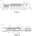
FIG. 7 is a front elevational view of the controller shown in FIG. 5;
FIG. 8 is a rear elevational view of the controller shown in FIG. 5;
FIG. 9 is a schematic view of a controller; and,
FIG. 10 is a flow chart of a method of controlling the ionizer system of FIG. 1.
DETAILED DESCRIPTION
At the outset, it should be appreciated that like drawing numbers on different drawing views identify identical, or functionally similar, structural elements. It is to be understood that the claims are not limited to the disclosed aspects.
Furthermore, it is understood that this disclosure is not limited to the particular methodology, materials and modifications described and as such may, of course, vary. It is also understood that the terminology used herein is for the purpose of describing particular aspects only, and is not intended to limit the scope of the claims.
Unless defined otherwise, all technical and scientific terms used herein have the same meaning as commonly understood to one of ordinary skill in the art to which this disclosure pertains. It should be understood that any methods, devices or materials similar or equivalent to those described herein can be used in the practice or testing of the example embodiments.
It should be appreciated that the term “substantially” is synonymous with terms such as “nearly,” “very nearly,” “about,” “approximately,” “around,” “bordering on,” “close to,” “essentially,” “in the neighborhood of,” “in the vicinity of,” etc., and such terms may be used interchangeably as appearing in the specification and claims. It should be appreciated that the term “proximate” is synonymous with terms such as “nearby,” “close,” “adjacent,” “neighboring,” “immediate,” “adjoining,” etc., and such terms may be used interchangeably as appearing in the specification and claims. The term “approximately” is intended to mean values within ten percent of the specified value.
Adverting now to the figures, FIG. 1 is a front perspective view of ionizer system 10. Ionizer system generally comprises sensor 50, controller 110, and at least one ionizer. In an example embodiment, ionizer system comprises whole room ionizer 20, individual ionizer 30, sensor 50, and controller 110. Whole room ionizer 20, individual ionizer 30, and sensor 50 are connected to controller 110 via electrical conduit 12. whole room ionizer 20, individual ionizer 30, and sensor 50 are also provided power through electrical conduit 12. However, it should be appreciated that whole room ionizer 20, individual ionizer 30, and sensor 50 may be connected to controller 110 via wireless communication, for example, Wi-Fi, Bluetooth technology, ZigBee, Infrared (IR), Radio, or any other suitable wireless communication method. In a wireless embodiment, whole room ionizer 20, individual ionizer 30, and sensor 50 would each have a suitable power source, for example, AC mains or battery. Controller 110 is capable of wirelessly communicating with remote computing device 40. Computing device 40 includes receiver 42 for receiving information from controller 110 and transmitter 44 for sending information to controller 110. Computing device 40 may also have a digital user interface.
Whole room ionizer 20 is a device that uses high voltage to ionize (electrically charge) air molecules. Whole room ionizer 20 is capable of generating negative ions, or anions, which are particles with one or more extra electron, conferring a net negative charge to the particle. Whole room ionizer 20 is also capable of generating positive ions, or cations, which are ions missing one or more electrons, resulting in a net positive charge. Whole room ionizer 20 may comprise a fan physically built therein. As ions are generated, the fan distributes the ions throughout the room or space. Whole room ionizer 20 is connected to controller 110 via electrical conduit 12. Whole room ionizer 20 is generally in communication with sensor 50. Specifically, whole room ionizer 20 receives instructions from controller 110 to distribute more negative ions and/or positive ions throughout the space or room. In an example embodiment, whole room ionizer 20 comprises receiver 22 and receives instructions from controller 110 via wireless transmission, without the need for physical electrical connection therebetween. It should be appreciated that ionizer system 10 may have any number of whole room ionizers to provide suitable ionization for the environment. For example, ionizer system 10 may have one or more whole room ionizers arranged thereon.
Individual ionizer 30 is a device that uses high voltage to ionize (electrically charge) air molecules. Individual ionizer 30 is capable of generating negative ions, or anions, which are particles with one or more extra electron, conferring a net negative charge to the particle. Individual ionizer 30 is also capable of generating positive ions, or cations, which are ions missing one or more electrons, resulting in a net positive charge. Individual ionizer 30 is preferably arranged on, or close in proximity to, machine 2. Individual ionizer 30 provides a higher concentration of ions directly around machine 2, whereas whole room ionizer 20 distributes ions generally to the entire space or room. Individual ionizer 30 may use compressed air to distribute ions, rather than a fan as in whole room ionizer 20. For example, as ions are generated, the compressed air distributes the ions directly around machine 2. In an example embodiment, individual ionizer 30 is connected to a compressor, which provides the compressed air. It should be appreciated that individual ionizer 30 may use a fan to distribute ions, and that whole room ionizer 20 may use compressed air to distribute ions. Individual ionizer 30 is connected to controller 110 via electrical conduit 12. Individual ionizer 30 is generally in communication with sensor 50. Specifically, individual ionizer 30 receives instructions from controller 110 to distribute more negative ions and/or positive ions throughout to and around machine 2. In an example embodiment, individual ionizer 30 comprises receiver 32 and receives instructions from controller 110 via wireless transmission, without the need for physical electrical connection therebetween. It should be appreciated that ionizer system 10 may have any number of individual ionizers to provide suitable ionization for the environment. For example, every machine may have one or more individual ionizers arranged thereon.
FIG. 2 is a top perspective view of sensor 50. FIG. 3 is an exploded view of sensor 50. FIG. 4 is a perspective view of circuit board assembly 96. Sensor 50 generally comprises housing 52, ion sensor 80, and circuit board assembly 96. Sensor 50 compares positive and negative ions in the space or room and sends that information to controller 110. The following description should be read in view of FIGS. 2-4.
Housing 52 is generally cylindrical and comprises end 54 and end 56. Housing 52 is preferably a conductive metal shielding that at least partially forms a Faraday shield around circuit board assembly 96, which is housed therein. A Faraday shield or Faraday cage (as discussed below) is an enclosure used to block electromagnetic fields. A Faraday shield may be formed by a continuous covering of conductive material or in the case of a Faraday cage, by a mesh of such materials. As such, housing 52 prevents interference with the sensitive circuitry of circuit board assembly 96. In an example embodiment, housing 52 comprises stainless steel. In an example embodiment, housing 52 comprises a plastic shell that is internally coated with a metal. End 54 comprises port 58. Sensor 50 is connected to controller 110 through port 58 via electrical conduit 12. In an example embodiment, port 58 is a RJ 45 connector. However, it should be appreciated that port 58 may comprise any connector suitable for providing an interface between sensor 50 and controller 110. In an example embodiment, sensor 50 communicates with controller 110 via transmitter 51.
Ion sensor 80 extends from housing 52. Ion sensor 80 comprises cage 86 and core 88, both extending between end 82, connected to end 56, and end 84. Ends 82 and 84 may comprise a conductive material, or may comprise plastic or other non-conductive material coated or wrapped in a conductive material such as copper foil. The material of ends 82 and 84 is such that it aids in creating a Faraday cage as discussed further below. Core 88 is a nonconductive core including two interleaved wire helices wrapped therearound. As shown in the figures, wires 92 and 94 are alternatingly wrapped around core 88, which are connected to circuit board assembly 96. Specifically, wire 92 is connected to circuit board 74 via any suitable method, for example, soldering. Wire 94 is connected to circuit board 60 via any suitable method, for example, soldering. One of wires 92 and 94 is charged to a voltage of approximately +35V and the other of wires 92 and 94 is charged to a voltage of approximately −35V. However, it should be appreciated that the precise voltage may be adjusted for various reasons, including adjusting sensitivity, calibration, or to accommodate specific requirements of the user. In an example embodiment, wire 92 comprises a positive charge and, when impacted by negative ions, gains electrons. Wire 92 is connected to circuit board 74 which comprises a transimpedance amplifier that converts this ion current into a voltage. Similarly, wire 94 comprises a negative charge and, when impacted by positive ions, loses electrons. Wire 94 is connected to circuit board 60 which comprises a transimpedance amplifier that converts this current to a voltage. It should be appreciated that in an example embodiment, wire 92 may comprise a negative charge and wire 94 may comprise a positive charge. These voltages are filtered, amplified, conditioned, and ultimately digitized by an ADC. The resulting digitized values are processed through proprietary algorithms to produce a result equivalent to the discharge time measured by a CPM. The measurements are also processed through a different proprietary algorithm to determine the DC balance of the ionizing system. If an uncharged CPM is placed in an ionizing stream, ideally, the plate would remain at zero volts with respect to ground, but many ionizers produce a slight imbalance in their ion streams, resulting in the charged plate monitor receiving a small positive or negative charge. This sensor technology can also measure this DC offset, essentially by comparing the results of the positive and negative helix currents. In an example embodiment, wires 92 and 94 are uninsulated, low corrosion, gold plated wires. The double-helix sensor design functions to provide real-time, direct measurement of ion current, and low noise/leakage.
Cage 86 is a metal (conductive) shield having openings 87 to allow airflow to core 88. Cage 86 forms a Faraday cage which protects wires 92 and 94 from electric fields that would otherwise affect the readings. Cage 86 is connected to the electrical ground plane of the sensor circuit boards, for example, an electrical ground plane (not shown) within circuit board 74, via wire 90. It should be appreciated that, cage 86 may be connected to an electrical ground plane located on circuit board 60 via wire 90. Furthermore, the electrical ground plane in circuit board 74 and the electrical ground plane in circuit board 60 are connected via one or more conductive pins, shown as pins 73A and 73B. Pins 73A and 73B extend from circuit board 60 to circuit board 74 to electrically connect the ground planes arranged in circuit board 60 and circuit board 74. The ground planes in circuit boards 60 and 74 help reduce the influence of external noise sources from interrupting the circuitry of circuit board assembly 96. The ground planes of the circuit boards keep sensitive analog circuits operating at low noise capability. It should be appreciated that any number of pins suitable for connecting the ground planes to reduce the external noise affecting the circuitry may be used. In an example embodiment, cage 86 is arranged as a mesh shield that attenuates external electromagnetic waves before they reach the double helix formed by wires 92 and 94, yet allows ions to flow therethrough. Openings 87 may comprise a square, hexagonal, circular, or irregular polygon geometry, or any other suitable geometry.
Circuit board assembly 96 generally comprises circuit board 60, circuit board 74, and circuit board 66, which are all connected to port 58. Circuit boards 60, 74, and 66 may be printed circuit boards (PCBs). Power inductor 68 is arranged between circuit board 66 and circuit board 74. However, power inductor 68 may be arranged at any suitable location relative to circuit boards 66 and 74. Circuit board 66 and power inductor 68 are arranged to regulate the power supplied to sensor 50. Circuit board 60 comprises inter alia, control relay 62, gain-control resistor 64, filter capacitor 63, and a transimpedance amplifier, and is connected to wire 94. Circuit board 60 is arranged to convert current in wire 94 to a voltage, and subsequently filter, amplify, condition, and digitize that voltage. Similarly, circuit board 74 comprises inter alia, control relay 76, gain-control resistor 78, filter capacitor 75, and a transimpedance amplifier, and is connected to wire 92. Circuit board 74 is arranged to convert current in wire 92 to a voltage, and subsequently filter, amplify, condition, and digitize that voltage. The digitized sets of data created by circuit boards 60 and/or 74 are then converted to a serial message format and transmitted via RS-485 (or another communication means) to controller 110. The level of DC balance determined by sensor 50 will be used by controller 110 to send information to an ionizer, adjusting it to ensure optimal protection against electrical charge buildup, as will be discussed in greater detail below.
FIG. 5 is a perspective view of controller 110, with a top portion of housing 112 removed for viewing purposes. FIG. 6 is a top elevational view of controller 110. FIG. 7 is a front elevational view of controller 110. FIG. 8 is a rear elevational view of controller 110 with housing 112 completely removed for viewing purposes. The following description should be read in view of FIGS. 5-8.
Controller 110 generally comprises housing 112 which protectively encloses circuit board 114 and data aggregator 138. Housing 112 comprises bottom portion 112A and top portion 112B (not shown). In an example embodiment, data aggregator 138 comprises a central processing unit (CPU).
Circuit board 114 comprises event detector port 116, ionizer port 118, sensor port 120, optional port 122, mode button 124, indicator lights 126 and 128, antenna port 130, power port 132, and optional communication or trigger port 134. Controller 110 is supplied power via power port 132. Mode button 124 allows a user to interact with controller 110. It should be appreciated that ports 116, 118, 120, and 122 are equivalent and interchangeable, and they also provide power to the peripherals. The peripherals announce to controller 110 what they are when they are plugged in. For example, if sensor 50 is plugged into port 118, the peripheral tells controller 110 to turn port 118 into a sensor port. The same detection means are included into each of the ports. It should be appreciated that controller 110 may have any suitable number of ports, and the instant invention is not limited to the number of ports illustrated in the figures.
Event detector port 116 is arranged to send a signal or signals to a remote location indicating that ionizer system 10 is not operating normally. If an error has occurred with controller 110, sensor 50, whole room ionizer 20, or individual ionizer 30, controller 110 sends a signal to indicate such (e.g., if an ionizer or sensor has been damaged). Controller 110 may also send a signal via event detector port 116 to a remote location to indicate the ionizer system 10 is operating normally. Similarly, indicator lights 126 and 128 are arranged for a visual indication of system status. In an example embodiment, indicator light 126 is red and indicator light 128 is green. When ionizer system 10 is operating normally, indicator light 128 is on and indicator light 126 is off. When an error has occurred in ionizer system 10, as discussed above, indicator light 126 is on and indicator light 128 is off. Indicator lights 126 and 128 are preferably light emitting diodes (LEDs); however, it should be appreciated that indicator lights 126 and 128 may be any other suitable light source and any colors suitable for indicating the status of ionizer system 10. In an example embodiment, indicator lights 126 and 128 are red/green/blue LEDs and can indicate any color of the visible spectrum. In an example embodiment, controller 110 comprises a speaker and indicates that an error has occurred in ionizing system 10 via an alarm or other suitable noise (e.g., a siren). In an example embodiment, the colors indicated by indicator lights 126 and 128 could change back and for the depending on ion balance. In an example embodiment, the colors indicated by indicator lights 126 and 128 could show ion strength in a thermometer-style display.
Ionizer port 118 is arranged to physically connect one or more ionizers to controller 110. For example, whole room ionizer 20 and/or individual ionizer 30 are connected to controller 110 via ionizer port 118. It should be appreciated that controller 110 may have one or more ionizer ports, and that the embodiment shown is not limited to only one ionizer port. In an example embodiment, controller 110 comprises a separate ionizer port for each ionizer in ionizer system 10. Controller 110 may control all of the ionizers in ionizer system 10 together. For example, if controller 110 receives a signal from sensor 50 that ionizer system 10 needs more positive ions, controller 110 sends a signal to all of the ionizers to produce more positive ions. Controller 110 may control each of the ionizers in ionizer system 10 separately. For example, if controller 110 receives a signal from sensor 50 that machine 2 needs more positive ions, controller 110 sends a signal to only the individual ionizer 30, and not to whole room ionizer 20, to produce more positive ions.
Sensor port 120 is arranged to physically connect one or more sensors to controller 110. For example, sensor 50 is connected to controller 110 via sensor port 120. It should be appreciated that controller 110 may have one or more sensor ports, and that the embodiment shown is not limited to only one sensor port. In an example embodiment, controller 110 comprises a separate sensor port for each sensor in ionizer system 10. Controller 110 may receive information from all of the sensors in ionizer system 10 together. For example, if controller 110 receives a signal from one sensor that ionizer system 10 needs more positive ions, controller 110 sends a signal to all of the ionizers to produce more positive ions. Controller 110 may receive information from each of the sensors in ionizer system 10 individually and locationally. For example, if controller 110 receives a signal from sensor 50 that machine 2 needs more positive ions, controller 110 sends a signal to only the individual ionizer 30, and not to whole room ionizer 20, to produce more positive ions. In an example embodiment, sensor port 120 comprises a built in boot loader for programming controller 110, specifically circuit board 114.
Antenna port 130 is arranged to physically connect the transducer in controller 110 to an external transmitter or antenna, or an external transmitter having an antenna, either directly or through an extension cable. Specifically, antenna port 130 is arranged to connect to a transmission device or antenna, or a transmission device having an antenna, to transmit information wirelessly to receiver 42 of computing device 40. In an example embodiment, a transmission device may be built directly into controller 110 as will be discussed below. However, antenna port 130 allows for connection to a transmission device that is, for example, outside of the Faraday cage in which controller 110 is located.
Aggregator 138 comprises programming port 136, Universal Serial Bus (USB) ports 140, audio/composite video port 142, High-Definition Multimedia Interface (HDMI) port 144, and micro Universal Serial Bus (USB) port 146. Aggregator 138 is arranged a hardware device engineered to extract real-time intersection and traffic cabinet data from interconnected or non-interconnected intersections. In an example embodiment, aggregator 138 is a subassembly of controller 110 having a CPU and used as an optional controller.
Controller 110 stores some data short-term (i.e., via aggregator 138) and feeds the information via a network protocol (e.g., Wi-Fi, Ethernet, or any other suitable means) to computing device 40, which handles long-term storage of the measurements. A user interface, initially a web browser in a computer, tablet, or mobile device, provides measurements, graphs, and alerts to the user. Cloud connectivity is also an option, enabling enterprise-wide monitoring. Connectivity to other process automation software and hardware will allow improved process control and product manufacturing monitoring, enabling traceability of a particular item back to each manufacturing step, and a log of how effective the anti-static measures were.
Controller 110 receives information from sensor 50, for example, that there is an imbalance in positive and negative ions. Controller 110 then sends a signal to whole room ionizer 20 and/or individual ionizer 30 to produce either positive or negative ions, whichever are needed. Sensor 50 then sends a signal to controller 110 when there is a balance in positive and negative ions. Controller 110 then sends a signal to whole room ionizer 20 and individual ionizer 30 to stop producing ions or maintain the present ratio. Controller 110 sends information to computing device 40 which is arranged to log data. For example, data may collected regarding the length of time the ionizers run in order to balance the ions in the space or room. If the ionizers need to run for 45 minutes while producing negative ions, but only need to run for 10 minutes while producing positive ions, this may be an indication that the ionizers are not producing negative ions as efficiently as they should be. Additionally or alternatively, this may be an indication that something in the space or room (e.g., a machine) is causing the significant imbalance of positive ions to negative ions, which is resulting in the need for significantly more negative ions. The real-time monitoring and data logging capabilities of ionizer system 10, specifically through the use of sensor 50, allows the efficiencies of the ionizers to be determined quickly and effectively, and allows deficiencies in machines or abnormalities in the environment to be detected.
FIG. 9 is a schematic view of controller 210. Controller 210 generally comprises housing 212 which protectively encloses circuit board 214, data aggregator 238, receiver 250, and transmitter 252. Housing 212 comprises bottom portion 212A and top portion 212B (not shown). Receiver 250 receives information wirelessly from a remote location, e.g., computing device 40. Receiver 250 allows controller 210 to be programmed wirelessly and remotely. Transmitter 252 allows controller 210 to send information wirelessly to a remote location, e.g., computing device 40. Transmitter 252 may be a replacement for, or additional component to, antenna port 230.
Circuit board 214 comprises event detector port 216, ionizer port 218, sensor port 220, optional port 222, mode button 224, indicator lights 226 and 228, antenna port 230, power port 232, and optional communication or trigger port 234. Controller 210 is supplied power via power port 232. Mode button 224 allows a user to interact with controller 210. It should be appreciated that the various ports are interchangeable and not dedicated to a specific location. Additionally, the various ports can be rededicated to provide for other uses.
Event detector port 216 is arranged to send a signal or signals to a remote location indicating that ionizer system 10 is not operating normally. If an error has occurred with controller 210, sensor 50, whole room ionizer 20, or individual ionizer 30, controller 210 sends a signal to indicate such (e.g., if an ionizer or sensor has been damaged). Controller 210 may also send a signal via event detector port 216 to a remote location to indicate the ionizer system 10 is operating normally. Similarly, indicator lights 226 and 228 are arranged for a visual indication of system status. In an example embodiment, indicator light 226 is red and indicator light 228. When ionizer system 10 is operating normally, indicator light 228 is on and indicator light 226 is off. When an error has occurred in ionizer system 10, as discussed above, indicator light 226 is on and indicator light 228 is off. Indicator lights 226 and 228 are preferably light emitting diodes (LEDs); however, it should be appreciated that indicator lights 226 and 228 may be any other suitable light source and any colors suitable for indicating the status of ionizer system 10. In an example embodiment, controller 210 comprises a speaker and indicates that an error has occurred in ionizing system 10 via an alarm or other suitable noise.
Ionizer port 218 is arranged to physically connect one or more ionizers to controller 210. For example, whole room ionizer 20 and/or individual ionizer 30 are connected to controller 210 via ionizer port 218. It should be appreciated that controller 210 may have one or more ionizer ports, and that the embodiment shown is not limited to only one ionizer port. In an example embodiment, controller 210 comprises a separate ionizer port for each ionizer in ionizer system 10. Controller 210 may control all of the ionizers in ionizer system 10 together. For example, if controller 210 receives a signal from sensor 50 that ionizer system 10 needs more positive ions, controller 210 sends a signal to all of the ionizers to produce more positive ions. Controller 210 may control each of the ionizers in ionizer system 10 separately. For example, if controller 210 receives a signal from sensor 50 that machine 2 needs more positive ions, controller 210 sends a signal to only the individual ionizer 30, and not to whole room ionizer 20, to produce more positive ions.
Sensor port 220 is arranged to physically connect one or more sensors to controller 210. For example, sensor 50 is connected to controller 210 via sensor port 220. It should be appreciated that controller 210 may have one or more sensor ports, and that the embodiment shown is not limited to only one sensor port. In an example embodiment, controller 210 comprises a separate sensor port for each sensor in ionizer system 10. Controller 210 may receive information from all of the sensors in ionizer system 10 together. For example, if controller 210 receives a signal from one sensor that ionizer system 10 needs more positive ions, controller 210 sends a signal to all of the ionizers to produce more positive ions. Controller 210 may receive information from each of the sensors in ionizer system 10 individually and locationally. For example, if controller 210 receives a signal from sensor 50 that machine 2 needs more positive ions, controller 210 sends a signal to only the individual ionizer 30, and not to whole room ionizer 20, to produce more positive ions. In an example embodiment, sensor port 220 comprises a built in boot loader for programming controller 210, specifically circuit board 214.
Antenna port 230 is arranged to physically connect controller 210 to a transmitter. Specifically, antenna port 230 is arranged to connect to a transmission device to transmit information wirelessly to receiver 42 of computing device 40. In an example embodiment, a transmission device may be built directly into controller 210 as will be discussed below. However, antenna port 230 allows for connection to a transmission device that is, for example, outside of the Faraday cage in which controller 210 is located. In an example embodiment, receiver 250 and transmitter 252 are both connected to antenna port 230, and antenna port is connected to a transmitter or an antenna, or a transmitter having an antenna, directly or via an extension cable.
Aggregator 238 comprises programming port 236, Universal Serial Bus (USB) ports 240, audio/composite video port 242, High-Definition Multimedia Interface (HDMI) port 244, and micro Universal Serial Bus (USB) port 246. Aggregator 238 is arranged a hardware device engineered to extract real-time intersection and traffic cabinet data from interconnected or non-interconnected intersections.
Controller 210 stores some data short-term (i.e., via aggregator 238) and feeds the information via a network protocol (e.g., Wi-Fi, Ethernet, or any other suitable means) to computing device 40, which handles long-term storage of the measurements. A user interface, initially a web browser in a computer, tablet, or mobile device, provides measurements, graphs, and alerts to the user. Cloud connectivity is also an option, enabling enterprise-wide monitoring. Connectivity to other process automation software and hardware will allow improved process control and product manufacturing monitoring, enabling traceability of a particular item back to each manufacturing step, and a log of how effective the anti-static measures were.
Controller 210 receives information from sensor 50, for example, that there is an imbalance in positive and negative ions. Controller 210 then sends a signal to whole room ionizer 20 and/or individual ionizer 30 to produce either positive or negative ions, whichever are needed. Sensor 50 then sends a signal to controller 210 when there is a balance in positive and negative ions. Controller 210 then sends a signal to whole room ionizer 20 and individual ionizer 30 to stop producing ions. Controller 210 sends information to computing device 40 which is arranged to log data. For example, data may collected regarding the length of time the ionizers run in order to balance the ions in the space or room. If the ionizers need to run for 45 minutes while producing negative ions, but only need to run for 10 minutes while producing positive ions, this may be an indication that the ionizers are not producing negative ions as efficiently as they should be. Additionally or alternatively, this may be an indication that something in the space or room (e.g., a machine) is causing the significant imbalance of positive ions to negative ions, which is resulting in the need for significantly more negative ions. The real-time monitoring and data logging capabilities of ionizer system 10, specifically through the use of sensor 50, allows the efficiencies of the ionizers to be determined quickly and effectively, and allows deficiencies in machines to be detected.
FIG. 10 shows flow chart 300 outlining a method of controlling ionizer system 10. The method is performed by controller 110, which is in communication with whole room ionizer 20, individual ionizer 30, senor 50, and remote computing device 40.
In step 302, controller 50 receives a set of data from sensor 50. The data may be received via electrical conduit 12 (i.e., hardwired connection) or via a wireless transmission sent by transmitter 51 (i.e., wireless connection).
In step 304, controller 50 determines if there is an ion imbalance in the space or room. For example, if the level of positive ions is equal to the level of negative ions, then there is no ion imbalance. If the level of positive ions is not equal to the level of negative ions, then there is an ion imbalance.
If there is no ion imbalance, then in step 316, controller 50 sends a communication to remote computing device 40. Computing device 40 logs this communication (i.e., at that particular moment in time there was no ion imbalance). Additionally, if there is no ion imbalance, controller 50 may send a signal to whole room ionizer 20 and/or individual ionizer 30 to produce a balanced quantity of positive and negative ions.
If there is an ion imbalance, then in step 306, controller 50 determines if more positive ions are needed. If the level of positive ions is less than the level of negative ions, then more positive ions are needed. If the level of positive ions is greater than or equal to the level of negative ions, then more positive ions are not needed.
If more positive ions are needed, then in step 308, controller 50 sends a signal to whole room ionizer 20 and/or individual ionizer 30 to produce positive ions.
If more positive ions are not needed, then in step 310, controller 50 determines if more negative ions are needed. If the level of negative ions is less than the level of positive ions, then more negative ions are needed. If the level of negative ions is greater than or equal to the level of positive ions, then more negative ions are not needed. It should be appreciated that this step may be removed from the method because, if controller 50 determines that there is an ion imbalance in step 304, and also determines that more positive ions are not needed in step 306, then by logic more negative ions must be needed.
If more negative ions are needed, then in step 312, controller 50 sends a signal to whole room ionizer 20 and/or individual ionizer 30 to produce negative ions.
If more negative ions are not needed, then in step 314, controller 50 sends a signal that an error in ionizer system 10 has occurred. Controller 50 may, for example, send a signal to a remote location through event detector port 116 and/or indicate a system error via indicator lights 126/128.
After controller 50 has sent a signal either in step 308, step 312, or step 314, controller sends a communication to computing device 40. Computing device 40 logs the communication. The data that is logged by computing device 40 can then be analyzed and compiled to determine the efficiency of the ionizers, the calibration of the sensors, and any defects in the system producing an excessive charge in the space or room (e.g., a faulty machine).
It should be appreciated that there are various methods of increasing the level of positive ions relative to negative ions and also increasing the level of negative ions relative to positive ions. For example, if more negative ions are needed, controller 50 may stop the production of positive ions and continue to produce negative ions, reduce the production of positive ions and continue to produce negative ions, stop the production of positive ions and increase the production of negative ions, or reduce the production of positive ions and increase the production of negative ions. If more positive ions are needed, controller 50 may stop the production of negative ions and continue to produce positive ions, reduce the production of negative ions and continue to produce positive ions, stop the production of negative ions and increase the production of positive ions, or reduce the production of negative ions and increase the production of positive ions.
It will be appreciated that various aspects of the disclosure above and other features and functions, or alternatives thereof, may be desirably combined into many other different systems or applications. Various presently unforeseen or unanticipated alternatives, modifications, variations, or improvements therein may be subsequently made by those skilled in the art which are also intended to be encompassed by the following claims.
LIST OF REFERENCE NUMERALS
  • 2 Machine
  • 10 Ionizer system
  • 12 Electrical conduit
  • 20 Whole room ionizer
  • 22 Receiver
  • 30 Individual ionizer
  • 32 Receiver
  • 40 Computing device
  • 42 Receiver
  • 44 Transmitter
  • 50 Sensor
  • 51 Transmitter
  • 52 Housing
  • 54 End
  • 56 End
  • 58 Port
  • 60 Circuit board
  • 62 Control relay
  • 63 Filter capacitor
  • 64 Gain-control resistor
  • 66 Circuit board
  • 68 Power Inductor
  • 70 Capacitor
  • 72 Capacitor
  • 73A Pin
  • 73B Pin
  • 74 Circuit board
  • 75 Filter capacitor
  • 76 Control relay
  • 78 Gain-control resistor
  • 80 Ion sensor
  • 82 End
  • 84 End
  • 86 Cage
  • 87 Openings
  • 88 Core
  • 90 Wire
  • 92 Wire
  • 94 Wire
  • 96 Circuit board assembly
  • 110 Controller
  • 112 Housing
  • 112A Bottom portion
  • 112B Top portion (not shown)
  • 114 Circuit board
  • 116 Event detector port
  • 118 Ionizer port
  • 120 Sensor port
  • 122 Optional port
  • 124 Mode button
  • 126 Indicator light
  • 128 Indicator light
  • 130 Antenna port
  • 132 Power port
  • 134 Optional communication port
  • 136 Programming port
  • 138 Data aggregator
  • 140 Universal Serial Bus (USB) ports
  • 142 Audio/composite video port
  • 144 High-Definition Multimedia Interface (HDMI) port
  • 146 Micro Universal Serial Bus (USB) port
  • 210 Controller
  • 212 Housing
  • 212A Bottom portion
  • 212B Top portion
  • 214 Circuit board
  • 216 Event detector port
  • 218 Ionizer port
  • 220 Sensor port
  • 222 Optional port
  • 224 Mode button
  • 226 Indicator light
  • 228 Indicator light
  • 230 Antenna port
  • 232 Power port
  • 234 Optional communication port
  • 236 Programming port
  • 238 Data aggregator
  • 240 Universal Serial Bus (USB) ports
  • 242 Audio/composite video port
  • 244 High-Definition Multimedia Interface (HDMI) port
  • 246 Micro Universal Serial Bus (USB) port
  • 250 Receiver
  • 252 Transmitter
  • 300 Flow chart
  • 302 Step
  • 304 Step
  • 306 Step
  • 308 Step
  • 310 Step
  • 312 Step
  • 314 Step
  • 316 Step

Claims (12)

What is claimed is:
1. An ionizer system, comprising:
a controller, comprising:
an event detector port;
an ionizer port arranged to connect the at least one ionizer to the controller;
a sensor port arranged to connect the at least one sensor to the controller;
an antenna port arranged to connect the controller to a transmitter;
at least one indicator light;
at least one sensor connected to the controller, the at least one sensor including:
a first circuit board assembly;
a core;
a cage at least partially surrounding the core;
a first wire connected to the first circuit board assembly;
a second wire connected to the first circuit board assembly; and,
a third wire connecting the cage to the first circuit board assembly; and,
at least one ionizer connected to the controller.
2. The ionizer system as recited in claim 1, wherein the sensor further comprises a housing at least partially enclosing the first circuit board assembly, the housing including a first end and a second end.
3. The ionizer system as recited in claim 2, wherein the sensor further comprises a port connected to the first circuit board assembly, the port arranged proximate the first end.
4. The ionizer system as recited in claim 3, wherein the core and the cage extend from the second end.
5. The ionizer system as recited in claim 1, wherein the controller further comprises
a second circuit board assembly.
6. The ionizer system as recited in claim 5, wherein the controller further comprises
a power port.
7. The ionizer system as recited in claim 6, wherein the controller is operatively arranged to communicate with a remote computing device via the antenna port.
8. The ionizer system as recited in claim 5, wherein the controller further comprises a data aggregator.
9. The ionizer system as recited in claim 5, wherein the controller further comprises a transmitter and a receiver for wirelessly communicating with a remote computing device.
10. The ionizer system as recited in claim 1, wherein the at least one sensor and the at least one ionizer are connected to the controller wirelessly.
11. A method of monitoring an ionizing system, the method comprising:
receiving a first set of data from at least one sensor of an ion imbalance;
making a first determination, based on the first set of data, whether positive ions or negative ions are needed;
sending a first signal, based on the first determination, to at least one ionizer to produce the positive ions or negative ions;
sending a first communication about the first determination and the first signal to a remote computing device;
receiving a second set of data from the at least one sensor of an ion balance;
making a second determination, based on the second set of data, that no positive ions or negative ions are needed;
sending a second signal, based on the second determination, to the at least one ionizer to stop producing positive and negative ions; and,
sending a second communication about the second determination and the second signal to the remote computing device.
12. An ionizer system, comprising:
a controller, comprising:
a plurality of ports;
at least one indicator light; and,
a first circuit board assembly;
at least one sensor connected to the controller, the at least one sensor including:
a second circuit board assembly;
a core;
a cage at least partially surrounding the core;
a first wire extending into the core and connected to the second circuit board assembly;
a second wire extending into the core and connected to the second circuit board assembly; and,
a third wire connecting the cage to the second circuit board assembly; and,
at least one ionizer connected to the controller.
US15/954,041 2018-04-16 2018-04-16 Ionizer monitoring system and ion sensor Active 2039-03-27 US10794863B1 (en)

Priority Applications (2)

Application Number Priority Date Filing Date Title
US15/954,041 US10794863B1 (en) 2018-04-16 2018-04-16 Ionizer monitoring system and ion sensor
US16/126,157 US10859531B2 (en) 2018-04-16 2018-09-10 Ionizer monitoring system and ion sensor

Applications Claiming Priority (1)

Application Number Priority Date Filing Date Title
US15/954,041 US10794863B1 (en) 2018-04-16 2018-04-16 Ionizer monitoring system and ion sensor

Related Child Applications (1)

Application Number Title Priority Date Filing Date
US16/126,157 Continuation-In-Part US10859531B2 (en) 2018-04-16 2018-09-10 Ionizer monitoring system and ion sensor

Publications (1)

Publication Number Publication Date
US10794863B1 true US10794863B1 (en) 2020-10-06

Family

ID=72664127

Family Applications (1)

Application Number Title Priority Date Filing Date
US15/954,041 Active 2039-03-27 US10794863B1 (en) 2018-04-16 2018-04-16 Ionizer monitoring system and ion sensor

Country Status (1)

Country Link
US (1) US10794863B1 (en)

Citations (24)

* Cited by examiner, † Cited by third party
Publication number Priority date Publication date Assignee Title
US4477263A (en) 1982-06-28 1984-10-16 Shaver John D Apparatus and method for neutralizing static electric charges in sensitive manufacturing areas
US4542434A (en) 1984-02-17 1985-09-17 Ion Systems, Inc. Method and apparatus for sequenced bipolar air ionization
US4809127A (en) 1987-08-11 1989-02-28 Ion Systems, Inc. Self-regulating air ionizing apparatus
US4901194A (en) * 1988-07-20 1990-02-13 Ion Systems, Inc. Method and apparatus for regulating air ionization
US4974115A (en) 1988-11-01 1990-11-27 Semtronics Corporation Ionization system
US5047892A (en) * 1989-03-07 1991-09-10 Takasago Thermal Engineering Co., Ltd. Apparatus for removing static electricity from charged articles existing in clean space
US6052053A (en) 1997-10-22 2000-04-18 Semtronics Corporation Continuous monitoring system
US6078875A (en) 1997-08-20 2000-06-20 Semtronics Corporation Automated auditing system
US6252233B1 (en) 1998-09-18 2001-06-26 Illinois Tool Works Inc. Instantaneous balance control scheme for ionizer
US20030218855A1 (en) * 2002-05-22 2003-11-27 Semtronics Ionization system with reduced power supply
US20040145852A1 (en) * 2003-01-29 2004-07-29 Credence Technologies Inc. Method and device for controlling ionization
US6781811B2 (en) 2002-03-01 2004-08-24 Hugle Electronics Incorporated Ionizer control system
US6785114B2 (en) * 2001-03-29 2004-08-31 Illinois Tool Works Inc. Foraminous filter for use in air ionizer
US20050031503A1 (en) 2003-08-05 2005-02-10 Fox Michael T. Air ionization control
US20050063130A1 (en) * 2003-09-22 2005-03-24 Christopher Francis Electrical ionizer
US20060002051A1 (en) * 2004-07-01 2006-01-05 Goudy Paul R Jr Electric discharge apparatus and method for ionizing fluid and method of deodorizing and eliminating mold
US20090053989A1 (en) 2005-04-06 2009-02-26 Tom Lunde Interior Air Quality Space and Methods of Designing and Constructing Same
CN201668763U (en) 2010-04-14 2010-12-15 深圳市玖木科技发展有限公司 Negative ion super-oxygen ceiling type or wall hung type air purifying machine
US20110032496A1 (en) * 2009-08-07 2011-02-10 Nikon Corporation Movable body apparatus, exposure apparatus, exposure method, and device manufacturing method
US7924544B2 (en) 1998-09-18 2011-04-12 Illinois Tool Works Inc. Low voltage modular room ionization system
US20110274228A1 (en) * 2010-05-04 2011-11-10 Lopez Jose E Nuclear fusion using electrostatic cage and electro-magnetic field
US20130271164A1 (en) * 2010-12-07 2013-10-17 3M Innovative Properties Company Ionization Balance Device With Shielded Capacitor Circuit For Ion Balance Measurements and Adjustments
US20150336109A1 (en) * 2014-05-20 2015-11-26 Illinois Tool Works Inc. Wire electrode cleaning in ionizing blowers
US9404945B2 (en) 2011-12-08 2016-08-02 Desco Industries, Inc. Ionization monitoring device

Patent Citations (26)

* Cited by examiner, † Cited by third party
Publication number Priority date Publication date Assignee Title
US4477263A (en) 1982-06-28 1984-10-16 Shaver John D Apparatus and method for neutralizing static electric charges in sensitive manufacturing areas
US4542434A (en) 1984-02-17 1985-09-17 Ion Systems, Inc. Method and apparatus for sequenced bipolar air ionization
US4809127A (en) 1987-08-11 1989-02-28 Ion Systems, Inc. Self-regulating air ionizing apparatus
US4901194A (en) * 1988-07-20 1990-02-13 Ion Systems, Inc. Method and apparatus for regulating air ionization
US4951172A (en) 1988-07-20 1990-08-21 Ion Systems, Inc. Method and apparatus for regulating air ionization
US4974115A (en) 1988-11-01 1990-11-27 Semtronics Corporation Ionization system
US5047892A (en) * 1989-03-07 1991-09-10 Takasago Thermal Engineering Co., Ltd. Apparatus for removing static electricity from charged articles existing in clean space
US6078875A (en) 1997-08-20 2000-06-20 Semtronics Corporation Automated auditing system
US6052053A (en) 1997-10-22 2000-04-18 Semtronics Corporation Continuous monitoring system
US6252233B1 (en) 1998-09-18 2001-06-26 Illinois Tool Works Inc. Instantaneous balance control scheme for ionizer
US8861166B2 (en) 1998-09-18 2014-10-14 Illinois Tool Works, Inc. Low voltage modular room ionization system
US7924544B2 (en) 1998-09-18 2011-04-12 Illinois Tool Works Inc. Low voltage modular room ionization system
US6785114B2 (en) * 2001-03-29 2004-08-31 Illinois Tool Works Inc. Foraminous filter for use in air ionizer
US6781811B2 (en) 2002-03-01 2004-08-24 Hugle Electronics Incorporated Ionizer control system
US20030218855A1 (en) * 2002-05-22 2003-11-27 Semtronics Ionization system with reduced power supply
US20040145852A1 (en) * 2003-01-29 2004-07-29 Credence Technologies Inc. Method and device for controlling ionization
US20050031503A1 (en) 2003-08-05 2005-02-10 Fox Michael T. Air ionization control
US20050063130A1 (en) * 2003-09-22 2005-03-24 Christopher Francis Electrical ionizer
US20060002051A1 (en) * 2004-07-01 2006-01-05 Goudy Paul R Jr Electric discharge apparatus and method for ionizing fluid and method of deodorizing and eliminating mold
US20090053989A1 (en) 2005-04-06 2009-02-26 Tom Lunde Interior Air Quality Space and Methods of Designing and Constructing Same
US20110032496A1 (en) * 2009-08-07 2011-02-10 Nikon Corporation Movable body apparatus, exposure apparatus, exposure method, and device manufacturing method
CN201668763U (en) 2010-04-14 2010-12-15 深圳市玖木科技发展有限公司 Negative ion super-oxygen ceiling type or wall hung type air purifying machine
US20110274228A1 (en) * 2010-05-04 2011-11-10 Lopez Jose E Nuclear fusion using electrostatic cage and electro-magnetic field
US20130271164A1 (en) * 2010-12-07 2013-10-17 3M Innovative Properties Company Ionization Balance Device With Shielded Capacitor Circuit For Ion Balance Measurements and Adjustments
US9404945B2 (en) 2011-12-08 2016-08-02 Desco Industries, Inc. Ionization monitoring device
US20150336109A1 (en) * 2014-05-20 2015-11-26 Illinois Tool Works Inc. Wire electrode cleaning in ionizing blowers

Similar Documents

Publication Publication Date Title
US10073055B2 (en) Ion detector for measuring ion output
EP0987929A2 (en) Ionization system
ES2726808T3 (en) Leakage current sensor for pole type insulator
KR101769673B1 (en) Monitoring system of electromagnetic wave and grounding resistance
EP3400632B1 (en) Electrical connector plug continuity
EP3620786B1 (en) Ion sensor
WO2014136121A1 (en) Vibrating screen panel health monitoring system
JP2008519260A (en) Ion balance monitor
US10794863B1 (en) Ionizer monitoring system and ion sensor
US10859531B2 (en) Ionizer monitoring system and ion sensor
EP1142073B1 (en) Self-balancing ionizer monitor
JP2012213270A (en) Non-contact power supply system
JP2018198933A (en) Testing of defibrillator electrodes
US20090027057A1 (en) Ethernet Electrometer
CN105242126B (en) A kind of high orbit satellite static discharge monitoring device
CN209656791U (en) It is a kind of building or structures electrostatic detection system
CN210571032U (en) Thermal disaster detection device for limited space
KR102028760B1 (en) Portable partial discharge monitoring apparatus and method
KR200462724Y1 (en) Device for alarming overcurrent for electric power supply terminal
KR20120133946A (en) Earth ring observation device and earth ring monitoring system
US20090020969A1 (en) Wheeled moving body and grounding condition monitoring apparatus for the same
TWI642948B (en) Electrostatic monitoring system
CN111381098A (en) High-voltage display early warning system for static electricity removing device
CN208110657U (en) Medical device parameters acquisition system
CN219922432U (en) Filter device and component carrier manufacturing apparatus

Legal Events

Date Code Title Description
FEPP Fee payment procedure

Free format text: ENTITY STATUS SET TO UNDISCOUNTED (ORIGINAL EVENT CODE: BIG.); ENTITY STATUS OF PATENT OWNER: SMALL ENTITY

FEPP Fee payment procedure

Free format text: ENTITY STATUS SET TO SMALL (ORIGINAL EVENT CODE: SMAL); ENTITY STATUS OF PATENT OWNER: SMALL ENTITY

STCF Information on status: patent grant

Free format text: PATENTED CASE

FEPP Fee payment procedure

Free format text: SURCHARGE FOR LATE PAYMENT, SMALL ENTITY (ORIGINAL EVENT CODE: M2554); ENTITY STATUS OF PATENT OWNER: SMALL ENTITY

MAFP Maintenance fee payment

Free format text: PAYMENT OF MAINTENANCE FEE, 4TH YR, SMALL ENTITY (ORIGINAL EVENT CODE: M2551); ENTITY STATUS OF PATENT OWNER: SMALL ENTITY

Year of fee payment: 4