EP1067294A2 - Filterumleitung eines hydraulischen Systems - Google Patents
Filterumleitung eines hydraulischen Systems Download PDFInfo
- Publication number
- EP1067294A2 EP1067294A2 EP00113963A EP00113963A EP1067294A2 EP 1067294 A2 EP1067294 A2 EP 1067294A2 EP 00113963 A EP00113963 A EP 00113963A EP 00113963 A EP00113963 A EP 00113963A EP 1067294 A2 EP1067294 A2 EP 1067294A2
- Authority
- EP
- European Patent Office
- Prior art keywords
- hydraulic fluid
- temperature
- pump
- consumers
- filter unit
- Prior art date
- Legal status (The legal status is an assumption and is not a legal conclusion. Google has not performed a legal analysis and makes no representation as to the accuracy of the status listed.)
- Withdrawn
Links
- 239000012530 fluid Substances 0.000 claims abstract description 56
- 230000001419 dependent effect Effects 0.000 claims description 22
- 238000001914 filtration Methods 0.000 claims description 13
- 230000005540 biological transmission Effects 0.000 claims description 4
- 230000000694 effects Effects 0.000 claims 1
- 238000011144 upstream manufacturing Methods 0.000 claims 1
- 230000002706 hydrostatic effect Effects 0.000 description 3
- 238000011109 contamination Methods 0.000 description 2
- 239000004020 conductor Substances 0.000 description 1
- 230000008602 contraction Effects 0.000 description 1
- 210000003746 feather Anatomy 0.000 description 1
- 238000010438 heat treatment Methods 0.000 description 1
- 238000005461 lubrication Methods 0.000 description 1
- 239000000463 material Substances 0.000 description 1
Images
Classifications
-
- F—MECHANICAL ENGINEERING; LIGHTING; HEATING; WEAPONS; BLASTING
- F15—FLUID-PRESSURE ACTUATORS; HYDRAULICS OR PNEUMATICS IN GENERAL
- F15B—SYSTEMS ACTING BY MEANS OF FLUIDS IN GENERAL; FLUID-PRESSURE ACTUATORS, e.g. SERVOMOTORS; DETAILS OF FLUID-PRESSURE SYSTEMS, NOT OTHERWISE PROVIDED FOR
- F15B21/00—Common features of fluid actuator systems; Fluid-pressure actuator systems or details thereof, not covered by any other group of this subclass
- F15B21/04—Special measures taken in connection with the properties of the fluid
- F15B21/045—Compensating for variations in viscosity or temperature
-
- F—MECHANICAL ENGINEERING; LIGHTING; HEATING; WEAPONS; BLASTING
- F15—FLUID-PRESSURE ACTUATORS; HYDRAULICS OR PNEUMATICS IN GENERAL
- F15B—SYSTEMS ACTING BY MEANS OF FLUIDS IN GENERAL; FLUID-PRESSURE ACTUATORS, e.g. SERVOMOTORS; DETAILS OF FLUID-PRESSURE SYSTEMS, NOT OTHERWISE PROVIDED FOR
- F15B21/00—Common features of fluid actuator systems; Fluid-pressure actuator systems or details thereof, not covered by any other group of this subclass
- F15B21/04—Special measures taken in connection with the properties of the fluid
- F15B21/041—Removal or measurement of solid or liquid contamination, e.g. filtering
Definitions
- the invention relates to a hydraulic system for Filtering of hydraulic fluid according to the generic term of Claim 1.
- Such systems for filtering hydraulic fluid are often used in drives which are hydraulic Have consumers as well as pumps or hydraulic controls, which, in order to ensure the function, a certain one Need purity of the hydraulic fluid.
- a pump both a hydraulic control and the hydrostatic unit and the lubrication of the transmission takes over need in the start-up state with still cold Hydraulic fluid sufficient pressure and amount of hydraulic fluid, to supply consumers and a specific one Purity of the hydraulic fluid, which is necessary when operating the actuator at operating temperature is necessary because at this The viscosity of the hydraulic fluid is lower and is therefore a contamination of the hydraulic fluid May cause more harm to consumers.
- DE 195 39 759 A1 discloses a hydraulic system for filtering hydraulic fluid, in which a Pump delivers hydraulic fluid to a filter, whereby this Filter is biased with a spring element. Increases due to increased viscosity of the hydraulic fluid, the flow resistance the hydraulic fluid through the filter, so the pressure in front of the filter element increases and exceeds this pressure a certain value, which by the spring element is set, the hydraulic fluid on Filter element flow past directly to consumers. This ensures that in the start-up state with cold hydraulic fluid sufficient pressure and quantity Will be available to consumers, however, if contaminated the flow resistance of the filter element Filter element increased so that even at operating temperature with lower viscosity of the hydraulic fluid the hydraulic fluid is no longer filtered.
- the present invention is based on the object a hydraulic system for filtering hydraulic fluid to create, in which when starting with cold hydraulic fluid sufficient pressure and volume for consumers is provided and when operating at operating temperature the filtering of the hydraulic fluid is guaranteed is.
- a pump delivers hydraulic fluid a filter unit and flows from this filter unit filtered to consumers.
- a pressure opening is opened through which Hydraulic fluid directly from the pump to the consumers can flow.
- the opening of the passage is marked with Helped by an element that is either its volume or its shape due to a change in temperature changed. This can be, for. B. also act as flaps, which is opened by a temperature-dependent element or be closed.
- a solution according to the invention is created in that the filter element via a Spring force is pressed against the pressure medium supply, whereby the spring force exceeds the force that can arise by placing hydraulic fluid on a dirty filter element works.
- a defined temperature of the hydraulic fluid in its Shape changed so that the filter element against the spring force is moved so that the pressure medium supply Hydraulic fluid can reach consumers directly.
- the temperature-dependent element must be a very large one Apply force to overcome the spring force.
- a valve located between the pump and the filter unit a valve, the slide of which an element that has its volume and / or shape above the Temperature changes, is moved. This changes the volume or shape of the temperature-dependent element when the pressure medium temperature drops, so that the slide the valve is moved so that pressure medium from the Pump can flow directly to consumers.
- a temperature-dependent element which a large hysteresis between its expansion and contraction behavior has one side of the slide over such a temperature-dependent element can be connected and the other side of the slide is on a spring element support. This ensures that by heating the temperature-dependent element expands or changed its shape and the slide against the spring force shifts, as the temperature and thus contracting the temperature dependent element Spring force the slide against the change in volume or shape of the temperature-dependent element.
- the invention ensured that when cold Hydraulic fluid and thus when starting with a cold drive the consumers, preferably a controller, and a hydrostatic unit, and components to be lubricated of a power-split transmission sufficient pressure and amount of hydraulic fluid is available and at Hydraulic fluid at operating temperature and therefore lower Viscosity hydraulic fluid always over the filter element reaches consumers and thus a required one Purity of the hydraulic fluid is not undercut.
- the material of the filter element can be reduced to lower pressures be interpreted, since it is guaranteed that when cold the pressure element the filter element is bypassed and thus the filter element is exposed to lower pressure loads is.
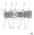
- the only figure shows a valve, which with consumers a drive as well as a pump and a filter unit communicates.
- a temperature dependent Element 1 integrated in a slide 2 that due to falling temperature on temperature dependent Element 1 is the volume of the temperature-dependent element 1 reduced and thus the slide 2 with the help of a Spring force of the spring 3 is shifted so that a connection to the pump 6 with a connection to the consumers 5 is connected and hydraulic fluid directly from the pump can flow to consumers.
- the surface 8 with Hydraulic fluid via the connection to the pump 7 with the Pressure of the pump and the surface 9 via the connection to Pump 4 is pressurized by the pump, rise these pressure-dependent forces on each other, so that the Slider 2 is free from these hydraulic forces.
- the current temperature receives the hydraulic fluid from the pump can be provided be that from the connection to the pump 7 hydraulic fluid Via a throttle point directly into the pressure medium reservoir flows back and thus a permanent exchange the hydraulic fluid on the temperature-dependent element 1 takes place.
- the valve unit consists of a good temperature-conducting Material and is arranged in the drive that the housing of the valve unit the current pressure medium temperature records, it is ensured that the temperature-dependent Element 1 always with the current pressure medium temperature is flowing around.
Landscapes
- Engineering & Computer Science (AREA)
- Chemical & Material Sciences (AREA)
- Analytical Chemistry (AREA)
- Physics & Mathematics (AREA)
- Fluid Mechanics (AREA)
- Mechanical Engineering (AREA)
- General Engineering & Computer Science (AREA)
- Fluid-Pressure Circuits (AREA)
- Details Of Reciprocating Pumps (AREA)
Abstract
Description
- 1
- temperaturabhängiges Element
- 2
- Schieber
- 3
- Feder
- 4
- Verbindung zur Pumpe
- 5
- Verbindung zu den Verbrauchern
- 6
- Verbindung zur Pumpe
- 7
- Verbindung zur Pumpe
- 8
- Fläche
- 9
- Fläche
Claims (7)
- Hydraulisches System zur Filterung von Druckflüssigkeit, bei welchem Druckflüssigkeit von einer Pumpe über eine Filtereinheit zu Verbrauchern gefördert wird, dadurch gekennzeichnet, daß, unabhängig von einem Druckniveau vor der Filtereinheit, unterhalb eines zuvor definierten Temperaturniveaus ein Teil der Druckflüssigkeit von der Pumpe direkt zu den Verbrauchern gefördert wird und oberhalb eines bestimmten Druckniveaus die geförderte Druckflüssigkeit über die Filtereinheit zu den Verbrauchern gefördert wird.
- Hydraulisches System zur Filterung von Druckflüssigkeit nach Anspruch 1, dadurch gekennzeichnet, daß in einem Ventil, welches zwischen der Filtereinheit und der Pumpe angeordnet ist, über ein Element (1), dessen Volumen sich in Abhängigkeit der Temperatur ändert, ein Schieber (2) betätigt wird, über welchen entweder eine Pumpe mit einer Filtereinheit oder eine Pumpe mit Verbrauchern verbindbar ist.
- Hydraulisches System zur Filterung von Druckflüssigkeit nach Anspruch 2, dadurch gekennzeichnet, daß ein Element (1), welches sein Volumen in Abhängigkeit der Temperatur ändert, bei Erwärmung einen Schieber (2) gegen eine Federkraft verschiebt und bei sinkender Temperatur die Federkraft den Schieber (2) in Abhängigkeit der Volumenänderung des Elements (1) zurückschiebt.
- Hydraulisches System zur Filterung von Druckflüssigkeit nach Anspruch 2, dadurch gekennzeichnet, daß ein Element (1), welches bei Änderung der Temperatur sein Volumen oder seine Form ändert, mit der Druckflüssigkeit vor der Filtereinheit in Verbindung steht.
- Hydraulisches System zur Filterung von Druckflüssigkeit nach Anspruch 2, dadurch gekennzeichnet, daß die hydraulischen Kräfte, welche auf den Schieber (2) wirken, sich gegenseitig in ihrer Wirkung auf den Schieber (2) aufheben.
- Hydraulisches System zur Filterung von Druckflüssigkeit nach Anspruch 1, dadurch gekennzeichnet, daß ein Filterelement von einem temperaturabhängigen Element (1) so bewegt werden kann, daß unterhalb einer zuvor definierten Temperatur Druckflüssigkeit von der Pumpe direkt zu den Verbrauchern gefördert wird und oberhalb einer zuvor definierten Temperatur das Filterelement diesen Durchlaß verschließt und Druckflüssigkeit von der Pumpe durch das Filterelement gefördert wird.
- Hydraulisches System zur Filterung von Druckflüssigkeit nach Anspruch 1, dadurch gekennzeichnet, daß Druckflüssigkeit in einem hydrostatischmechanischen Leistungsverzweigungsgetriebe gefiltert wird.
Applications Claiming Priority (2)
| Application Number | Priority Date | Filing Date | Title |
|---|---|---|---|
| DE19932097 | 1999-07-09 | ||
| DE19932097A DE19932097A1 (de) | 1999-07-09 | 1999-07-09 | Hydraulisches System zur Filterung von Druckflüssigkeit |
Publications (2)
| Publication Number | Publication Date |
|---|---|
| EP1067294A2 true EP1067294A2 (de) | 2001-01-10 |
| EP1067294A3 EP1067294A3 (de) | 2003-06-04 |
Family
ID=7914246
Family Applications (1)
| Application Number | Title | Priority Date | Filing Date |
|---|---|---|---|
| EP00113963A Withdrawn EP1067294A3 (de) | 1999-07-09 | 2000-07-01 | Filterumleitung eines hydraulischen Systems |
Country Status (2)
| Country | Link |
|---|---|
| EP (1) | EP1067294A3 (de) |
| DE (1) | DE19932097A1 (de) |
Citations (1)
| Publication number | Priority date | Publication date | Assignee | Title |
|---|---|---|---|---|
| DE19539759A1 (de) | 1995-10-26 | 1997-04-30 | Zahnradfabrik Friedrichshafen | Ölbehälter, insbesondere für hydraulische Lenksysteme von Kraftfahrzeugen |
Family Cites Families (7)
| Publication number | Priority date | Publication date | Assignee | Title |
|---|---|---|---|---|
| US2672984A (en) * | 1952-04-16 | 1954-03-23 | Luber Finer Inc | Filter |
| US2965120A (en) * | 1956-10-29 | 1960-12-20 | Gen Motors Corp | Pressure control device |
| US4036433A (en) * | 1975-11-06 | 1977-07-19 | Robertshaw Controls Company | Thermally operated control device and method of making the same |
| US4344564A (en) * | 1981-02-23 | 1982-08-17 | Gould Inc. | Thermal by-pass valve with integral pressure relief |
| DE4021292A1 (de) * | 1989-07-17 | 1991-01-31 | Volkswagen Ag | Filter |
| US5516042A (en) * | 1994-11-18 | 1996-05-14 | Dana Corporation | Thermally activated two-way valve |
| DE29705018U1 (de) * | 1996-06-26 | 1997-05-15 | Hydac Technology Gmbh, 66280 Sulzbach | Thermo-Bypass-Ventil |
-
1999
- 1999-07-09 DE DE19932097A patent/DE19932097A1/de not_active Withdrawn
-
2000
- 2000-07-01 EP EP00113963A patent/EP1067294A3/de not_active Withdrawn
Patent Citations (1)
| Publication number | Priority date | Publication date | Assignee | Title |
|---|---|---|---|---|
| DE19539759A1 (de) | 1995-10-26 | 1997-04-30 | Zahnradfabrik Friedrichshafen | Ölbehälter, insbesondere für hydraulische Lenksysteme von Kraftfahrzeugen |
Also Published As
| Publication number | Publication date |
|---|---|
| DE19932097A1 (de) | 2001-01-11 |
| EP1067294A3 (de) | 2003-06-04 |
Similar Documents
| Publication | Publication Date | Title |
|---|---|---|
| DE102007018504B4 (de) | Kühl- und Schmiermittelversorgungssystem eines Getriebes | |
| DE69113195T2 (de) | Fluidpumpe für Doppelfördermenge. | |
| EP0337124B1 (de) | Hydrostatisches Getriebe | |
| DE2354352A1 (de) | Pumpe | |
| DE2640898A1 (de) | Drehzahlwaechter | |
| DE4108915C2 (de) | Hydraulische Einrichtung zur Druckmittelversorgung eines bevorrechtigten Primärlastkreises | |
| WO2017125108A1 (de) | Hydraulische schaltanordnung für ein kraftfahrzeug | |
| DE4224973C2 (de) | Fluidversorgungssystem mit Druckbegrenzung | |
| WO2009103412A1 (de) | Hydrostatisches antriebssystem | |
| DE19542228B4 (de) | Vorrichtung zur Betätigung eines Hydraulik-Motors | |
| EP0446244B1 (de) | Steuereinrichtung für eine reibschlüssige überbrückungskupplung eines hydrodynamischen drehmomentwandlers | |
| DE2546600A1 (de) | Steuereinrichtung fuer eine hydraulikanlage | |
| DE102007039302A1 (de) | Hydraulisches System | |
| DE2024675A1 (de) | Einrichtung zur Filtrierung eines offenen Druckmittelkreises | |
| EP1220975B1 (de) | Fluidkühlvorrichtung | |
| DE102008000679A1 (de) | Hydraulische Steuerungsanordnung zum Steuern eines variablen Fluidvolumenstroms | |
| DE10104101A1 (de) | Drucksteuerventil | |
| DE2910623A1 (de) | Hydraulisches system | |
| DE102004017502B4 (de) | Drucksteuervorrichtung für einen Drehmomentübertragungsmechanismus | |
| DE69721622T2 (de) | Druckmittelsteuerkreis | |
| EP0955474A2 (de) | Druckölsystem mit Ölfilter und damit ausgestattetes Getriebe | |
| EP1067295A2 (de) | Filterumleitung eines hydraulischen Systems | |
| DE3107915C2 (de) | Hydraulische Steuereinrichtung, insbesondere Lenkeinrichtung | |
| WO2024115255A1 (de) | Vorrichtung für ein hydraulisches system, hydraulisches system, antriebsmodul eines kraftfahrzeugs | |
| DE19932097A1 (de) | Hydraulisches System zur Filterung von Druckflüssigkeit |
Legal Events
| Date | Code | Title | Description |
|---|---|---|---|
| PUAI | Public reference made under article 153(3) epc to a published international application that has entered the european phase |
Free format text: ORIGINAL CODE: 0009012 |
|
| AK | Designated contracting states |
Kind code of ref document: A2 Designated state(s): AT BE CH CY DE DK ES FI FR GB GR IE IT LI LU MC NL PT SE |
|
| AX | Request for extension of the european patent |
Free format text: AL;LT;LV;MK;RO;SI |
|
| PUAL | Search report despatched |
Free format text: ORIGINAL CODE: 0009013 |
|
| AK | Designated contracting states |
Designated state(s): AT BE CH CY DE DK ES FI FR GB GR IE IT LI LU MC NL PT SE |
|
| AX | Request for extension of the european patent |
Extension state: AL LT LV MK RO SI |
|
| 17P | Request for examination filed |
Effective date: 20030502 |
|
| 17Q | First examination report despatched |
Effective date: 20030903 |
|
| AKX | Designation fees paid |
Designated state(s): AT DE FR GB IT |
|
| STAA | Information on the status of an ep patent application or granted ep patent |
Free format text: STATUS: THE APPLICATION IS DEEMED TO BE WITHDRAWN |
|
| 18D | Application deemed to be withdrawn |
Effective date: 20040622 |