EP1066987A2 - Fahrzeugluftreifen - Google Patents
Fahrzeugluftreifen Download PDFInfo
- Publication number
- EP1066987A2 EP1066987A2 EP00114351A EP00114351A EP1066987A2 EP 1066987 A2 EP1066987 A2 EP 1066987A2 EP 00114351 A EP00114351 A EP 00114351A EP 00114351 A EP00114351 A EP 00114351A EP 1066987 A2 EP1066987 A2 EP 1066987A2
- Authority
- EP
- European Patent Office
- Prior art keywords
- carcass
- tire
- radius
- rim
- unloaded
- Prior art date
- Legal status (The legal status is an assumption and is not a legal conclusion. Google has not performed a legal analysis and makes no representation as to the accuracy of the status listed.)
- Granted
Links
Images


Classifications
-
- B—PERFORMING OPERATIONS; TRANSPORTING
- B60—VEHICLES IN GENERAL
- B60C—VEHICLE TYRES; TYRE INFLATION; TYRE CHANGING; CONNECTING VALVES TO INFLATABLE ELASTIC BODIES IN GENERAL; DEVICES OR ARRANGEMENTS RELATED TO TYRES
- B60C3/00—Tyres characterised by the transverse section
- B60C3/04—Tyres characterised by the transverse section characterised by the relative dimensions of the section, e.g. low profile
-
- B—PERFORMING OPERATIONS; TRANSPORTING
- B60—VEHICLES IN GENERAL
- B60C—VEHICLE TYRES; TYRE INFLATION; TYRE CHANGING; CONNECTING VALVES TO INFLATABLE ELASTIC BODIES IN GENERAL; DEVICES OR ARRANGEMENTS RELATED TO TYRES
- B60C9/00—Reinforcements or ply arrangement of pneumatic tyres
- B60C9/02—Carcasses
- B60C9/0292—Carcass ply curvature
Definitions
- the subject invention relates to a pneumatic vehicle tire with a profiled tread, especially a multi-layer Belt bandage, bead areas with bead cores and with one or more layers executed carcass with at least substantially radially extending Strengtheners, the carcass around the bead cores and each as Hochschlag runs back into the side walls, and being in the unloaded and depressurized condition of the tire and if it is mounted on a rim Interpretation of the course of the carcass deviates from the equilibrium figure.
- Such a tire is known for example from GB-A 2 024 738.
- Around to avoid undesirable deformations and tensions on the belt edges is suggested here in a certain way about the execution of the belt layers Influence on the carcass course in the depressurized or almost depressurized state to take pressure under the carcass course.
- British Patent 1,576,409 is concerned with the load-bearing capacity of a Pneumatic vehicle tire without sacrificing comfort or without an undesirable Tire warming must be accepted.
- the side walls or the carcass with a comparatively low curvature and to prevent them from being pressed under returns to a more bulbous shape.
- the belt bandage by the provision of special belt positions against bending moments in Circumferential direction designed very resistant.
- the contour the carcass in the tire which is usually at least approximately the same Sidewall contour corresponds, for a given internal pressure depending on the Determine or calculate the carcass length in the side walls.
- the heating mold for the tire is designed so that there is none if possible Changes in the contour of the carcass or the contour of the tire sidewalls, starting from the contour determined by the heating form up to the contour that the tire takes on under pressure when installed.
- the carcass according to its neutral is designed. This is supposed to cause unnecessary tension in the tire due to any Changes in shape can be avoided.
- tires In the tread area have tires furthermore usually a contour curved in the transverse direction, so that during compression under internal pressure and load within the driving surface, the area contacting the ground, the tire, effective contact pressure are balanced, what for power transmission and building the desired Load capacity is required.
- This curvature like the curvature of the Carcass in the side wall areas, determined by the shape of the tire, but it is on the finished product also on the constructive structure of the strengthening Elements, reinforcements in the belt and in the carcass, depending.
- a number of patent-pending or patent-protected ideas deals with an optimal design of the outer contour of Pneumatic vehicle tires, for example EP-A1 0 269 301, and also with measures, through which the pressure of the tire in the ground contact area and / or the contour the ground contact area itself should be influenced, especially around the Reduce rolling resistance or achieve more even wear.
- EP-B1 0 323 519 The Known measures usually take an interpretation of the curvature of the Tire in the tread area.
- the invention has now set itself the task of achieving the desired balanced Contact pressure conditions within the part of the tire in contact with the ground, the driving surface, through measures taken to design the carcass, in particular the braking behavior on wet and dry roads, the To positively influence noise development and abrasion behavior.
- the object is achieved according to the invention in that the carcass each in the area between their connection point to the belt and their Connection point to the rim is made in a length that is shorter than that the theoretical length of the carcass between these points according to the Equilibrium figure.
- the measure taken according to the present invention has an effect extremely favorable to the desired balanced pressure conditions in the ground contact area of the tire.
- the shorter carcass decreases in the Shoulder areas the extent of transmission by the tire pressure acting forces and thus causes an equalization of the pressure conditions in the footprint.
- Under inner pressure the tire sidewalls become like this deformed that the tire is wider compared to the depressurized state and in Zenith area grows somewhat and so against growth in the Belt edge areas acts, in particular even a reduction in the distance the belt edges to the bead.
- the design is made so that the length of the carcass between the two connecting parts 80 to 97%, in particular 85 to 95%, the theoretical determined in these areas according to the equilibrium figure Length corresponds. One can be located within these areas as far as possible achieve a balanced pressure distribution in the tire footprint.
- the average radius of the carcass is larger than the mean radius of one designed according to the equilibrium figure Carcass. This corresponds to a "straighter" interpretation of the carcass course.
- Tires designed according to the invention are preferably designed at the same time that the changing tensile and Compressive stresses in the carcass blows can be avoided.
- the carcass in the area between the Connection parts to the belt and the point with the largest cross-sectional width has a radius or a plurality of radii, all of which are smaller than that Radius or the radii in those areas of the carcass, each between the Steep with the largest cross-sectional width and the connecting parts to the rim run.
- FIGS. 2 and 3 and 4 each show schematic representations of Cross sections through halves of pneumatic vehicle tires
- FIG. 1 and FIG. 3 show the tire mounted on a rim in a depressurized and unloaded condition
- Fig. 2 and Fig. 4 the unloaded tire mounted on a fig under internal pressure (Nominal pressure according to E.T.R.T.O standards)
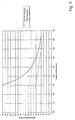
- Fig. 5 is a diagram showing the Course of the carcass radius over the side wall height for one according to the state of the Technology and for tires designed according to the invention.
- the pneumatic vehicle tires shown in cross section in FIGS. 1 to 4 are for Passenger cars provided radial radial tires.
- the invention is not limited to this type of tire and equally with Commercial vehicle tires realizable.
- the tire shown in FIGS. 1 to 4 is on a rim 10, of which only the bead seat 10a and the rim flange 10b are shown, arranged and has a profiled tread 1, a belt assembly 2, side walls 3, Bead areas 4 with bead cores 5 and a radial carcass 6.
- the Belt dressing 2 can and will be constructed in a conventional manner therefore in particular several belt layers with a crossing arrangement of Skill bearers and possibly a belt bandage as the radially outermost Include layer with skill carriers running in the tire circumferential direction.
- the carcass 6 is also single-ply executed and consists of embedded in a rubber or rubber matrix and at least substantially in the radial direction Strength members, preferably made of a textile material.
- the carcass 6 can therefore be constructed in a conventional manner and of course also include more than one layer.
- the carcass 6 is from led around inside out around the bead cores 5 and back into the Sidewall areas returned.
- the two recirculated areas of the carcass 6 each form the carcass flap 6a.
- the length of those areas is now the Carcass 6, which run in the side walls, specially designed or selected.
- the contour of the carcass into the Tire sidewalls is customary to insert the contour of the carcass into the Tire sidewalls to be designed so that they follow their neutral and therefore is designed according to the equilibrium formula.
- the Carcass or tire sidewall contour is also the form of heating for the tire in the Area of the side wall shells of their shape or contour designed so that if possible, no change in the carcass contour in the side walls and thus the tire sidewall contour starting from the contour in the heating mold up to Contour of the tire occurs under internal pressure. This is supposed to create unnecessary tension in the tire, which could occur due to changes in the shape of the tire become.
- a carcass 6 designed according to the invention is shorter in the side walls 3 executed as its length according to the neutral interpretation according to the Equilibrium formula or equilibrium figure would correspond and is from the Provide the heating mold of the tire with a much straighter course.
- the latter is from FIG. 1, where the tire is depressurized, evident.
- the shortened length of the carcass 6 compared to the equilibrium figure is set between two positions A and B.
- A is quasi the Connection point of the carcass 6 to the belt 2.
- the cross section of the tire results in A as the intersection of one drawn from the belt edge to the center of the tire Straight with the carcass 6.
- B is the connection point of the carcass 6 to the rim 10 and results from the intersection of a parallel to and through the tire axis the radially outermost point of contact of the bead area with the rim 10 straight lines with the carcass 6.
- the length of the carcass 6 is between the connection points A and B. 80% and 97%, especially between 85 and 95%, are calculated Resulting, corresponding length of the carcass 6 in these areas the equilibrium figure (equilibrium formula) chosen.
- the carcass 6 is in the unpressurized, unloaded and assembled state of the tire in cross section with a relatively large radius, wherein in in any case, the average radius of the carcass 6 is greater than the average radius a carcass designed according to the equilibrium figure.
- the course of the Carcass 6 designed so that when the tire is depressurized and when this is mounted on a rim, the carcass 6 in the lower side wall area flatter, therefore with a larger radius than in the upper one Side wall area in order to be targeted by the deformation under internal pressure Preload with outward tensile stresses in the high impact 6a To produce carcass 6. This ensures that the carcass is raised 6a 6 when changing from the sprung to the unsprung state during rolling of the tire essentially only fluctuating Is subjected to tensile stresses.
- Fig. 3 and Fig. 4 show a possible embodiment of the relevant interpretation of the course of the carcass 6, in which in the depressurized state (Fig. 3) between one of the two connection points A, B, which are defined as above, and the point B. max , which is the point with the largest cross-sectional width, essentially a radius R 1 , R 2 is selected.
- the radius R 1 is at least over the largest part of the length of the carcass 6 between A and B max and the radius R 2 is at least over the largest part of the length of the carcass 6 between B max and B.
- R 1 ⁇ R 2 in particular the ratio of the radii R 1 to R 2 is between 1: 1.1 and 1: 2.2, in particular between 1: 1.4 and 1: 2.0.
- An optimal design provides that in the depressurized state at the bead in Area B the largest radius of the carcass 6, in the area of A at the belt edge is the smallest and between points A and B the Radius of the carcass 6, and in the usual arrangement also that of the side wall 3, continuously enlarged.
- Fig. 5 shows the course of the carcass radius over the side wall height, wherein along the x-axis the tire height in millimeters and along the y-axis of the Radius of the carcass 6, also in millimeters.
- the dotted, in Essentially straight line shows the situation with one after the State of the art tires, where the course of the carcass according to the Neutral, according to the equilibrium formula.
- the solid line shows the course of a short, as explained above designed carcass.
- the dashed line shows the situation at one Carcass that is both short and with the radius starting from point A to point B continuously increases.
- Tread curvature When designing the contour of the carcass 6 according to the invention, it is advantageous if there are no further measures to influence the tire shape Tread curvature can be taken to have undesirable effects certain tire properties, such as abrasion and rolling resistance avoid. In the context of the present invention, it is advantageous if the Tread curvature is chosen to be comparatively flat and a corresponding one Curvature is made with one or two radii.
Landscapes
- Engineering & Computer Science (AREA)
- Mechanical Engineering (AREA)
- Tires In General (AREA)
Abstract
Description
Claims (6)
- Fahrzeugluftreifen mit einem profilierten Laufstreifen, einem insbesondere mehrere Lagen umfassenden Gürtelverband, Wulstbereichen mit Wulstkernen und mit einer ein- oder mehrlagig ausgeführten Karkasse mit zumindest im Wesentlichen radial verlaufenden Festigkeitsträgern, wobei die Karkasse um die Wulstkerne und jeweils als Hochschlag zurück in die Seitenwände verläuft und wobei im unbelasteten und drucklosen Zustand des Reifens sowie wenn dieser auf einer Felge montiert ist die Auslegung des Verlaufes der Karkasse von der Gleichgewichtsfigur abweicht, dadurch gekennzeichnet, dass die Karkasse (6) jeweils im Bereich zwischen ihrer Anbindungsstelle (A) zum Gürtel (2) und ihrer Anbindungsstelle (B) zur Felge (10) in einer Länge ausgeführt ist, die kürzer ist als die sich zwischen diesen Stellen (A, B) ergebende theoretische Länge der Karkasse (6) gemäß der Gleichgewichtsfigur.
- Fahrzeugluftreifen nach Anspruch 1, dadurch gekennzeichnet, dass die Länge der Karkasse (6) zwischen den beiden Anbindungsstellen (A, B) 80 bis 97 %, insbesondere 85 bis 95 %, der in diesen Bereichen gemäß der Gleichgewichtsfigur ermittelten theoretischen Länge entspricht.
- Fahrzeugluftreifen nach Anspruch 1 oder 2, dadurch gekennzeichnet, dass im drucklosen, unbelasteten und montierten Zustand des Reifens der mittlere Radius der Karkasse (6) größer ist als der mittlere Radius einer gemäß der Gleichgewichtsfigur ausgelegten Karkasse.
- Fahrzeugluftreifen nach Anspruch 1 oder 2, dadurch gekennzeichnet, dass im drucklosen, unbelasteten und auf einer Felge montierten Zustand des Reifens die Karkasse (6) im Bereich zwischen der Anbindungsstelle (A) zum Gürtel (2) und der Stelle (Bmax) mit der größten Querschnittsbreite einen Radius bzw. mehrere Radien aufweist, die sämtlich kleiner sind als der Radius bzw. die Radien in jenen Bereichen der Karkasse (6), die jeweils zwischen der Stelle (Bmax) mit der größten Querschnittsbreite und der Anbindungsstelle (B) zur Felge (10) verlaufen.
- Fahrzeugluftreifen nach Anspruch 4, dadurch gekennzeichnet, dass im drucklosen, unbelasteten und montierten Zustand des Reifens das Verhältnis des kleinsten Radius der Karkasse (6) zum größten Radius der Karkasse zwischen 1:1,1 und 1:2,2, insbesondere zwischen 1:1,4 und 1:2,0, beträgt.
- Fahrzeugluftreifen nach Anspruch 4 oder 5, dadurch gekennzeichnet, dass im drucklosen, unbelasteten und montierten Zustand des Reifens der Radius der Karkasse (6) im Bereich der Anbindungsstelle (A) zum Gürtel (2) am kleinsten, im Bereich der Anbindungstelle (B) zur Felge (10) am größten ist, und dass sich zwischen diesen beiden Stellen (A, B) der Radius der Karkasse (6) kontinuierlich vergrößert.
Applications Claiming Priority (2)
| Application Number | Priority Date | Filing Date | Title |
|---|---|---|---|
| DE19932027A DE19932027A1 (de) | 1999-07-09 | 1999-07-09 | Fahrzeugluftreifen |
| DE19932027 | 1999-07-09 |
Publications (3)
| Publication Number | Publication Date |
|---|---|
| EP1066987A2 true EP1066987A2 (de) | 2001-01-10 |
| EP1066987A3 EP1066987A3 (de) | 2002-01-02 |
| EP1066987B1 EP1066987B1 (de) | 2005-11-30 |
Family
ID=7914200
Family Applications (1)
| Application Number | Title | Priority Date | Filing Date |
|---|---|---|---|
| EP00114351A Expired - Lifetime EP1066987B1 (de) | 1999-07-09 | 2000-07-05 | Fahrzeugluftreifen |
Country Status (4)
| Country | Link |
|---|---|
| US (1) | US6640860B1 (de) |
| EP (1) | EP1066987B1 (de) |
| JP (1) | JP2001039111A (de) |
| DE (2) | DE19932027A1 (de) |
Families Citing this family (6)
| Publication number | Priority date | Publication date | Assignee | Title |
|---|---|---|---|---|
| JP4760722B2 (ja) * | 2006-09-25 | 2011-08-31 | 横浜ゴム株式会社 | 空気入りタイヤ |
| EP2423002B1 (de) | 2007-01-30 | 2016-09-21 | The Yokohama Rubber Co., Ltd. | Luftreifen |
| JP5366629B2 (ja) * | 2009-04-16 | 2013-12-11 | 株式会社ブリヂストン | 空気入りタイヤ |
| WO2012147356A1 (ja) * | 2011-04-26 | 2012-11-01 | 株式会社ブリヂストン | 空気入りタイヤ |
| JP7454391B2 (ja) * | 2020-01-29 | 2024-03-22 | Toyo Tire株式会社 | 空気入りタイヤ、空気入りタイヤの製造方法、及びタイヤ加硫金型 |
| JP7454390B2 (ja) * | 2020-01-29 | 2024-03-22 | Toyo Tire株式会社 | 空気入りラジアルタイヤ、空気入りラジアルタイヤの製造方法、及びタイヤ加硫金型 |
Family Cites Families (10)
| Publication number | Priority date | Publication date | Assignee | Title |
|---|---|---|---|---|
| GB1576409A (en) | 1976-02-17 | 1980-10-08 | Dunlop Ltd | Pneumatic tyres |
| FR2430858A1 (fr) | 1978-07-10 | 1980-02-08 | Michelin & Cie | Pneumatique a carcasse radiale |
| JPS59186702A (ja) * | 1983-03-30 | 1984-10-23 | Bridgestone Corp | 空気入りラジアルタイヤ |
| JPS62194904A (ja) * | 1986-02-20 | 1987-08-27 | Bridgestone Corp | 重荷重用空気入りラジアルタイヤ |
| DE3626123A1 (de) * | 1986-08-01 | 1988-02-11 | Heinz H Dr Ing Kotthaus | Luftbereiftes fahrzeugrad |
| EP0292563B1 (de) * | 1986-10-22 | 1991-07-24 | Sumitomo Rubber Industries Limited | Radialreifen für personenkraftwagen und verfahren zu dessen herstellung |
| JPH0764165B2 (ja) | 1986-11-10 | 1995-07-12 | 住友ゴム工業株式会社 | 乗用車用ラジアルタイヤ |
| EP0467490B1 (de) * | 1986-12-25 | 2001-01-17 | Bridgestone Corporation | Radialer Luftreifen für LKW |
| JP2885344B2 (ja) | 1987-07-08 | 1999-04-19 | 住友ゴム工業 株式会社 | 空気入りタイヤ |
| CA2018217C (en) * | 1989-06-06 | 1994-12-13 | Kiyoshi Ochiai | Radial tire |
-
1999
- 1999-07-09 DE DE19932027A patent/DE19932027A1/de not_active Ceased
-
2000
- 2000-07-05 EP EP00114351A patent/EP1066987B1/de not_active Expired - Lifetime
- 2000-07-05 DE DE50011733T patent/DE50011733D1/de not_active Expired - Lifetime
- 2000-07-05 JP JP2000203801A patent/JP2001039111A/ja not_active Withdrawn
- 2000-07-07 US US09/612,191 patent/US6640860B1/en not_active Expired - Lifetime
Also Published As
| Publication number | Publication date |
|---|---|
| DE50011733D1 (de) | 2006-01-05 |
| EP1066987A3 (de) | 2002-01-02 |
| US6640860B1 (en) | 2003-11-04 |
| JP2001039111A (ja) | 2001-02-13 |
| EP1066987B1 (de) | 2005-11-30 |
| DE19932027A1 (de) | 2001-01-18 |
Similar Documents
| Publication | Publication Date | Title |
|---|---|---|
| DE69708176T2 (de) | Notlaufring aus weichem Elastomermaterial für einen Reifen | |
| DE2600748C2 (de) | Reifen- Felgenanordnung | |
| DE69902793T2 (de) | Verstärkter radialreifenwulst | |
| DE2026874B2 (de) | Wulstkern fuer fahrzeugluftreifen | |
| DE4137529C2 (de) | Radial-Luftreifen | |
| EP2527163B1 (de) | Fahrzeugluftreifen | |
| DE60209012T2 (de) | Lufreifen mit asymmetrischen und verstärkten seitenwänden | |
| DE3752326T2 (de) | Radialer Luftreifen für LKW | |
| DE68918366T2 (de) | Radialer Luftreifen mit stärkeren Wulst-Gebieten. | |
| EP1066987B1 (de) | Fahrzeugluftreifen | |
| DE102006002455B4 (de) | Luftreifen | |
| EP0881105B1 (de) | Fahrzeugluftreifen | |
| DE69306166T2 (de) | Verbesserungen an Reifen-Verstärkungsstrukturen für Fahrzeugräder | |
| DE69914630T2 (de) | Reifen für fahrzeugräder mit verbesserter wulststruktur | |
| EP1284203B1 (de) | Fahrzeugluftreifen mit einer Gürtelbandage | |
| EP1092566B1 (de) | Fahrzeugluftreifen | |
| EP1361078B1 (de) | Pannenlauffähiger Fahrzeugluftreifen | |
| DE2152022B2 (de) | Fahrzeugluftreifen, bei dem die faeden der karkassenlagen in verschiedenen reifenbereichen zur umfangsrichtung unterschiedliche winkel bilden | |
| DE68910910T2 (de) | Luftreifen für hohe Geschwindigkeit. | |
| EP1066988B1 (de) | Fahrzeugluftreifen | |
| EP0683733A1 (de) | Fahrzeugrad. | |
| EP0847879A1 (de) | Gürtelreifen | |
| DE69011782T2 (de) | Radialer Luftreifen mit besserer Haltbarkeit der Wulste. | |
| EP2403724B1 (de) | Fahrzeugluftreifen | |
| EP1982849B1 (de) | Fahrzeugluftreifen mit Notlaufeigenschaften |
Legal Events
| Date | Code | Title | Description |
|---|---|---|---|
| PUAI | Public reference made under article 153(3) epc to a published international application that has entered the european phase |
Free format text: ORIGINAL CODE: 0009012 |
|
| AK | Designated contracting states |
Kind code of ref document: A2 Designated state(s): DE ES FR GB IT PT Kind code of ref document: A2 Designated state(s): AT BE CH CY DE DK ES FI FR GB GR IE IT LI LU MC NL PT SE |
|
| AX | Request for extension of the european patent |
Free format text: AL;LT;LV;MK;RO;SI |
|
| PUAL | Search report despatched |
Free format text: ORIGINAL CODE: 0009013 |
|
| AK | Designated contracting states |
Kind code of ref document: A3 Designated state(s): AT BE CH CY DE DK ES FI FR GB GR IE IT LI LU MC NL PT SE |
|
| AX | Request for extension of the european patent |
Free format text: AL;LT;LV;MK;RO;SI |
|
| 17P | Request for examination filed |
Effective date: 20020702 |
|
| AKX | Designation fees paid |
Free format text: DE ES FR GB IT PT |
|
| GRAP | Despatch of communication of intention to grant a patent |
Free format text: ORIGINAL CODE: EPIDOSNIGR1 |
|
| GRAS | Grant fee paid |
Free format text: ORIGINAL CODE: EPIDOSNIGR3 |
|
| GRAA | (expected) grant |
Free format text: ORIGINAL CODE: 0009210 |
|
| AK | Designated contracting states |
Kind code of ref document: B1 Designated state(s): DE ES FR GB IT PT |
|
| PG25 | Lapsed in a contracting state [announced via postgrant information from national office to epo] |
Ref country code: GB Free format text: LAPSE BECAUSE OF FAILURE TO SUBMIT A TRANSLATION OF THE DESCRIPTION OR TO PAY THE FEE WITHIN THE PRESCRIBED TIME-LIMIT Effective date: 20051130 Ref country code: IT Free format text: LAPSE BECAUSE OF FAILURE TO SUBMIT A TRANSLATION OF THE DESCRIPTION OR TO PAY THE FEE WITHIN THE PRESCRIBED TIME-LIMIT;WARNING: LAPSES OF ITALIAN PATENTS WITH EFFECTIVE DATE BEFORE 2007 MAY HAVE OCCURRED AT ANY TIME BEFORE 2007. THE CORRECT EFFECTIVE DATE MAY BE DIFFERENT FROM THE ONE RECORDED. Effective date: 20051130 |
|
| REG | Reference to a national code |
Ref country code: GB Ref legal event code: FG4D Free format text: NOT ENGLISH |
|
| REF | Corresponds to: |
Ref document number: 50011733 Country of ref document: DE Date of ref document: 20060105 Kind code of ref document: P |
|
| PG25 | Lapsed in a contracting state [announced via postgrant information from national office to epo] |
Ref country code: ES Free format text: LAPSE BECAUSE OF FAILURE TO SUBMIT A TRANSLATION OF THE DESCRIPTION OR TO PAY THE FEE WITHIN THE PRESCRIBED TIME-LIMIT Effective date: 20060313 |
|
| PG25 | Lapsed in a contracting state [announced via postgrant information from national office to epo] |
Ref country code: PT Free format text: LAPSE BECAUSE OF FAILURE TO SUBMIT A TRANSLATION OF THE DESCRIPTION OR TO PAY THE FEE WITHIN THE PRESCRIBED TIME-LIMIT Effective date: 20060502 |
|
| GBV | Gb: ep patent (uk) treated as always having been void in accordance with gb section 77(7)/1977 [no translation filed] |
Effective date: 20051130 |
|
| PLBE | No opposition filed within time limit |
Free format text: ORIGINAL CODE: 0009261 |
|
| STAA | Information on the status of an ep patent application or granted ep patent |
Free format text: STATUS: NO OPPOSITION FILED WITHIN TIME LIMIT |
|
| 26N | No opposition filed |
Effective date: 20060831 |
|
| EN | Fr: translation not filed | ||
| PG25 | Lapsed in a contracting state [announced via postgrant information from national office to epo] |
Ref country code: FR Free format text: LAPSE BECAUSE OF FAILURE TO SUBMIT A TRANSLATION OF THE DESCRIPTION OR TO PAY THE FEE WITHIN THE PRESCRIBED TIME-LIMIT Effective date: 20070119 |
|
| PG25 | Lapsed in a contracting state [announced via postgrant information from national office to epo] |
Ref country code: FR Free format text: LAPSE BECAUSE OF FAILURE TO SUBMIT A TRANSLATION OF THE DESCRIPTION OR TO PAY THE FEE WITHIN THE PRESCRIBED TIME-LIMIT Effective date: 20051130 |
|
| PGFP | Annual fee paid to national office [announced via postgrant information from national office to epo] |
Ref country code: DE Payment date: 20180731 Year of fee payment: 19 |
|
| REG | Reference to a national code |
Ref country code: DE Ref legal event code: R119 Ref document number: 50011733 Country of ref document: DE |
|
| PG25 | Lapsed in a contracting state [announced via postgrant information from national office to epo] |
Ref country code: DE Free format text: LAPSE BECAUSE OF NON-PAYMENT OF DUE FEES Effective date: 20200201 |