EP1065687A2 - Feuille avec contacts mobiles et interrupteur à feuilles - Google Patents
Feuille avec contacts mobiles et interrupteur à feuilles Download PDFInfo
- Publication number
- EP1065687A2 EP1065687A2 EP00113671A EP00113671A EP1065687A2 EP 1065687 A2 EP1065687 A2 EP 1065687A2 EP 00113671 A EP00113671 A EP 00113671A EP 00113671 A EP00113671 A EP 00113671A EP 1065687 A2 EP1065687 A2 EP 1065687A2
- Authority
- EP
- European Patent Office
- Prior art keywords
- sheet
- movable contacts
- holes
- receptacle holes
- receptacle
- Prior art date
- Legal status (The legal status is an assumption and is not a legal conclusion. Google has not performed a legal analysis and makes no representation as to the accuracy of the status listed.)
- Granted
Links
Images

Classifications
-
- H—ELECTRICITY
- H01—ELECTRIC ELEMENTS
- H01H—ELECTRIC SWITCHES; RELAYS; SELECTORS; EMERGENCY PROTECTIVE DEVICES
- H01H13/00—Switches having rectilinearly-movable operating part or parts adapted for pushing or pulling in one direction only, e.g. push-button switch
- H01H13/70—Switches having rectilinearly-movable operating part or parts adapted for pushing or pulling in one direction only, e.g. push-button switch having a plurality of operating members associated with different sets of contacts, e.g. keyboard
- H01H13/7006—Switches having rectilinearly-movable operating part or parts adapted for pushing or pulling in one direction only, e.g. push-button switch having a plurality of operating members associated with different sets of contacts, e.g. keyboard comprising a separate movable contact element for each switch site, all other elements being integrated in layers
-
- H—ELECTRICITY
- H01—ELECTRIC ELEMENTS
- H01H—ELECTRIC SWITCHES; RELAYS; SELECTORS; EMERGENCY PROTECTIVE DEVICES
- H01H13/00—Switches having rectilinearly-movable operating part or parts adapted for pushing or pulling in one direction only, e.g. push-button switch
- H01H13/50—Switches having rectilinearly-movable operating part or parts adapted for pushing or pulling in one direction only, e.g. push-button switch having a single operating member
- H01H13/52—Switches having rectilinearly-movable operating part or parts adapted for pushing or pulling in one direction only, e.g. push-button switch having a single operating member the contact returning to its original state immediately upon removal of operating force, e.g. bell-push switch
-
- H—ELECTRICITY
- H01—ELECTRIC ELEMENTS
- H01H—ELECTRIC SWITCHES; RELAYS; SELECTORS; EMERGENCY PROTECTIVE DEVICES
- H01H2205/00—Movable contacts
- H01H2205/016—Separate bridge contact
- H01H2205/024—Means to facilitate positioning
- H01H2205/026—Adhesive sheet
-
- H—ELECTRICITY
- H01—ELECTRIC ELEMENTS
- H01H—ELECTRIC SWITCHES; RELAYS; SELECTORS; EMERGENCY PROTECTIVE DEVICES
- H01H2213/00—Venting
- H01H2213/01—Venting with internal pressure of other switch sites
Definitions
- the present invention relates to a sheet with movable contacts and a sheet switch using the same, which are for use in operating panels of various electronic devices for example.
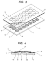
- FIG. 5 is a sectional view of the sheet with movable contacts
- Fig. 6 is a sectional view of a sheet switch using the sheet with movable contacts.
- the domed upper surfaces of the movable contacts 25 are covered with and fixed to the adhesive 23 which is applied to the lower surface of the sheet 21.
- the separator sheet 26 affixed to the lower surface of the sheet 21 is for preventing corrosion of the movable contacts 25 caused by gases contained in air or for preventing the adhesion of foreign matters to the movable contacts, during storage or transport of the sheet.
- the separator sheet 26 can be peeled off.
- the sheet exposed portions 21a free of the adhesive 23 are formed on the lower surface portions of the sheet 21 which surround the small holes 25a of the movable contacts 25, it is possible to prevent the entry of the adhesive 23 onto inner surfaces of the movable contacts from the small holes 25a.
- the sheet switch is made up of the above sheet with movable contacts and a circuit board 27 provided on an upper surface thereof with central fixed contacts 29 and outer fixed contacts 28.
- the movable contacts 25 are affixed onto the circuit board 27 using the adhesive 23 applied to the lower surface of the sheet 21 in such a manner that lower ends of the outer peripheries of the movable contacts 25 are respectively brought into abutment with the outer fixed contacts 28 and that central portions thereof are opposed to the central fixed contacts 29.
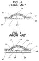
- the associated movable contact 25 is depressed by a depressing portion formed on a lower surface of the operating portion via the sheet 21 and is inverted, so that its central portion comes into abutment against the associated central fixed contact 29 on the circuit board, whereby the central fixed contact 29 and the associated outer fixed contact 28 on the circuit board 27 are electrically connected with each other.
- the central portion of the movable contact 25 is disconnected from the central fixed contact 29 with an elastic restoring force of the movable contact.
- the portions of the sheet 21 which surround the domed movable contacts 25 are fixed with the adhesive 23, so when any of the movable contacts 25 is depressed, the air present within the dome of the depressed movable contact cannot escape anywhere, thus giving rise to the problem that the operation feeling is deteriorated.
- a sheet with movable contacts comprising a first sheet formed by an insulating film, the first sheet having a plurality of receptacle holes and with adhesives applied respectively to both sides of the first sheet, a plurality of domed, metallic, movable contacts respectively received in the receptacle holes and having central small holes, and a second sheet formed by an insulating film and affixed onto the first sheet so as to cover upper surfaces of the plural movable contacts, wherein the first sheet has connecting slots formed therein for connecting adjacent such receptacle holes with each other, and each of the receptacle holes is larger than each of the small holes formed in the movable contacts and smaller than an external form of each of the movable contacts.
- a separator sheet whose upper surface has been subjected to a release treatment is affixed to the lower surface of the first sheet so as to be releasable from the first sheet.
- a sheet switch comprising a circuit board having a plurality of fixed contacts; a plurality of domed, metallic, movable contacts each having a small hole formed in a central portion thereof; a first sheet having a plurality of receptacle holes and connecting slots for connecting adjacent such receptacle holes with each other, the receptacle holes being each larger than the small hole formed in each of the movable contacts and smaller than an external form of each of the movable contacts; and a second sheet formed by an insulating film and affixed onto the first sheet, wherein the domed, metallic, movable contacts are received respectively in the receptacle holes of the first sheet so as to be opposed to the fixed contacts on the circuit board and in this state the first sheet is affixed onto the circuit board.
- FIGS. 1 and 2 show a structure of a sheet with movable contacts embodying the present invention, of which Fig. 1 is a partially cut-away perspective view of the sheet and Fig. 2 is a sectional view of a movable contact portion.
- a second sheet 4, like the first sheet 1, is also formed by a film of an insulating material such as a synthetic resin, e.g. PET (polyethylene terephthalate).
- an insulating material such as a synthetic resin, e.g. PET (polyethylene terephthalate).
- the movable contacts 5 are inserted through the plural receptacle holes 1a formed in the lower surface of the sheet 1 and the movable contacts are affixed, each at an outer peripheral end portion of the dome external form, to the adhesive lower surfaces of the first sheet 1 on the underside of the receptacle holes 1a to which lower surfaces the adhesive 3 is applied.
- the central portions of the movable contacts 5 are abutted against a lower surface of the second sheet 4 and the movable contacts are received respectively in the receptacle holes 1a of the first sheet 1.
- the upper surface of the separator sheet 6 is registered with and affixed to the adhesive lower surface of the first sheet 1 to which the adhesive 3 is applied, to complete the assembly.
- the adhesive surface of the first sheet 1 with the adhesive 3 applied thereto is not affixed to the central small holes 5a and the peripheral surfaces thereof in the movable contacts 5, so there is no fear of entry of the adhesive 3 to the inner surface side of the movable contacts through the small holes 5a, whereby it is possible to prevent the occurrence of an incomplete state of contact.
- Figs. 3 and 4 show a structure of a sheet switch using the sheet with movable contacts according to the present invention, of which Fig. 3 is a partially cut-away exploded perspective view of the sheet switch and Fig. 4 is a sectional view of a movable contact portion and a fixed contact portion.
- Figs. 1 and 2 the same components as in Figs. 1 and 2 are identified by the same reference numerals as in Figs. 1 and 2 and explanations thereof will here be omitted.
- a circuit board 7 is formed, for example, by an insulating laminate such as a phenolic resin laminate.
- a circuit board 7 On the circuit board 7 are formed a plurality of circuit patterns of outer fixed contacts 8 and central fixed contacts 9 by, for example, printing carbon or etching copper foil.
- the sheet switch is assembled in the following manner.
- the separator sheet 6 is peeled off from the sheet with movable contacts, for example, by pulling it with hands. Thereafter, the sheet with movable contacts is positioned onto the circuit board and the movable contacts, whose upper surfaces are affixed to the first sheet 1 and which are received in the receptacle holes 1a of the first sheet, are affixed onto the circuit board 7 through the adhesive lower surface of the second sheet 4 with the adhesive 5 applied thereto in such a manner that lower ends 5b of outer peripheries of the movable contacts 5 are abutted against the outer fixed contacts 8 and that the central small holes 5a of the movable contacts are opposed to the central fixed contacts 9.
- the assembly is now over.
- a plurality of circular receptacle holes 1a for receiving the movable contacts 5 therein are formed in the first sheet 1 and connecting slots 1b for connecting adjacent receptacle holes 1a with each other are formed in the receptacle holes 1a, so when any of the movable contacts 5 is depressed through the second sheet 4, air 10 present in the dome of the movable contact 5 which is dome-shaped is conducted to the next receptacle hole 1a through the connecting slot 1b located therebetween.
- each movable contact except the small hole portion is affixed to the adhesive lower surface of the first sheet and in this state the movable contact is received in the associated receptacle hole, there is no fear of entry of the adhesive to the inner surface side of the movable contact through the small hole and hence it is possible to prevent the occurrence of an incomplete state of contact.
- the first sheet having plural receptacle holes and with adhesives applied to both sides thereof there are formed connecting slots for connecting adjacent receptacle holes with each other, the receptacle holes being each larger than the small hole formed in each movable contact and smaller than the external form of each movable contact.
- the sheet with movable contacts thus constructed is affixed onto the circuit board with the adhesive applied to the lower surface of the first sheet. Accordingly, the air present in the dome of each domed movable contact can escape into the next receptacle hole through the associated connecting slot and hence the movable contact can surely be inverted within the associated receptacle hole, thus affording a good operation feeling. Additionally, also when any of the movable contacts located near the outer periphery of the sheet switch is depressed, it is possible to prevent floating of the sheet and hence possible to prevent the entry of dust, thereby ensuring a stable contact.
Landscapes
- Push-Button Switches (AREA)
Applications Claiming Priority (2)
| Application Number | Priority Date | Filing Date | Title |
|---|---|---|---|
| JP11183237A JP2001014974A (ja) | 1999-06-29 | 1999-06-29 | 可動接点付きシート及びシートスイッチ |
| JP18323799 | 1999-06-29 |
Publications (3)
| Publication Number | Publication Date |
|---|---|
| EP1065687A2 true EP1065687A2 (fr) | 2001-01-03 |
| EP1065687A3 EP1065687A3 (fr) | 2002-05-08 |
| EP1065687B1 EP1065687B1 (fr) | 2003-09-17 |
Family
ID=16132186
Family Applications (1)
| Application Number | Title | Priority Date | Filing Date |
|---|---|---|---|
| EP00113671A Expired - Lifetime EP1065687B1 (fr) | 1999-06-29 | 2000-06-28 | Feuille avec contacts mobiles et interrupteur à feuilles |
Country Status (7)
| Country | Link |
|---|---|
| US (1) | US6259046B1 (fr) |
| EP (1) | EP1065687B1 (fr) |
| JP (1) | JP2001014974A (fr) |
| KR (1) | KR100376339B1 (fr) |
| CN (1) | CN1137500C (fr) |
| DE (1) | DE60005254T2 (fr) |
| TW (1) | TW503413B (fr) |
Cited By (6)
| Publication number | Priority date | Publication date | Assignee | Title |
|---|---|---|---|---|
| EP1233435A1 (fr) * | 2001-02-16 | 2002-08-21 | Matsushita Electric Industrial Co., Ltd. | Unité de contact movible, interrupteur l'utilisant et procédé de fabrication |
| WO2002091415A1 (fr) * | 2001-05-03 | 2002-11-14 | 3M Innovative Properties Company | Batterie de touches etanche aux liquides |
| WO2003083531A1 (fr) * | 2002-03-27 | 2003-10-09 | 3M Innovative Properties Company | Films de fixation profiles de verrouillage utilises comme guides d'ondes a des fins d'eclairage |
| EP1406276A1 (fr) * | 2001-06-07 | 2004-04-07 | Fujikura Ltd. | Feuille metallique en forme de dome, procede de fabrication correspondant, et systeme metallique en forme de dome |
| DE10236436B4 (de) * | 2001-08-08 | 2005-12-08 | Yazaki Corp. | Schalter |
| EP1696449A2 (fr) * | 2005-02-25 | 2006-08-30 | Nokia Corporation | Structure pour un clavier |
Families Citing this family (40)
| Publication number | Priority date | Publication date | Assignee | Title |
|---|---|---|---|---|
| JP2002216580A (ja) * | 2001-01-18 | 2002-08-02 | Alps Electric Co Ltd | 接点板及び接点板付きシート及びこれを用いたスイッチ装置 |
| TW551554U (en) * | 2001-12-21 | 2003-09-01 | Lite On Technology Corp | Portable keyboard structure |
| KR100512374B1 (ko) * | 2003-01-27 | 2005-09-05 | 삼성전자주식회사 | 메탈돔 스위치의 키 패턴 연결장치 |
| US7161106B2 (en) * | 2003-11-06 | 2007-01-09 | Nike, Inc. | Switching device for flexible material |
| JP3808073B2 (ja) * | 2003-12-05 | 2006-08-09 | シチズン電子株式会社 | キーシートモジュール |
| TWI286333B (en) * | 2004-03-26 | 2007-09-01 | Hon Hai Prec Ind Co Ltd | A dome sheet and a switch using the same |
| JP4612361B2 (ja) * | 2004-08-31 | 2011-01-12 | ポリマテック株式会社 | キースイッチ |
| JP2006164870A (ja) * | 2004-12-10 | 2006-06-22 | Matsushita Electric Ind Co Ltd | 可動接点体およびそれを用いて構成したパネルスイッチ |
| JP2006294429A (ja) * | 2005-04-12 | 2006-10-26 | Matsushita Electric Ind Co Ltd | 可動接点体およびそれを用いて構成されたパネルスイッチ |
| US7253368B1 (en) * | 2006-03-27 | 2007-08-07 | Zippy Technology Corp. | Pin anchoring structure for button switches |
| JP2010027534A (ja) * | 2008-07-24 | 2010-02-04 | Panasonic Corp | 導光シート及びこれを用いた可動接点体 |
| US20100109921A1 (en) * | 2008-10-30 | 2010-05-06 | Sony Ericsson Mobile Communications Ab | Dome sheet and key pad |
| US20120206361A1 (en) * | 2011-02-11 | 2012-08-16 | Research In Motion Limited | Keypad having a metal grid for use with a portable electronic device |
| KR101153993B1 (ko) * | 2011-08-09 | 2012-06-11 | 주식회사 두성테크 | 테이프 시트 연배열 부착 방법 |
| JP5590745B2 (ja) * | 2012-08-22 | 2014-09-17 | 不二電子工業株式会社 | ロングストローク・ドーム型可動接片 |
| CN103681017A (zh) * | 2012-09-12 | 2014-03-26 | 不二电子工业株式会社 | 长冲程圆顶形可动触片 |
| US9502193B2 (en) | 2012-10-30 | 2016-11-22 | Apple Inc. | Low-travel key mechanisms using butterfly hinges |
| US9710069B2 (en) | 2012-10-30 | 2017-07-18 | Apple Inc. | Flexible printed circuit having flex tails upon which keyboard keycaps are coupled |
| EP2954384B1 (fr) | 2013-02-06 | 2023-08-02 | Apple Inc. | Dispositif d'entrée/sortie ayant une apparence et une fonction réglables dynamiquement |
| WO2014193850A1 (fr) | 2013-05-27 | 2014-12-04 | Apple Inc. | Ensemble interrupteur à course réduite |
| US9908310B2 (en) | 2013-07-10 | 2018-03-06 | Apple Inc. | Electronic device with a reduced friction surface |
| WO2015047661A1 (fr) | 2013-09-30 | 2015-04-02 | Apple Inc. | Touches de clavier d'épaisseur réduite |
| WO2015047606A1 (fr) | 2013-09-30 | 2015-04-02 | Apple Inc. | Dessus de touche à épaisseur réduite |
| WO2016025890A1 (fr) | 2014-08-15 | 2016-02-18 | Apple Inc. | Clavier équipé de tissu |
| US10082880B1 (en) | 2014-08-28 | 2018-09-25 | Apple Inc. | System level features of a keyboard |
| WO2016053898A1 (fr) | 2014-09-30 | 2016-04-07 | Apple Inc. | Ensemble électroluminescent pour clavier |
| CN205595253U (zh) | 2015-05-13 | 2016-09-21 | 苹果公司 | 电子装置、铰接结构和键机构 |
| WO2016183488A1 (fr) | 2015-05-13 | 2016-11-17 | Apple Inc. | Ensembles clavier ayant des épaisseurs réduites et procédé de formation d'ensembles clavier |
| US9997304B2 (en) | 2015-05-13 | 2018-06-12 | Apple Inc. | Uniform illumination of keys |
| JP6637070B2 (ja) | 2015-05-13 | 2020-01-29 | アップル インコーポレイテッドApple Inc. | 電子デバイス用のキーボード |
| US9934915B2 (en) | 2015-06-10 | 2018-04-03 | Apple Inc. | Reduced layer keyboard stack-up |
| US9971084B2 (en) | 2015-09-28 | 2018-05-15 | Apple Inc. | Illumination structure for uniform illumination of keys |
| US9803310B1 (en) * | 2016-07-12 | 2017-10-31 | Haier Us Appliance Solutions, Inc. | Appliance interface and input chassis |
| US10353485B1 (en) | 2016-07-27 | 2019-07-16 | Apple Inc. | Multifunction input device with an embedded capacitive sensing layer |
| US10115544B2 (en) | 2016-08-08 | 2018-10-30 | Apple Inc. | Singulated keyboard assemblies and methods for assembling a keyboard |
| US10755877B1 (en) | 2016-08-29 | 2020-08-25 | Apple Inc. | Keyboard for an electronic device |
| US11500538B2 (en) | 2016-09-13 | 2022-11-15 | Apple Inc. | Keyless keyboard with force sensing and haptic feedback |
| CN117270637A (zh) | 2017-07-26 | 2023-12-22 | 苹果公司 | 具有键盘的计算机 |
| CN108198721A (zh) * | 2018-01-23 | 2018-06-22 | 深圳市东强精密塑胶电子有限公司 | 一种新型的超薄轻触开关 |
| JP6975663B2 (ja) * | 2018-03-01 | 2021-12-01 | アルプスアルパイン株式会社 | スイッチモジュール |
Citations (3)
| Publication number | Priority date | Publication date | Assignee | Title |
|---|---|---|---|---|
| US4042439A (en) * | 1975-05-12 | 1977-08-16 | Kb-Denver, Inc. | Method of making keyboard assemblies |
| US4397082A (en) * | 1980-06-16 | 1983-08-09 | Sheldahl, Inc. | Membrane switch having adhesive label as edge seal |
| DE19746031A1 (de) * | 1996-10-22 | 1998-04-23 | Matsushita Electric Ind Co Ltd | Beweglicher Kontaktkörper eines Tastenfeldschalters und mit dem beweglichen Kontaktkörper ausgerüsteter Tastenfeldschalter |
Family Cites Families (7)
| Publication number | Priority date | Publication date | Assignee | Title |
|---|---|---|---|---|
| US4375018A (en) * | 1980-06-16 | 1983-02-22 | Sheldahl, Inc. | Membrane switch having adhesive label as edge seal |
| US4367385A (en) * | 1981-01-26 | 1983-01-04 | W. H. Brady Co. | Capacitance switch |
| US4684767A (en) * | 1985-05-30 | 1987-08-04 | Phalen Robert F | Tactile affirmative response membrane switch |
| US4771139A (en) * | 1986-06-27 | 1988-09-13 | Desmet Gregory L | Keyboard with metal cover and improved switches |
| JPH06131944A (ja) * | 1992-10-19 | 1994-05-13 | Fujitsu Ltd | メンブレンスイッチ |
| US5399823A (en) * | 1993-11-10 | 1995-03-21 | Minimed Inc. | Membrane dome switch with tactile feel regulator shim |
| US5845766A (en) | 1997-04-17 | 1998-12-08 | Matsushita Electric Industrial Co., Ltd. | Movable contact element for panel switch and method of manufacturing panel switch with movable contact element |
-
1999
- 1999-06-29 JP JP11183237A patent/JP2001014974A/ja not_active Withdrawn
-
2000
- 2000-05-29 TW TW089110398A patent/TW503413B/zh not_active IP Right Cessation
- 2000-06-23 CN CNB001078275A patent/CN1137500C/zh not_active Expired - Fee Related
- 2000-06-26 KR KR10-2000-0035365A patent/KR100376339B1/ko not_active IP Right Cessation
- 2000-06-27 US US09/604,353 patent/US6259046B1/en not_active Expired - Fee Related
- 2000-06-28 DE DE60005254T patent/DE60005254T2/de not_active Expired - Fee Related
- 2000-06-28 EP EP00113671A patent/EP1065687B1/fr not_active Expired - Lifetime
Patent Citations (3)
| Publication number | Priority date | Publication date | Assignee | Title |
|---|---|---|---|---|
| US4042439A (en) * | 1975-05-12 | 1977-08-16 | Kb-Denver, Inc. | Method of making keyboard assemblies |
| US4397082A (en) * | 1980-06-16 | 1983-08-09 | Sheldahl, Inc. | Membrane switch having adhesive label as edge seal |
| DE19746031A1 (de) * | 1996-10-22 | 1998-04-23 | Matsushita Electric Ind Co Ltd | Beweglicher Kontaktkörper eines Tastenfeldschalters und mit dem beweglichen Kontaktkörper ausgerüsteter Tastenfeldschalter |
Cited By (13)
| Publication number | Priority date | Publication date | Assignee | Title |
|---|---|---|---|---|
| EP1233435A1 (fr) * | 2001-02-16 | 2002-08-21 | Matsushita Electric Industrial Co., Ltd. | Unité de contact movible, interrupteur l'utilisant et procédé de fabrication |
| US6604278B2 (en) | 2001-02-16 | 2003-08-12 | Matsushita Electric Industrial Co., Ltd. | Manufacturing method for panel switch using movable contact unit and the movable contact unit |
| WO2002091415A1 (fr) * | 2001-05-03 | 2002-11-14 | 3M Innovative Properties Company | Batterie de touches etanche aux liquides |
| US7091952B2 (en) | 2001-05-03 | 2006-08-15 | 3M Innovative Properties Company | Liquid proof switch array |
| AU2002306528B2 (en) * | 2001-05-03 | 2006-06-15 | 3M Innovative Properties Company | Liquid proof switch array |
| EP1406276A4 (fr) * | 2001-06-07 | 2005-03-09 | Fujikura Ltd | Feuille metallique en forme de dome, procede de fabrication correspondant, et systeme metallique en forme de dome |
| US6917007B2 (en) | 2001-06-07 | 2005-07-12 | Fujikura, Ltd. | Metal dome sheet, its manufacturing method, and metal dome system |
| EP1406276A1 (fr) * | 2001-06-07 | 2004-04-07 | Fujikura Ltd. | Feuille metallique en forme de dome, procede de fabrication correspondant, et systeme metallique en forme de dome |
| DE10236436B4 (de) * | 2001-08-08 | 2005-12-08 | Yazaki Corp. | Schalter |
| US6827459B2 (en) | 2002-03-27 | 2004-12-07 | 3M Innovative Properties Company | Lighted fastening structure |
| WO2003083531A1 (fr) * | 2002-03-27 | 2003-10-09 | 3M Innovative Properties Company | Films de fixation profiles de verrouillage utilises comme guides d'ondes a des fins d'eclairage |
| EP1696449A2 (fr) * | 2005-02-25 | 2006-08-30 | Nokia Corporation | Structure pour un clavier |
| EP1696449A3 (fr) * | 2005-02-25 | 2008-03-12 | Nokia Corporation | Structure pour un clavier |
Also Published As
| Publication number | Publication date |
|---|---|
| DE60005254T2 (de) | 2004-07-01 |
| TW503413B (en) | 2002-09-21 |
| DE60005254D1 (de) | 2003-10-23 |
| CN1288244A (zh) | 2001-03-21 |
| EP1065687B1 (fr) | 2003-09-17 |
| KR100376339B1 (ko) | 2003-03-15 |
| KR20010021031A (ko) | 2001-03-15 |
| CN1137500C (zh) | 2004-02-04 |
| JP2001014974A (ja) | 2001-01-19 |
| US6259046B1 (en) | 2001-07-10 |
| EP1065687A3 (fr) | 2002-05-08 |
Similar Documents
| Publication | Publication Date | Title |
|---|---|---|
| US6259046B1 (en) | Sheet with movable contacts and sheet switch | |
| KR100456825B1 (ko) | 패널스위치용가동접점조립체 | |
| US6271491B1 (en) | Push button switch including dome-shaped movable contact having reverse function | |
| US6417467B1 (en) | Sheet with movable contacts and sheet switch | |
| US3973091A (en) | Pushbutton keyboard assembly having pole and inner contacts simultaneously engaged by a bridging contact | |
| US6512827B1 (en) | Portable terminal device | |
| KR20090007496A (ko) | 스위치 통합 케이싱 및 이 케이싱을 가진 전자기기 | |
| US6548779B2 (en) | Sheet having moving contacts and sheet switch | |
| KR20020061491A (ko) | 클릭감이 양호한 돔 형상 접점판 및 접점판이 장착된 시트 | |
| US7329823B2 (en) | Movable contact element and panel switch formed using the same | |
| US20100230267A1 (en) | Push switch | |
| KR100585298B1 (ko) | 누름버튼 스위치 | |
| US7075026B2 (en) | Movable contact body and panel switch using the same | |
| KR100515172B1 (ko) | 푸시버튼 스위치용 가동접점체 및 이를 사용한 스위치장치 | |
| JP4279129B2 (ja) | 可動接点付シート及びこれを用いた押釦スイッチ | |
| KR100384252B1 (ko) | 가동접점 및 이 가동접점을 사용한 스위치장치 | |
| GB1593414A (en) | Keyboard switch assemblies | |
| JP2872304B2 (ja) | キーボードスイッチ | |
| JPH05128938A (ja) | キースイツチの構造 | |
| JP2002260486A (ja) | 電子機器のキースイッチ構造 | |
| JP2007109674A (ja) | パネルスイッチ用可動接点体及びそれを用いたパネルスイッチ | |
| JPH0721875A (ja) | 押ボタンスイッチ | |
| JPH0927239A (ja) | スイッチ構造 |
Legal Events
| Date | Code | Title | Description |
|---|---|---|---|
| PUAI | Public reference made under article 153(3) epc to a published international application that has entered the european phase |
Free format text: ORIGINAL CODE: 0009012 |
|
| AK | Designated contracting states |
Kind code of ref document: A2 Designated state(s): AT BE CH CY DE DK ES FI FR GB GR IE IT LI LU MC NL PT SE |
|
| AX | Request for extension of the european patent |
Free format text: AL;LT;LV;MK;RO;SI |
|
| PUAL | Search report despatched |
Free format text: ORIGINAL CODE: 0009013 |
|
| AK | Designated contracting states |
Kind code of ref document: A3 Designated state(s): AT BE CH CY DE DK ES FI FR GB GR IE IT LI LU MC NL PT SE |
|
| AX | Request for extension of the european patent |
Free format text: AL;LT;LV;MK;RO;SI |
|
| 17P | Request for examination filed |
Effective date: 20020523 |
|
| 17Q | First examination report despatched |
Effective date: 20020910 |
|
| AKX | Designation fees paid |
Designated state(s): DE FI FR GB |
|
| GRAH | Despatch of communication of intention to grant a patent |
Free format text: ORIGINAL CODE: EPIDOS IGRA |
|
| GRAS | Grant fee paid |
Free format text: ORIGINAL CODE: EPIDOSNIGR3 |
|
| GRAA | (expected) grant |
Free format text: ORIGINAL CODE: 0009210 |
|
| AK | Designated contracting states |
Kind code of ref document: B1 Designated state(s): DE FI FR GB |
|
| REG | Reference to a national code |
Ref country code: GB Ref legal event code: FG4D |
|
| REF | Corresponds to: |
Ref document number: 60005254 Country of ref document: DE Date of ref document: 20031023 Kind code of ref document: P |
|
| REG | Reference to a national code |
Ref country code: IE Ref legal event code: FG4D |
|
| ET | Fr: translation filed | ||
| PLBE | No opposition filed within time limit |
Free format text: ORIGINAL CODE: 0009261 |
|
| STAA | Information on the status of an ep patent application or granted ep patent |
Free format text: STATUS: NO OPPOSITION FILED WITHIN TIME LIMIT |
|
| 26N | No opposition filed |
Effective date: 20040618 |
|
| REG | Reference to a national code |
Ref country code: IE Ref legal event code: MM4A |
|
| PGFP | Annual fee paid to national office [announced via postgrant information from national office to epo] |
Ref country code: FR Payment date: 20050621 Year of fee payment: 6 |
|
| PGFP | Annual fee paid to national office [announced via postgrant information from national office to epo] |
Ref country code: FI Payment date: 20050623 Year of fee payment: 6 |
|
| PGFP | Annual fee paid to national office [announced via postgrant information from national office to epo] |
Ref country code: DE Payment date: 20050822 Year of fee payment: 6 |
|
| PG25 | Lapsed in a contracting state [announced via postgrant information from national office to epo] |
Ref country code: FI Free format text: LAPSE BECAUSE OF NON-PAYMENT OF DUE FEES Effective date: 20060628 |
|
| PG25 | Lapsed in a contracting state [announced via postgrant information from national office to epo] |
Ref country code: DE Free format text: LAPSE BECAUSE OF NON-PAYMENT OF DUE FEES Effective date: 20070103 |
|
| REG | Reference to a national code |
Ref country code: FR Ref legal event code: ST Effective date: 20070228 |
|
| PGFP | Annual fee paid to national office [announced via postgrant information from national office to epo] |
Ref country code: GB Payment date: 20070618 Year of fee payment: 8 |
|
| PG25 | Lapsed in a contracting state [announced via postgrant information from national office to epo] |
Ref country code: FR Free format text: LAPSE BECAUSE OF NON-PAYMENT OF DUE FEES Effective date: 20060630 |
|
| GBPC | Gb: european patent ceased through non-payment of renewal fee |
Effective date: 20080628 |
|
| PG25 | Lapsed in a contracting state [announced via postgrant information from national office to epo] |
Ref country code: GB Free format text: LAPSE BECAUSE OF NON-PAYMENT OF DUE FEES Effective date: 20080628 |