EP1065395B1 - Controlled magnetic bearing device - Google Patents
Controlled magnetic bearing device Download PDFInfo
- Publication number
- EP1065395B1 EP1065395B1 EP00900852A EP00900852A EP1065395B1 EP 1065395 B1 EP1065395 B1 EP 1065395B1 EP 00900852 A EP00900852 A EP 00900852A EP 00900852 A EP00900852 A EP 00900852A EP 1065395 B1 EP1065395 B1 EP 1065395B1
- Authority
- EP
- European Patent Office
- Prior art keywords
- signal
- control unit
- control
- magnetic bearing
- rotor
- Prior art date
- Legal status (The legal status is an assumption and is not a legal conclusion. Google has not performed a legal analysis and makes no representation as to the accuracy of the status listed.)
- Expired - Lifetime
Links
- 238000006073 displacement reaction Methods 0.000 claims description 68
- 238000012546 transfer Methods 0.000 claims description 14
- 230000008859 change Effects 0.000 claims description 12
- 238000003860 storage Methods 0.000 claims description 6
- 230000001360 synchronised effect Effects 0.000 description 14
- 235000012431 wafers Nutrition 0.000 description 14
- 238000012360 testing method Methods 0.000 description 10
- 230000000694 effects Effects 0.000 description 8
- 230000004044 response Effects 0.000 description 7
- 230000001965 increasing effect Effects 0.000 description 6
- 238000005096 rolling process Methods 0.000 description 5
- 238000002474 experimental method Methods 0.000 description 4
- 230000003321 amplification Effects 0.000 description 2
- 238000013016 damping Methods 0.000 description 2
- 238000010586 diagram Methods 0.000 description 2
- 230000004907 flux Effects 0.000 description 2
- 238000005259 measurement Methods 0.000 description 2
- 238000000034 method Methods 0.000 description 2
- 238000003199 nucleic acid amplification method Methods 0.000 description 2
- 230000010363 phase shift Effects 0.000 description 2
- 239000004065 semiconductor Substances 0.000 description 2
- 238000004088 simulation Methods 0.000 description 2
- 238000012795 verification Methods 0.000 description 2
- 238000004804 winding Methods 0.000 description 2
- 230000009471 action Effects 0.000 description 1
- 238000010923 batch production Methods 0.000 description 1
- 239000003990 capacitor Substances 0.000 description 1
- 230000001419 dependent effect Effects 0.000 description 1
- 230000006866 deterioration Effects 0.000 description 1
- 230000002708 enhancing effect Effects 0.000 description 1
- 238000000605 extraction Methods 0.000 description 1
- 238000001914 filtration Methods 0.000 description 1
- 239000012530 fluid Substances 0.000 description 1
- 230000006698 induction Effects 0.000 description 1
- 238000004519 manufacturing process Methods 0.000 description 1
- 230000008569 process Effects 0.000 description 1
- 238000012545 processing Methods 0.000 description 1
- 230000000630 rising effect Effects 0.000 description 1
- 230000035945 sensitivity Effects 0.000 description 1
Images


Classifications
-
- F—MECHANICAL ENGINEERING; LIGHTING; HEATING; WEAPONS; BLASTING
- F16—ENGINEERING ELEMENTS AND UNITS; GENERAL MEASURES FOR PRODUCING AND MAINTAINING EFFECTIVE FUNCTIONING OF MACHINES OR INSTALLATIONS; THERMAL INSULATION IN GENERAL
- F16C—SHAFTS; FLEXIBLE SHAFTS; ELEMENTS OR CRANKSHAFT MECHANISMS; ROTARY BODIES OTHER THAN GEARING ELEMENTS; BEARINGS
- F16C32/00—Bearings not otherwise provided for
- F16C32/04—Bearings not otherwise provided for using magnetic or electric supporting means
- F16C32/0406—Magnetic bearings
- F16C32/044—Active magnetic bearings
- F16C32/0444—Details of devices to control the actuation of the electromagnets
- F16C32/0451—Details of controllers, i.e. the units determining the power to be supplied, e.g. comparing elements, feedback arrangements with P.I.D. control
Definitions
- the present invention relates to a controller for a magnetic bearing in an apparatus using the magnetic bearing as a means for supporting a rotor, and more particularly to a controlled magnetic bearing apparatus suitable for suppressing a vibration amplitude in accordance with a whirling movement of an unbalanced rotor.
- FIG. 1 shows a basic configuration of a conventionally typical known controlled magnetic bearing apparatus having a feedback control system.
- a part of a bearing apparatus for radially supporting a rotating shaft 1 has been extracted and is designed to control a vibration amplitude of the rotor 1 in an X-axis direction on an X-Y plane (transverse plane) perpendicular to the rotating shaft 1.
- the horizontal axis is taken in an X-axis direction, and the vertical axis in a Y-axis direction, about a center of the rotor 1.
- Displacement sensors 2a, 2b, and electromagnets 3a, 3b are disposed on the X-axis with interposing the rotor 1 therebetween.
- An electric current to be supplied to the electromagnets 3a, 3b is controlled based on sensor signals from the displacement sensors 2a, 2b.
- Electromagnets and displacement sensors are similarly disposed on the Y-axis with interposing the rotor 1 therebetween, and an electric current is controlled in the same manner.
- the displacement sensors 2a, 2b which are disposed on the X-axis with interposing the rotor 1 therebetween, and which detect radial displacements of the rotating shaft 1, are connected to a sensor amplifier 4.
- the displacement sensors 2a, 2b and the sensor amplifier 4 constitute a displacement sensor unit.
- An output signal from the sensor amplifier 4 is an electric signal (sensor signal) corresponding to a displacement of the rotor 1 in the X-axis direction.
- the sensor signal is inputted into a first control unit 5 for generating a compensation signal utilized for holding the rotor 1 at a desired levitating position.
- the first control unit 5 calculates first control signals based on the sensor signal and outputs the first control signals as control currents.
- the control signals (control currents) are amplified by power amplifiers 6a, 6b respectively connected to the electromagnets 3a, 3b, and then supplied to coils of the electromagnets 3a, 3b.
- an electromagnetic force is generated by the electric current supplied to each of the coils of the electromagnets 3a, 3b.
- the rotor 1 is magnetically attracted to the electromagnets 3a, 3b by the electromagnetic forces.
- the control currents are supplied to a pair of the electromagnets 3a, 3b disposed at an opposite position to each other on the X-axis, and hence the rotor 1 is servo controlled so as to be held in a levitated state at a central position or a target position by the attracting forces of the electromagnets 3a, 3b.
- eccentric rotation of the rotor i.e., whirling
- the degree of eccentricity of the rotor becomes large, then the whirling range of the rotor cannot be within a touchdown gap of the magnetic bearing. Consequently, the rotor cannot be supported in a non-contact levitated state, and this may damage the device.
- a stiffness of a magnetic bearing is smaller than that of a rolling bearing or a sliding bearing.
- a magnetic bearing it is difficult for a magnetic bearing to have a stiffness equivalent to that of a rolling bearing or a sliding bearing.
- a magnetic flux density of 1 tesla is generated in a space where areas of 1 square centimeter are opposed to each other, an obtained attracting force is about 40 newtons as Maxwell's stress equation shows.
- a controlled magnetic bearing since a magnetic flux density is generally about 0.5 tesla, an attracting force of only about 10 newtons is obtained.
- US-A-4 128 795 closest prior art which describes a device for damping the critical frequencies of a rotor suspended by a radial electromagnetic bearing which has means associated therewith for detecting the radial position of the rotor, comprising a servo-circuit for connection between the detecting means and windings of the electromagnetic bearing and including a circuit for controlling the current supply to the windings in response to signals from the detecting means to keep the rotor in a predetermined radial position.
- the servo-circuit is provided with means for the selective amplification of the phase advance gain of said circuit in a frequency equal to the speed of rotation of the rotor for damping said critical frequencies.
- EP-A-0 313 727 which describes an active type magnetic bearing system includes magnetic bearings for suspending a rotary body to permit it to rotate about its rotational axis.
- a control system supplies the magnetic bearings with signals to control the radial position of the rotary body, and comprises displacement detecting circuits for detecting any displacement of the radial position of the rotary body and a control circuit for producing a control signal which serves to suppress any unstable vibration of the rotary body.
- the present invention has been made in view of the above drawbacks. It is therefore an object of the present invention to provide a controlled magnetic bearing apparatus which generates a control signal based on a sensor signal from a displacement sensor for detecting a radial displacement of a rotor to suppress whirling of the rotor due to an external force synchronized with a rotational movement, and can hence support the rotor stably in a levitated state.
- a voltage signal proportional to a rotational speed which is obtained from an existing motor controller, is used either for turning on and off a signal switch before a control signal is inputted into a power amplifier, or for operation of a rotational speed component extraction filter.
- a controlled magnetic bearing apparatus for radially supporting a rotor, comprising a displacement sensor for detecting a radial displacement of the rotor, a first control unit for calculating a first control signal based on a sensor signal from the displacement sensor and outputting the first control signal, a power amplifier for supplying an electric current based on the first control signal, and an electromagnet for generating a magnetic force based on a signal from the power amplifier, the controlled magnetic bearing apparatus further comprising: a second control unit disposed in parallel with the first control unit for generating a second control signal changed in phase from the sensor signal inputted therein and outputting the second control signal; and a signal synthesizer for adding the second control signal outputted from the second control unit to the first control signal outputted from the first control unit to generate a control signal and outputting the control signal to the power amplifier.
- the phase change amount in the second control unit is preferably set at a value suitable for suppressing whirling of the rotor, based on external force/displacement transfer characteristics of a magnetic bearing.
- a control force in a direction opposite to an external force acting on the whirling is exerted based on the control characteristics of the magnetic bearing, whereby the whirling can be suppressed.
- the control force is produced by adjusting the sensor signal to a suitable amount of a phase on the basis of the control characteristics of the magnetic bearing.
- a phase change amount based on the external force/displacement transfer characteristics of the magnetic bearing is suitable for suppressing whirling of the rotor.
- a set value of a phase adjustor in the second control unit is determined with reference to transfer characteristics (gain, phase) of the sensor signal from the displacement sensor relative to the input signal of the power amplifier in the conventional servo control.
- the output signal from the second control unit is added to the output signal from the first control unit.
- the sum is inputted into the power amplifier unit to control an electric current of the electromagnet, whereby whirling of the rotor can be suppressed.
- the second control unit comprises: a filter for extracting a rotational frequency component from the sensor signal; a phase adjustor for adjusting a phase of an output signal from the filter; a signal generator including a comparator for comparing an output signal from the phase adjustor with a reference electric potential; and a gain adjustor for adjusting an amplitude of an output signal from the signal generator.
- the second control unit comprises: a variable frequency filter; and means for imparting a phase change amount corresponding to a rotational speed of a motor and suitable for suppressing whirling of the rotor.
- the means for imparting the phase change amount corresponding to the rotational speed of the motor and suitable for suppressing whirling of the rotor preferably comprises a storage for measuring data on external force/displacement transfer characteristics of the magnetic bearing, and storing the measured data in correspondence with a rotational speed, and a phase adjustor for reading from the storage and adjusting the phase.
- the phase change amount corresponding to the rotational speed of the motor may be set with use of an arithmetic circuit which approximates the external force/displacement transfer characteristics of the magnetic bearing.
- a controlled magnetic bearing apparatus further comprising: a signal switch for switching on and off a flow of a signal in the second control unit; and a third control unit for comparing the sensor signal with a reference signal, and turning the signal switch on or off based on results of comparison.
- a controlled magnetic bearing apparatus further comprising: a signal switch for switching on and off a flow of a signal in the second control unit; and a fourth control unit including a comparator for comparing an actual rotational speed signal with a reference signal, and a signal generator for generating a command signal for turning the signal switch on or off.
- a second rotational frequency component extractor is preferably provided at the downstream side of a signal generator including a comparator in the second control unit. According to this arrangement, the output signal from the second control unit can be converted into a low-order sine wave by filtering out a harmonic wave component from a rectangular wave. Thus, troubles such as noises due to harmonic waves can be prevented.
- the controlled magnetic bearing apparatus preferably comprises a fifth control unit for comparing the sensor output before the signal switch in the second control unit is turned on, with the sensor output at the time when the signal switch is turned on, and outputting a command value for changing a set value of a gain in the gain adjustor.
- FIGS. 2 through 29C Embodiments of the present invention will be described below with reference to FIGS. 2 through 29C .
- the same reference numerals denote the same or corresponding portions.
- FIG. 2 is a schematic view showing a basic configuration of a controlled magnetic bearing apparatus according to an embodiment of the present invention.
- a part of a bearing apparatus for radially supporting a rotating shaft 1 has been extracted and is designed to control a vibration amplitude of the rotor 1 in an X-axis direction of an X-Y plane (transverse plane) perpendicular to the rotating shaft 1.
- the horizontal axis is taken in an X-axis direction, and the vertical axis in a Y-axis direction, about a center of the rotor 1.
- Displacement sensors 2a, 2b, and electromagnets 3a, 3b are disposed on the X-axis with interposing the rotor 1 therebetween. Electric currents to be supplied to the electromagnets 3a, 3b are controlled based on sensor signals from the displacement sensors 2a, 2b. Electromagnets and displacement sensors are similarly disposed on the Y-axis with interposing the rotor 1 therebetween, and electric currents are controlled in the same manner.
- the displacement sensors 2a, 2b which are disposed on the X-axis with interposing the rotor 1 therebetween and detect radial displacements of the rotating shaft 1, are connected to a sensor amplifier 4.
- the displacement sensors 2a, 2b and the sensor amplifier 4 constitute a displacement sensor unit.
- An output signal from the sensor amplifier 4 is an electric signal (sensor signal) corresponding to a displacement of the rotor 1 in the X-axis direction.
- the sensor signal is inputted into a first control unit 5 and a second control unit 7 disposed in parallel with the first control unit 5.
- the first control unit 5 calculates a first control signal based on the sensor signal, and outputs the first control signal as a control current.
- the second control unit 7 generates a second control signal changed in phase from the sensor signal, and outputs the second control signal as a control current.
- the first and second control signals (control currents) are synthesized (added together) by a signal synthesizer 8.
- the synthesized control signal is amplified by power amplifiers 6a, 6b respectively connected to the electromagnets 3a, 3b, and then supplied to coils of the electromagnets 3a, 3b. In each of the electromagnets 3a, 3b, an electromagnetic force is generated by the electric current supplied to each of the coils of the electromagnets 3a, 3b.
- the rotor 1 is magnetically attracted to the electromagnets 3a, 3b by the electromagnetic forces.
- the control currents are supplied to a pair of the electromagnets 3a, 3b disposed at an opposite position to each other on the X-axis, and hence the rotor 1 is servo controlled so as to be held in a levitated state at a center position by the attracting forces of the electromagnets 3a, 3b.
- FIG. 3 is a block diagram showing a control system with modeling the sensor amplifier 4, the first control unit 5, the second control unit 7, the power amplifiers 6a, 6b, the electromagnets 3a, 3b, and a magnetic bearing in the control system shown in FIG. 2 .
- the magnetic bearing is represented as the simplest system by the illustrated functions (1/MS 2 , K) based on the mass M of the rotor and the stiffness Ku of the magnetic bearing. In these functions, S denotes Laplacian.
- FIG. 4 shows an example of a configuration of the second control unit 7.
- the second control unit 7 comprises a buffer amplifier 7a, a rotational frequency component extractor 7b, a phase (phase shift) adjustor 7c, a signal generator 7d including a comparator, and a gain adjustor 7e.
- a rotational frequency component is extracted from the sensor signal amplified in the buffer amplifier 7a by the rotational frequency component extractor 7b, which is a filter.
- the phase of the extracted signal is adjusted by the phase adjustor 7c.
- an output signal from the phase adjustor 7c is compared with a reference electric potential by the comparator to thus generate a signal oscillating in positive and negative directions with respect to 0 V.
- a signal adjusted in amplitude by the gain adjustor 7e is outputted into the signal synthesizer 8.
- the sensor signal is passed through the rotational frequency component extractor 7b to extract a signal component corresponding to a rotational speed of a motor. Further, an adjustment amount of an arbitrary phase (phase shift) is imparted to the signal component. The resulting signal is received by the signal generator 7d including the comparator. Thus, frequency and phase information of the signal corresponding to the rotational speed of the motor is transmitted downstream. However, amplitude information is blocked. Since such a signal processing is required, the signal generator 7d including the comparator is used.
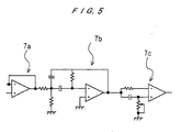
- FIG. 5 shows an example of a concrete circuit configuration of the buffer amplifier 7a, the rotational frequency component extractor 7b, and the phase adjustor 7c in the second control unit 7.
- these devices have a simple structure composed of general-purpose operational amplifiers and CR elements.
- the buffer amplifier 7a comprises an amplifier using an operational amplifier.
- the rotational frequency component extractor 7b comprises a filter circuit having a combination of an operational amplifier and CR elements.
- the phase adjustor 7c similarly comprises a circuit having a combination of an operational amplifier and CR elements, and can adjust a phase amount by adjusting a volume connected to the ground.
- a sine wave of the frequency component synchronized with the sensor signal from the displacement sensors 2a, 2b is extracted, and its phase is adjusted by adjusting the volume of the phase adjustor 7c.
- the phase adjustment within the range of 0 to 180 degrees can be achieved by adjusting the volume of the variable resistor.
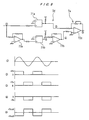
- FIG. 6 shows an example of a circuit configuration of the signal generator 7d including the comparator, and the gain adjustor 7e.
- FIG. 6 further shows signal waveforms in each of portions.
- the signal generator 7d comprises a circuit having a combination of comparators 71a, 71b and operational amplifiers 72a, 72b for inverting a sign.
- the signal generator 7d generates an output signal oscillating between the plus (+) side and minus (-) side with respect to 0 V (ground potential), as described later on.
- the gain adjustor 7e comprises an amplifier having an operational amplifier 72c.
- the output signal from the phase adjustor 7c is a sine wave as shown in 1, and branched into two signals.
- One of the signals is compared with the reference electric potential by the comparator 71a, for thereby generating a rectangular wave as shown in 2.
- the other signal is inputted into the inverter 72a and comparator 71b to generate a rectangular wave as shown in 3, which is inversion of the waveform shown in 2.
- This waveform is further inverted by the inverter 72b to generate a waveform as shown in 4.
- An amplitude of the resulting waveform is adjusted and combined by the amplifier 72c of the gain adjustor 7e to generate a rectangular wave oscillating upwardly and downwardly with respect to the ground potential, as shown in 5.
- a gain adjustor disposed in a power amplification circuit for driving the electromagnets in the conventional controller shown in FIG. 1 is used as the gain adjustor 7e.
- the rotational frequency signal extractor 7b in the second control unit 7 may, for example, comprise a band-pass filter having the analog circuit shown in FIG. 5 , or may comprise a voltage tuning band-pass filter of a commercially available functional module.
- the voltage tuning band-pass filter can adjust a passing frequency by adjusting a center frequency to a frequency corresponding to an external voltage signal of 0 to 10 V.
- the model VT-2BPA shown in the catalog No. D98X-D16-23A2 of NF Corp., and the model FLJ-VB shown in data sheet No. 85/9/5K/13.2 of Datel Inc., and the like are used as this band-pass filter.
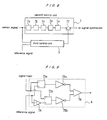
- FIGS. 7A through 7D are schematic views showing a modified example of the signal generator 7d.
- the signal generator 7d shown in FIG. 6 comprises several comparators and operational amplifiers.
- two operational amplifiers i.e., a comparator 77 including an operational amplifier and an inverting amplifier (inverter) 78 including an operational amplifier, can constitute a circuit for the equivalent function.
- the comparator 77 comprises nonlinear circuit components having input/output characteristics as shown in FIG. 7B or 7C . As shown in FIG. 7D , a rectangular wave signal 5 oscillating between the positive and negative sides with respect to zero volt can be generated, with an extremely simple circuit, from an input signal of a sine wave 1 by the comparator 77 having such input/output characteristics. As in the case of the circuit shown in FIG. 6 , only a frequency component and a phase component of the sensor signal can be transmitted downstream without its amplitude component being transmitted downstream.
- FIG. 8 shows an example in which a signal switch 7f is provided at the downstream side of the gain adjustor 7e in the second control unit 7, and a third control unit 9 is further provided.
- a sensor signal is compared with a reference signal, and when the sensor signal is more than a reference value, i.e., when whirling is greater than a predetermined value (reference value), the signal switch 7f is turned on.
- the signal switch 7f for switching on and off a flow of a signal in the second control unit 7, and the third control unit 9 for comparing the sensor signal of the displacement sensors 2a, 2b with the reference signal in order to turn the signal switch 7f on or off. Only when the sensor signal is more than a predetermined reference value, the signal switch 7f is turned on in order to add the output signal of the second control unit 7 to the output signal of the first control unit 5.
- FIG. 9 shows an example of a configuration of the third control unit 9.
- the third control unit 9 comprises comparators 73a, 73b, an inverting amplifier 74, inverters 75a, 75b, and an adder 76.
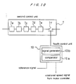
- FIG. 10 shows an example having a fourth control unit 10 which compares a voltage signal proportional to a rotational speed from a motor controller with a reference signal to thus turn on a signal switch 7f when the voltage signal is more than the reference signal.
- the fourth control unit 10 comprises a comparator 10a for comparing an actual rotational speed signal with the reference signal, and a signal generator 10b for generating an ON-OFF command signal to be inputted into the signal switch 7f provided in the second control unit 7 for switching on and off a flow of the signal.
- the signal switch 7f in the second control unit 7 is turned on and off based on the sensor signal.
- the signal switch 7f in the second control unit 7 can be turned on and off based on the rotational speed signal from the motor controller. Specifically, when the rotational speed of the motor is greater than a predetermined value, the signal switch 7f is turned on and off
- FIGS. 11A through 11C show modified examples of configurations of the second control unit.
- a rotational frequency component extractor 7b' which is a filter having the same function as the rotational frequency signal extractor 7b, is provided at the downstream side of the gain adjustor 7e in the second control unit 7.
- a rectangular wave signal can be converted into a low-order sine wave signal synchronized with a rotational frequency.
- the effect of suppressing whirling of the rotor is somewhat lower than that in a case where a rectangular wave signal is inputted as a control output into the power amplifier.
- an electric current of a harmonic component can be prevented from flowing, it is not necessary to excite higher modes of the rotor.
- FIG. 11B shows an embodiment in which the rotational frequency component extractor 7b' and the gain adjustor 7e in FIG. 11A are interchanged with each other.
- FIG. 11C shows an embodiment in which the signal switch 7f for switching on and off a flow of a signal shown in FIG. 8 is provided in the second control unit 7. Further, if an external force having a natural frequency not synchronized with the rotational speed acts on the rotor, the rotational frequency signal extractors 7b, 7b' in the second control unit 7 may be used as extractors of the natural frequency signal.
- FIG. 12 shows an embodiment having a fifth control unit 11 which monitors a sensor signal, and compares the amplitude of the sensor signal at the time when the signal switch 7f in the second control unit 7 is turned on and the amplitude of the sensor signal at the time when the signal switch 7f is turned off, and hence sets the volume of the gain adjustor 7e.
- the fifth control unit 11 is adapted to compare the amplitude of the sensor output at the time when the signal switch 7f in the second control unit 7 is turned off, with the amplitude of the sensor output at the time when the signal switch 7f is turned on, for thereby changing a set value of a gain in the gain adjustor 7e.
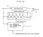
- FIG. 13 shows an embodiment having a sixth control unit 12.
- a voltage signal proportional to the rotational speed from the motor controller and the sensor signal are inputted into the sixth control unit 12, and phase adjustment values have been set beforehand for each of rotational speeds.
- a phase adjustment value corresponding to the rotational speed of the motor is set for the phase adjustor 7c.
- a filter circuit for changing the frequency by varying the voltage is used as the rotational frequency component extractor 7b. This configuration permits the frequency component corresponding to the rotational speed of the motor to be extracted.
- FIG. 14 shows an embodiment in which the sixth control unit 12 has a built-in storage for measuring and storing the transfer characteristics (gain, phase) of an output signal from the displacement sensor relative to an input signal for a power amplifier in a conventional servo control configuration, and reads a phase adjustment amount corresponding to the rotational speed of the motor from the stored data, and sets a phase adjustment amount for the phase adjustor 7c.
- FIGS. 15A through 15C show a modified example of the sixth control unit 12.
- data on the transfer characteristics of the magnetic bearing are stored with the storage.
- the sixth control unit shown in FIGS. 15A through 15C is simulation result of the transfer characteristics of a magnetic bearing by use of an analog circuit. Specifically, as shown in FIG. 15A , two primary filter circuits, each comprising an operational amplifier and CR elements, are used in order to obtain gain characteristics as shown in FIG. 15B and phase characteristics as shown in FIG. 15C .
- the capacitor elements C' cut off a wide-range gain and stabilize the action of operational amplifiers.
- This circuit configuration is generally used as a derivative element for an ordinary PID control (phase lead circuit).
- the characteristics shown in FIGS. 15B and 15C are simulation results of the transfer characteristics of the magnetic bearing shown in FIG. 17 to be described later on. For example, a phase change of about 90 to about 100 degrees can be imparted for 50 Hz, and a phase change of about 65 degrees can be imparted for 25 Hz. In this range, a gain is almost flat as shown in FIG. 15B .
- FIG. 16 shows a prototype of a magnetically levitated spin dryer as a structural example of a motor body supported by a magnetic bearing.
- a radial magnetic bearing 32 in FIG. 16 was used.
- a rotating shaft 15 is axially supported by an axial magnetic bearing 33 and radially supported by the radial magnetic bearings 32, and rotationally driven by a motor 31.
- a wafer holder 35 located underneath accommodates twenty-five 8-inch wafers.
- a wafer W is supported at its outer periphery by three beams in total, i.e., two fixed bars and a detachable moving bar.
- FIG. 17 shows a measurement result of the characteristics (responses of displacement sensor outputs to power amplifier inputs) in a servo control system of one of the radial magnetic bearings.
- This result corresponds to R/S, the ratio of an external force (R) acting on the rotor as a disturbance to the corresponding displacement (S) of the rotor.
- the denominator is the sensor signal (S) from the displacement sensor, while the numerator is the signal (R) added to the power amplifier input signal for measurement.
- the horizontal axis represents frequencies, and the vertical axis represents gains and phases.
- the frequency range in which the spin dryer is actually operated is found to be 0 to 50 Hz (0 to 3,000 min -1 ), and the phase characteristics are found to be about 108 degrees at 50 Hz and about 65 degrees at 25 Hz.
- phase characteristics i.e., phase information at rotational operation frequencies.
- This phase information is a basis of an adjustment amount set for the phase adjustor in the second control unit.
- the output current (A) from the power amplifier in response to its input voltage (V) has nonlinearity, and if the input voltage increases, frequency responses expressed by gain and phase may deteriorate remarkably. Specifically, when a whirling amplitude of the rotor becomes large, it is necessary to compensate the phase characteristics shown in FIG. 17 for the amount of deterioration in the frequency response of the power amplifier. It is also necessary to consider the frequency characteristics from the time when the output signal from the second control unit is inputted into the power amplifier, to the time when this signal finally acts on the rotor as a force. However, there is minimal influence at a relatively low frequency, and the values equivalent to the phase characteristics can be used. According to the results of the experiments, even if the compensation amount is an approximate value, an equivalent effect can be obtained.
- FIGS. 18A through 21B show the results of tests corresponding to a conventional open balance control.
- the purpose of these tests was to verify that an effect could be obtained when the phase difference between the control signal and the sensor signal to be added together corresponded to the value estimated based on the phase data of the frequency characteristics of the magnetic bearing stiffness shown in FIG. 17 .
- the control signal was generated by a commercially available signal generator.
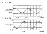
- FIGS. 18A through 19B show states when the value estimated based on the phase data shown in FIG. 17 , i.e., a phase difference of about 108 (deg), was imparted between the control signal and the sensor signal at a rotational speed of 3,000 min -1 (50 Hz).
- FIGS. 18A and 18B show waveforms over time when the control was turned off, while FIGS. 19A and 19B show waveforms over time when the control was turned on.
- FIGS. 18A and 19A show output signals from the displacement sensor, and FIGS. 18B and 19B show control signals. It is apparent from these drawings that when a phase difference of about 108 (deg) was imparted between the control signal and the sensor signal at a rotational speed of 3,000 min -1 (50 Hz), whirling of the rotor was suppressed.
- FIGS. 20A through 21B show states when the value estimated based on the phase data shown in FIG. 17 , i.e., a phase difference of about 64.8 (deg), was imparted between the control signal and the sensor signal at a rotational speed of 1,500 min -1 (25 Hz).
- FIGS. 20A and 20B show waveforms over time when the control was turned off, while FIGS. 21A and 21B show waveforms over time when the control was turned on.
- FIGS. 20A and 21A show output signals of the displacement sensor, and FIG. 20B and 21B control signals. It is apparent from these drawings that when a phase difference of about 64.8 (deg) was imparted between the control signal and the sensor signal at a rotational speed of 1,500 min -1 (25 Hz), whirling of the rotor was suppressed.
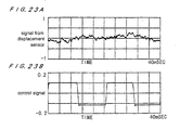
- FIGS. 22A through 23B The controlled magnetic bearing apparatus shown in FIGS. 2 through 6 was used to verify its effect of suppressing whirling of the rotor 1.
- the results are shown in FIGS. 22A through 23B .
- the rotational speed was 3,000 min -1
- FIGS. 22A and 22B show waveforms over time when the control was turned off
- FIGS. 23A and 23B show waveforms over time when the control was turned on.
- FIGS. 22A and 23A show output signals from the displacement sensor, and FIGS. 22B and 23B control signals. It is apparent from these drawings that the results equivalent to the results shown in FIGS. 18A through 19B were obtained.
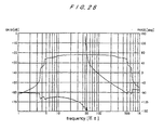
- FIG. 26 The transfer characteristics for the input signal and the output signal of the circuit used in these experiments are shown in FIG. 26.
- FIG. 26 shows that the phase adjustment was a lead angle of about 90 degrees to about 100 degrees at 3,000 min -1 (50 Hz).
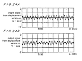
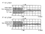
- FIGS. 24A through 25B show results of verification in a case where unbalance weights were increased, and where a conventional servo control led to a touchdown.
- the second control units were provided in each of two servo control systems on the X-axis and the Y-axis of the X-Y plane perpendicular to the rotating shaft.
- the rotational speed was 3,000 min -1 .
- FIGS. 24A and 24B show waveforms over time when the control was turned on.
- FIGS. 25A and 25B show waveforms over time when the control was turned on while the rotating shaft was being rotated with a touchdown.
- FIGS. 24A and 25A show waveforms of output signals from the displacement sensor on the X-axis over time.
- 24B and 25B show the waveforms of output signals from the displacement sensor on the Y-axis over time.
- the effect of suppressing whirling can be confirmed from these drawings.
- the phase amounts used in these experiments, in comparison with the phase data of FIG. 17 were found to be about 20 % more.
- whirling amplitude can be suppressed by adjusting the setting of the gain adjustor in the second control unit.
- the upper limit of this effect can be determined by the basic performance of the power amplifier and the degree of magnetic saturation of the magnetic path of the electromagnet.
- FIGS. 27 through 29C represent experimental data showing that even if the rotational speed changes sharply, the circuit configuration according to the present invention can fully suppress whirling of the rotor in the wafer spin dryer shown in FIG. 16 .
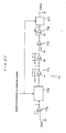
- FIG. 27 shows an example of a configuration of the second control unit 17.
- a sensor signal (input) is amplified by a buffer amplifier 17a, and a component of a signal corresponding to a rotational speed is extracted by a rotational speed signal extractor 17b.
- the model VT-2BPA of NF Corp. for example, is used as the extractor 17b.
- a phase adjustor 17c an adjustment amount for phase is imparted.
- the resulting signal is compared with a reference voltage by a comparator 17d, whereby amplitude information is blocked. Only the frequency and phase information corresponding to the rotational speed of the motor is transmitted downstream.
- Gain adjustors 17e, 17f adjust the gain, and the resulting signal is added to a signal output from the first control unit 5.
- the gain adjustor 17e is a fixed gain adjustor unrelated to the rotational speed.
- the gain adjustor 17f is a rotational speed proportional gain adjustor that gives a gain proportional to the rotational speed.
- the model AD633 of Analog Devices Inc., for example, is used as the gain adjustor 17f.
- FIGS. 28A and 28B show the situation of whirling of a rotor in a wafer spin dryer which is driven with a sharp rise in rotational speed from zero to a predetermined speed, operated for a certain time at a high speed (predetermined speed) of about 2,400 min -1 , and then sharply decelerated to a halt.
- predetermined speed a high speed
- FIGS. 28A through 28C when a balance control is turned on at the start of rotation, whirling of the rotor has a sufficient margin relative to a touchdown (TD) level even in sharply rising.
- TD touchdown
- the balance control is turned off at high rotational speed, whirling of the rotor increases up to the TD level, as illustrated by outputs from the displacement sensor shown in FIGS. 28A and 28B . Even at a sharp fall, further, the rotation of the rotor is stopped without considerable whirling.
- FIGS. 29 show the situations of whirling of the rotor at the time of sharp rise and sharp fall as in FIGS. 28 .
- the rotational speed was increased up to 3,000 min -1 .
- Whirling of the rotor has a sufficient margin relative to the touchdown (TD) level, similarly to the aforementioned case, and hence fully suppressed.
- TD touchdown
- the balance control is turned off, whirling grows up to the touchdown (TD) level at the sharp rise.
- the displacement sensor (No. 1) is a sensor provided in the radial magnetic bearing near the wafer holder.
- the displacement sensor (No. 2) is a sensor provided in the radial magnetic bearing distant from the wafer holder.
- the addition of the second control unit to each of the necessary control axes can improve the allowable support characteristics of the magnetic bearing with respect to the following problems:
- the motor is a bipolar induction motor
- a radial external force synchronized with the rotational speed is produced.
- an input electric power into the motor increases for maintaining a rotational movement following load fluctuation, whereby a more excessive radial external force is produced.
- a rolling bearing or a sliding bearing can support the rotor, even though there is a decrease in life.
- a contact bearing cannot be used.
- a spin dryer which dries a wafer or the like by high-speed rotation may have an excessive unbalance amount due to an object to be dried, compared with an ordinary magnetic bearing supporting stiffness.
- a magnetic bearing may be desired to be used.
- the aforementioned problems may arise as well.
- a magnetic bearing for non-contact support may need to be used at a portion where a conventional rolling bearing or the like has been used, it is difficult to incorporate a magnetic bearing of a necessary and sufficient size, because the entire space, the space for the bearing, and the structure of the rotor have already been fixed.
- a method which can solve such problems, and broaden the limiting performance of a magnetic bearing.
- whirling of a rotor supported by a magnetic bearing and having an excessive unbalance amount can be suppressed based on only a signal from a displacement sensor used for levitating position control of the rotor.
- the present invention can be applied to other cases in addition to a disturbance synchronized with a rotational speed.
- the present invention is effective as a means for enhancing a stiffness of a magnetic bearing relative to a periodical disturbance.
- the present invention relates to a controller for a magnetic bearing in an apparatus using the magnetic bearing as a means for supporting a rotor. Therefore, the present invention can be utilized for a controller of a magnetic bearing which magnetically levitates and supports a rotating shaft of a magnetically levitated spin dryer used in a semiconductor fabrication device, for example.
Landscapes
- Engineering & Computer Science (AREA)
- General Engineering & Computer Science (AREA)
- Mechanical Engineering (AREA)
- Physics & Mathematics (AREA)
- Electromagnetism (AREA)
- Magnetic Bearings And Hydrostatic Bearings (AREA)
Applications Claiming Priority (5)
| Application Number | Priority Date | Filing Date | Title |
|---|---|---|---|
| JP1872099 | 1999-01-27 | ||
| JP1872099 | 1999-01-27 | ||
| JP14470199A JP4036567B2 (ja) | 1999-01-27 | 1999-05-25 | 制御形磁気軸受装置 |
| JP14470199 | 1999-05-25 | ||
| PCT/JP2000/000272 WO2000045059A1 (en) | 1999-01-27 | 2000-01-21 | Controlled magnetic bearing device |
Publications (3)
| Publication Number | Publication Date |
|---|---|
| EP1065395A1 EP1065395A1 (en) | 2001-01-03 |
| EP1065395A4 EP1065395A4 (en) | 2004-11-17 |
| EP1065395B1 true EP1065395B1 (en) | 2009-05-27 |
Family
ID=26355446
Family Applications (1)
| Application Number | Title | Priority Date | Filing Date |
|---|---|---|---|
| EP00900852A Expired - Lifetime EP1065395B1 (en) | 1999-01-27 | 2000-01-21 | Controlled magnetic bearing device |
Country Status (7)
| Country | Link |
|---|---|
| US (2) | US6515387B1 (https=) |
| EP (1) | EP1065395B1 (https=) |
| JP (1) | JP4036567B2 (https=) |
| KR (1) | KR100622098B1 (https=) |
| DE (1) | DE60042253D1 (https=) |
| TW (1) | TW436586B (https=) |
| WO (1) | WO2000045059A1 (https=) |
Cited By (2)
| Publication number | Priority date | Publication date | Assignee | Title |
|---|---|---|---|---|
| CZ302646B6 (cs) * | 2009-08-26 | 2011-08-10 | Rieter Cz S.R.O. | Zpusob stabilizace levitujícího rotujícího elementu a zarízení pro stabilizaci levitujícího rotujícího elementu |
| EP3677785B1 (en) * | 2017-08-31 | 2024-09-11 | Edwards Japan Limited | Vacuum pump |
Families Citing this family (28)
| Publication number | Priority date | Publication date | Assignee | Title |
|---|---|---|---|---|
| AU2003278949A1 (en) * | 2002-09-23 | 2004-04-08 | Auburn University | A ring-spinning system for making yarn having a magnetically-elevated ring |
| JP4476694B2 (ja) * | 2003-06-25 | 2010-06-09 | 株式会社荏原製作所 | 磁気軸受装置および磁気軸受装置を備えた流体機械 |
| EP1621785A1 (en) * | 2004-07-30 | 2006-02-01 | Mecos Traxler AG | Method and apparatus for controlling a magnetic bearing device |
| DE102005001494A1 (de) * | 2005-01-12 | 2006-07-20 | Siemens Ag | Regelverfahren für eine Magnetlagerung und hiermit korrespondierende Einrichtung |
| EP1904975A4 (en) * | 2005-07-12 | 2014-05-14 | Technion Res & Dev Foundation | SYSTEM AND METHOD FOR THE ACTIVE DETECTION OF ASYMMETRY IN ROTATING STRUCTURES |
| WO2008075269A2 (en) * | 2006-12-19 | 2008-06-26 | Koninklijke Philips Electronics, N.V. | Control system and method for negative damping compensation in magnetic levitation |
| EP2006556B1 (en) * | 2007-06-18 | 2013-11-13 | Mecos Traxler AG | Recovery of impact in a magnetic bearing device |
| KR20110014590A (ko) * | 2008-04-17 | 2011-02-11 | 신크로니, 아이엔씨. | 저-손실 금속 회전자를 구비한 고속 영구자석 모터 및 발전기 |
| CA2721818A1 (en) | 2008-04-18 | 2009-11-19 | Synchrony, Inc. | Magnetic thrust bearing with integrated electronics |
| US9583991B2 (en) * | 2009-06-24 | 2017-02-28 | Synchrony, Inc. | Systems, devices, and/or methods for managing magnetic bearings |
| DE102009029129A1 (de) * | 2009-09-02 | 2011-03-03 | BSH Bosch und Siemens Hausgeräte GmbH | Kältegerät mit einer Halteklammer für einen Lüftermotor |
| CN102947606B (zh) * | 2010-06-21 | 2015-08-19 | 英派尔科技开发有限公司 | 影响磁轴承中的磁场的系统 |
| US8987959B2 (en) | 2010-06-23 | 2015-03-24 | Dresser-Rand Company | Split magnetic thrust bearing |
| CN102107375B (zh) * | 2010-11-26 | 2013-01-02 | 北京工业大学 | 一种基于负刚度原理的磨削工艺系统刚度补偿机构 |
| US9633890B2 (en) * | 2011-12-16 | 2017-04-25 | Lam Research Ag | Device for treating surfaces of wafer-shaped articles and gripping pin for use in the device |
| US9250017B2 (en) | 2012-03-16 | 2016-02-02 | Jerry D. Miller | Magnet supported rotary drum dryer |
| FR2997465B1 (fr) * | 2012-10-31 | 2015-04-17 | Ge Energy Power Conversion Technology Ltd | Palier magnetique actif comprenant des moyens d'amortissement des deplacements radiaux d'un arbre d'une machine tournante |
| US9197110B2 (en) * | 2013-03-14 | 2015-11-24 | Lawrence Livermore National Security, Llc | Electrostatic stabilizer for a passive magnetic bearing system |
| EP2818739B1 (en) * | 2013-06-28 | 2018-06-13 | Skf Magnetic Mechatronics | Improved active magnetic bearings control system |
| US9410554B2 (en) | 2014-04-04 | 2016-08-09 | Solar Turbines Incorporated | Controlling a gas compressor having multiple magnetic bearings |
| EP2933512B1 (en) * | 2014-04-14 | 2017-06-14 | ABB Schweiz AG | Magnetic bearing arrangement and method of operating a magnetic bearing arrangement |
| JP7119312B2 (ja) * | 2017-09-04 | 2022-08-17 | 株式会社島津製作所 | 磁気軸受制御装置および真空ポンプ |
| JP7093683B2 (ja) * | 2018-06-15 | 2022-06-30 | 川崎重工業株式会社 | 磁気軸受制御装置および磁気軸受制御方法 |
| CN109854622B (zh) * | 2019-03-26 | 2020-04-28 | 中国船舶科学研究中心(中国船舶重工集团公司第七0二研究所) | 一种基于智能材料可控制轴系径向振动的主动磁轴承系统 |
| DE102019112735A1 (de) * | 2019-05-15 | 2020-11-19 | Maschinenfabrik Rieter Ag | Verfahren zur Identifikation eines Spinnrotors an einer Rotorspinnmaschine sowie Rotorspinnmaschine |
| CN112460146A (zh) * | 2019-09-06 | 2021-03-09 | 北京亚之捷环保科技有限责任公司 | 一种主动式磁悬浮转子跌落保护系统 |
| KR102371862B1 (ko) * | 2020-06-25 | 2022-03-08 | 숭실대학교 산학협력단 | 동축 와전류 변위 센서를 갖는 자기베어링 |
| CN115220444B (zh) * | 2022-06-28 | 2025-02-11 | 中国科学院自动化研究所 | 一种基于模糊人工势场技术的水下机器人避障控制方法 |
Family Cites Families (24)
| Publication number | Priority date | Publication date | Assignee | Title |
|---|---|---|---|---|
| FR2336603A1 (fr) * | 1975-12-24 | 1977-07-22 | Europ Propulsion | Dispositif d'amortissement des frequences critiques d'un rotor suspendu magnetiquement |
| JPS5989821A (ja) | 1982-11-11 | 1984-05-24 | Seiko Instr & Electronics Ltd | 制御形磁気軸受装置 |
| FR2561738B1 (fr) * | 1984-03-26 | 1986-08-22 | Europ Propulsion | Procede et dispositif de reduction des vibrations des machines tournantes equipees d'une suspension magnetique active |
| JPS60245443A (ja) * | 1984-05-18 | 1985-12-05 | Ntn Toyo Bearing Co Ltd | 制御式ラジアル磁気軸受装置 |
| JPS6166540A (ja) * | 1984-09-08 | 1986-04-05 | Ntn Toyo Bearing Co Ltd | 磁気軸受の制御装置 |
| JPS61218427A (ja) * | 1985-03-25 | 1986-09-27 | Mitsubishi Electric Corp | 車両の振動制御装置 |
| US4795927A (en) * | 1986-05-02 | 1989-01-03 | Mitsubishi Jukogyo Kabushiki Kaisha | Control system for a magnetic type bearing |
| JPH0637895B2 (ja) | 1986-09-12 | 1994-05-18 | 株式会社日立製作所 | 電磁軸受制御装置 |
| JPS63285321A (ja) | 1987-05-18 | 1988-11-22 | Ebara Corp | 不釣り合い振動及び同期妨害振動の防止制御方式 |
| JPH01116318A (ja) * | 1987-10-28 | 1989-05-09 | Natl Aerospace Lab | 能動形磁気軸受 |
| EP0364993B1 (en) * | 1988-10-21 | 1996-01-24 | Ebara Corporation | Magnetic bearing system |
| JPH0720359B2 (ja) * | 1990-03-16 | 1995-03-06 | 株式会社荏原製作所 | 回転体のアンバランス修正装置 |
| JPH0419422A (ja) | 1990-05-11 | 1992-01-23 | Mitsui Eng & Shipbuild Co Ltd | 磁気軸受制御装置 |
| JP3087771B2 (ja) * | 1991-04-19 | 2000-09-11 | 株式会社安川電機 | 電流制御装置 |
| JP2565438B2 (ja) | 1991-09-20 | 1996-12-18 | 株式会社日立製作所 | 電磁軸受制御装置 |
| JP3322932B2 (ja) | 1992-03-09 | 2002-09-09 | 株式会社日立製作所 | 磁気軸受制御装置 |
| DE69319004T2 (de) * | 1992-03-09 | 1998-12-24 | Hitachi, Ltd., Tokio/Tokyo | Verfahren und Gerät zur Steuerung eines Magnetlagers |
| DE4216481A1 (de) * | 1992-05-19 | 1993-12-02 | Forschungszentrum Juelich Gmbh | Magnetlagerregler |
| JP3135410B2 (ja) * | 1993-04-14 | 2001-02-13 | 光洋精工株式会社 | 磁気軸受装置 |
| JP3226686B2 (ja) | 1993-12-08 | 2001-11-05 | セイコーインスツルメンツ株式会社 | 磁気軸受及び該磁気軸受のバランス調整方法 |
| FR2716700B1 (fr) * | 1994-02-28 | 1996-05-15 | Mecanique Magnetique Sa | Palier magnétique actif à auto-détection de position. |
| US5736801A (en) * | 1995-08-18 | 1998-04-07 | Ebara Corporation | Filter circuit and control circuit for controlling a rotor |
| EP0853735A1 (de) * | 1995-10-06 | 1998-07-22 | Sulzer Turbo AG | Rotodynamische maschine zur förderung eines fluides |
| JP3591111B2 (ja) * | 1996-02-29 | 2004-11-17 | 松下電器産業株式会社 | 磁気軸受制御装置 |
-
1999
- 1999-05-25 JP JP14470199A patent/JP4036567B2/ja not_active Expired - Lifetime
-
2000
- 2000-01-21 DE DE60042253T patent/DE60042253D1/de not_active Expired - Fee Related
- 2000-01-21 US US09/647,169 patent/US6515387B1/en not_active Expired - Fee Related
- 2000-01-21 KR KR1020007010700A patent/KR100622098B1/ko not_active Expired - Fee Related
- 2000-01-21 EP EP00900852A patent/EP1065395B1/en not_active Expired - Lifetime
- 2000-01-21 WO PCT/JP2000/000272 patent/WO2000045059A1/ja not_active Ceased
- 2000-01-25 TW TW089101141A patent/TW436586B/zh not_active IP Right Cessation
-
2002
- 2002-12-11 US US10/316,048 patent/US6809449B2/en not_active Expired - Fee Related
Cited By (2)
| Publication number | Priority date | Publication date | Assignee | Title |
|---|---|---|---|---|
| CZ302646B6 (cs) * | 2009-08-26 | 2011-08-10 | Rieter Cz S.R.O. | Zpusob stabilizace levitujícího rotujícího elementu a zarízení pro stabilizaci levitujícího rotujícího elementu |
| EP3677785B1 (en) * | 2017-08-31 | 2024-09-11 | Edwards Japan Limited | Vacuum pump |
Also Published As
| Publication number | Publication date |
|---|---|
| JP4036567B2 (ja) | 2008-01-23 |
| TW436586B (en) | 2001-05-28 |
| KR100622098B1 (ko) | 2006-09-07 |
| US6809449B2 (en) | 2004-10-26 |
| EP1065395A4 (en) | 2004-11-17 |
| US20030080638A1 (en) | 2003-05-01 |
| US6515387B1 (en) | 2003-02-04 |
| EP1065395A1 (en) | 2001-01-03 |
| DE60042253D1 (de) | 2009-07-09 |
| JP2000283159A (ja) | 2000-10-13 |
| WO2000045059A1 (en) | 2000-08-03 |
| KR20010042206A (ko) | 2001-05-25 |
Similar Documents
| Publication | Publication Date | Title |
|---|---|---|
| EP1065395B1 (en) | Controlled magnetic bearing device | |
| Peng et al. | A two-stage synchronous vibration control for magnetically suspended rotor system in the full speed range | |
| US5202824A (en) | Rotating force generator for magnetic bearings | |
| Bi et al. | Automatic learning control for unbalance compensation in active magnetic bearings | |
| EP0281632B1 (en) | Electromagnetic bearing controller | |
| Zheng et al. | Active balancing control of AMB-rotor systems using a phase-shift notch filter connected in parallel mode | |
| Polajžer et al. | Decentralized PI/PD position control for active magnetic bearings | |
| Sun et al. | Filter cross-feedback control for nutation mode of asymmetric rotors with gyroscopic effects | |
| US4935838A (en) | Structural magnetic vibration controller and method for actively controlling vibrations on stationary components of rotary machinery | |
| He et al. | Reduction of the high-speed magnetically suspended centrifugal compressor harmonic vibration using cascaded phase-shifted notch filters | |
| Grochmal et al. | Precision tracking of a rotating shaft with magnetic bearings by nonlinear decoupled disturbance observers | |
| Ye et al. | Vibration suppression for active magnetic bearings using adaptive filter with iterative search algorithm | |
| Sun et al. | Vibration suppression of magnetic bearing system based on active disturbance rejection control with generalized integrator extend state observer | |
| CN116755482A (zh) | 一种四自由度磁悬浮飞轮转子振动抑制的控制方法 | |
| JPS6166541A (ja) | 制御式ラジアル磁気軸受装置 | |
| Ritonja et al. | Active magnetic bearings control | |
| Hongphan et al. | Control system design for low power magnetic bearings in a flywheel energy storage system | |
| Xuan et al. | Magnetic bearing application by time delay control | |
| JP2957222B2 (ja) | 能動軸受のロータ支持制御装置 | |
| Prasad et al. | Modelling and Control of Power-Converter-Fed Electromagnetic Bearing | |
| Duan et al. | Robust control of a magnetic-bearing flywheel using dynamical compensators | |
| Abulrub et al. | Experiments on ROLAC to recover rotor position following contact | |
| Wang et al. | Integrated suspending and rotating controller based on TMS320F28377D for magnetically suspended rotor | |
| JPS62258221A (ja) | 磁気軸受の制御方式 | |
| Zhu et al. | A feed-forward control strategy for compensating rotor vibration of six-pole radial hybrid magnetic bearing with fuzzy adaptive filter |
Legal Events
| Date | Code | Title | Description |
|---|---|---|---|
| PUAI | Public reference made under article 153(3) epc to a published international application that has entered the european phase |
Free format text: ORIGINAL CODE: 0009012 |
|
| 17P | Request for examination filed |
Effective date: 20000928 |
|
| AK | Designated contracting states |
Kind code of ref document: A1 Designated state(s): AT BE CH CY DE DK ES FI FR GB GR IE IT LI LU MC NL PT SE |
|
| RBV | Designated contracting states (corrected) |
Designated state(s): DE FR GB |
|
| A4 | Supplementary search report drawn up and despatched |
Effective date: 20041005 |
|
| RIC1 | Information provided on ipc code assigned before grant |
Ipc: 7F 16C 39/06 B Ipc: 7H 02K 7/09 B Ipc: 7G 05D 3/12 B Ipc: 7F 16C 32/04 A |
|
| 17Q | First examination report despatched |
Effective date: 20070604 |
|
| GRAP | Despatch of communication of intention to grant a patent |
Free format text: ORIGINAL CODE: EPIDOSNIGR1 |
|
| GRAS | Grant fee paid |
Free format text: ORIGINAL CODE: EPIDOSNIGR3 |
|
| GRAA | (expected) grant |
Free format text: ORIGINAL CODE: 0009210 |
|
| AK | Designated contracting states |
Kind code of ref document: B1 Designated state(s): DE FR GB |
|
| REG | Reference to a national code |
Ref country code: GB Ref legal event code: FG4D |
|
| REF | Corresponds to: |
Ref document number: 60042253 Country of ref document: DE Date of ref document: 20090709 Kind code of ref document: P |
|
| PLBE | No opposition filed within time limit |
Free format text: ORIGINAL CODE: 0009261 |
|
| STAA | Information on the status of an ep patent application or granted ep patent |
Free format text: STATUS: NO OPPOSITION FILED WITHIN TIME LIMIT |
|
| 26N | No opposition filed |
Effective date: 20100302 |
|
| GBPC | Gb: european patent ceased through non-payment of renewal fee |
Effective date: 20100121 |
|
| REG | Reference to a national code |
Ref country code: FR Ref legal event code: ST Effective date: 20100930 |
|
| PG25 | Lapsed in a contracting state [announced via postgrant information from national office to epo] |
Ref country code: FR Free format text: LAPSE BECAUSE OF NON-PAYMENT OF DUE FEES Effective date: 20100201 |
|
| PG25 | Lapsed in a contracting state [announced via postgrant information from national office to epo] |
Ref country code: DE Free format text: LAPSE BECAUSE OF NON-PAYMENT OF DUE FEES Effective date: 20100803 |
|
| PG25 | Lapsed in a contracting state [announced via postgrant information from national office to epo] |
Ref country code: GB Free format text: LAPSE BECAUSE OF NON-PAYMENT OF DUE FEES Effective date: 20100121 |