EP1064543B1 - Dünnschichtchromatographiegerät - Google Patents
Dünnschichtchromatographiegerät Download PDFInfo
- Publication number
- EP1064543B1 EP1064543B1 EP99915513A EP99915513A EP1064543B1 EP 1064543 B1 EP1064543 B1 EP 1064543B1 EP 99915513 A EP99915513 A EP 99915513A EP 99915513 A EP99915513 A EP 99915513A EP 1064543 B1 EP1064543 B1 EP 1064543B1
- Authority
- EP
- European Patent Office
- Prior art keywords
- thin
- light
- emitting
- layer chromatography
- layer
- Prior art date
- Legal status (The legal status is an assumption and is not a legal conclusion. Google has not performed a legal analysis and makes no representation as to the accuracy of the status listed.)
- Expired - Lifetime
Links
- 238000004809 thin layer chromatography Methods 0.000 title claims abstract description 53
- 230000003287 optical effect Effects 0.000 claims abstract description 32
- 230000003595 spectral effect Effects 0.000 claims abstract description 17
- 238000005259 measurement Methods 0.000 claims abstract description 16
- 239000004020 conductor Substances 0.000 claims description 43
- 230000008878 coupling Effects 0.000 claims description 15
- 238000010168 coupling process Methods 0.000 claims description 15
- 238000005859 coupling reaction Methods 0.000 claims description 15
- 238000009826 distribution Methods 0.000 claims description 8
- 238000011835 investigation Methods 0.000 claims description 7
- 230000001678 irradiating effect Effects 0.000 claims 1
- 238000004587 chromatography analysis Methods 0.000 abstract description 5
- 230000033001 locomotion Effects 0.000 abstract description 5
- 238000010521 absorption reaction Methods 0.000 abstract description 4
- 238000004611 spectroscopical analysis Methods 0.000 abstract description 2
- 239000010409 thin film Substances 0.000 description 46
- 230000005540 biological transmission Effects 0.000 description 44
- 239000000835 fiber Substances 0.000 description 40
- 239000000126 substance Substances 0.000 description 26
- 238000005286 illumination Methods 0.000 description 12
- 238000001228 spectrum Methods 0.000 description 12
- 239000000203 mixture Substances 0.000 description 11
- 238000011156 evaluation Methods 0.000 description 10
- 238000004458 analytical method Methods 0.000 description 8
- 238000011161 development Methods 0.000 description 7
- 239000013307 optical fiber Substances 0.000 description 7
- 238000000926 separation method Methods 0.000 description 7
- 230000005526 G1 to G0 transition Effects 0.000 description 5
- 244000007853 Sarothamnus scoparius Species 0.000 description 5
- 238000001514 detection method Methods 0.000 description 5
- YZCKVEUIGOORGS-OUBTZVSYSA-N Deuterium Chemical compound [2H] YZCKVEUIGOORGS-OUBTZVSYSA-N 0.000 description 4
- 229910052805 deuterium Inorganic materials 0.000 description 4
- 239000000463 material Substances 0.000 description 3
- 238000000034 method Methods 0.000 description 3
- 238000012545 processing Methods 0.000 description 3
- 239000002904 solvent Substances 0.000 description 3
- RYYVLZVUVIJVGH-UHFFFAOYSA-N caffeine Chemical compound CN1C(=O)N(C)C(=O)C2=C1N=CN2C RYYVLZVUVIJVGH-UHFFFAOYSA-N 0.000 description 2
- 238000012937 correction Methods 0.000 description 2
- 238000006073 displacement reaction Methods 0.000 description 2
- 239000011521 glass Substances 0.000 description 2
- 229920000728 polyester Polymers 0.000 description 2
- 239000010453 quartz Substances 0.000 description 2
- 230000005855 radiation Effects 0.000 description 2
- 230000035945 sensitivity Effects 0.000 description 2
- VYPSYNLAJGMNEJ-UHFFFAOYSA-N silicon dioxide Inorganic materials O=[Si]=O VYPSYNLAJGMNEJ-UHFFFAOYSA-N 0.000 description 2
- 230000001629 suppression Effects 0.000 description 2
- 229920006303 teflon fiber Polymers 0.000 description 2
- WFKWXMTUELFFGS-UHFFFAOYSA-N tungsten Chemical compound [W] WFKWXMTUELFFGS-UHFFFAOYSA-N 0.000 description 2
- 229910052721 tungsten Inorganic materials 0.000 description 2
- 239000010937 tungsten Substances 0.000 description 2
- 239000004593 Epoxy Substances 0.000 description 1
- LPHGQDQBBGAPDZ-UHFFFAOYSA-N Isocaffeine Natural products CN1C(=O)N(C)C(=O)C2=C1N(C)C=N2 LPHGQDQBBGAPDZ-UHFFFAOYSA-N 0.000 description 1
- 241001632427 Radiola Species 0.000 description 1
- 230000009471 action Effects 0.000 description 1
- 229910052782 aluminium Inorganic materials 0.000 description 1
- XAGFODPZIPBFFR-UHFFFAOYSA-N aluminium Chemical compound [Al] XAGFODPZIPBFFR-UHFFFAOYSA-N 0.000 description 1
- 238000003705 background correction Methods 0.000 description 1
- 235000013361 beverage Nutrition 0.000 description 1
- 229960001948 caffeine Drugs 0.000 description 1
- VJEONQKOZGKCAK-UHFFFAOYSA-N caffeine Natural products CN1C(=O)N(C)C(=O)C2=C1C=CN2C VJEONQKOZGKCAK-UHFFFAOYSA-N 0.000 description 1
- 239000012876 carrier material Substances 0.000 description 1
- 230000008859 change Effects 0.000 description 1
- 239000003795 chemical substances by application Substances 0.000 description 1
- 238000005253 cladding Methods 0.000 description 1
- 230000001427 coherent effect Effects 0.000 description 1
- 238000007405 data analysis Methods 0.000 description 1
- 230000001419 dependent effect Effects 0.000 description 1
- 230000035418 detection of UV Effects 0.000 description 1
- 239000006185 dispersion Substances 0.000 description 1
- 239000003814 drug Substances 0.000 description 1
- 230000008030 elimination Effects 0.000 description 1
- 238000003379 elimination reaction Methods 0.000 description 1
- 239000003480 eluent Substances 0.000 description 1
- 238000005516 engineering process Methods 0.000 description 1
- 239000003365 glass fiber Substances 0.000 description 1
- 238000011065 in-situ storage Methods 0.000 description 1
- 238000003780 insertion Methods 0.000 description 1
- 230000037431 insertion Effects 0.000 description 1
- 238000007689 inspection Methods 0.000 description 1
- 235000015122 lemonade Nutrition 0.000 description 1
- 230000014759 maintenance of location Effects 0.000 description 1
- 230000007246 mechanism Effects 0.000 description 1
- 229910052751 metal Inorganic materials 0.000 description 1
- 239000002184 metal Substances 0.000 description 1
- 238000012856 packing Methods 0.000 description 1
- 239000000575 pesticide Substances 0.000 description 1
- 238000001292 planar chromatography Methods 0.000 description 1
- 238000005498 polishing Methods 0.000 description 1
- 238000011002 quantification Methods 0.000 description 1
- 229920005989 resin Polymers 0.000 description 1
- 239000011347 resin Substances 0.000 description 1
- 239000004576 sand Substances 0.000 description 1
- 239000004065 semiconductor Substances 0.000 description 1
- 230000007480 spreading Effects 0.000 description 1
- 229920003002 synthetic resin Polymers 0.000 description 1
- 239000000057 synthetic resin Substances 0.000 description 1
- 238000004454 trace mineral analysis Methods 0.000 description 1
- 238000002211 ultraviolet spectrum Methods 0.000 description 1
- 238000010200 validation analysis Methods 0.000 description 1
Images

Classifications
-
- G—PHYSICS
- G01—MEASURING; TESTING
- G01N—INVESTIGATING OR ANALYSING MATERIALS BY DETERMINING THEIR CHEMICAL OR PHYSICAL PROPERTIES
- G01N30/00—Investigating or analysing materials by separation into components using adsorption, absorption or similar phenomena or using ion-exchange, e.g. chromatography or field flow fractionation
- G01N30/90—Plate chromatography, e.g. thin layer or paper chromatography
- G01N30/95—Detectors specially adapted therefor; Signal analysis
Definitions
- the present invention relates to a thin layer chromatography device according to the preamble of claim 1.
- Thin layer chromatography is a common technique for the separation and analysis of substance mixtures. Doing so stationary phase as a thin layer on a suitable carrier made of glass, polyester, aluminum or the like. The The mixture of substances to be examined is at a starting point or a starting line on the stationary phase. Then the thin-layer plate is developed. This will be a mobile Phase as eluent, for example by adjusting the thin-layer plate in a trough chamber, at the start line or the Starting point brought from where the mobile phase begins, in particular by the capillary action of the stationary phase over the To run thin film. The mobile phase can be the one in it well soluble portions of the substance mixture to be examined take the thin film board with you. The less soluble components remain on the stationary phase.
- the required analysis of the developed thin layer chromatography plates usually takes place optically with thin-layer chromatography devices, in which the thin-layer plate with Light is irradiated and with which can be examined, how the incident light changes through the thin film plate becomes.
- the present invention is more concerned with such optical thin layer chromatography device and it is not relevant whether the actual application and development of the Thin-layer plate is made in the device itself; further it is irrelevant whether the carrier is rigid or flexible made of glass, polyester or the like is made as long as it is an optical one Examination of the developed chromatogram is accessible.
- the optical determination of which substances are present in the chromatogram can on the one hand be based on the location that a particular Part of the mixture of substances to be examined the thin-film board has reached during development, and on the other hand on its optical properties, i.e. the absorbency of the substance, its fluorescent properties, etc.
- An exact examination therefore requires a high spatial resolution as well as an accurate spectral investigation.
- Measurements with such systems are carried out in a variety of ways Publications, e.g. A. N. Diaz and F. Garcia Sanchez in “Fiber optic fluorescence scanning in thin layer chromatography “in” Instrumentation Science and Technology, 22 (3), 273-281 (1994) "; A.N. Diaz” Fiber-optic remote sensor for in situ fluorimetric quantification in thin-layer chromatography " in Analytica Chimica Acta, 255 (1991) 297-303.
- Another device is from “Determination of Reflectance of Pesticide Spots on Thin-Layer Chromatograms Using Fiber Optics" by M. Beroza, K.R. Hill and K.H. Norris in Analytical Chemistry, Vol. 40, 1608-1613 (1968). It is suggested there a thin-layer plate with stochastically arranged To scan Y light guides. The foot of the Y fibers becomes a thin layer plate the first arm to a light source and the other Arm led to an optical examination device. It is a reading head for plate scanning and a head for reference measurement required on an adjacent free path.
- a problem with such thin layer chromatography devices consists in the uneven distribution of the substances over the areas to which they are located on the thin layer plate at the Development.
- the focus is in the center of an area highest and takes to the edges of the stain from.
- a disadvantage of the measures described above, with which the uneven substance distribution over the stain compensated is the reduced spatial resolution. she leads to poorer separation performance for a given amount of substance or with a limited amount of substances to a deteriorated Detection sensitivity.
- the light source can be one Incandescent light source with a small aperture or preferred a semiconductor light source, e.g. B. include an LED.
- EP 0 060 709 B1 describes a method and a device known for multidimensional real-time chromatography.
- the previously known system has first means for chromatographic Separate a sample by unknown composition into a first one Grouping of components based on the first Agent is a thin layer chromatographic plate can; second means for further separation of the components mentioned into a higher dimensional second grouping of components; third means for recognizing the components mentioned.
- the third means can be a linear multiphotodiode array which detects how a light source detects the eluting one Illuminated solvent on the thin film plate.
- the lighting can use a variety of light sources, which be used successively and at different wavelengths emit that specific for the unknown components sought are.
- a device in which a plurality of coherent parallel Light rays are used to determine the position of an object to determine is known from EP 0 669 515 A3.
- the well-known Device is used to in a channel or the like. the position of tree trunks or other elongated To determine objects.
- the present invention aims to innovate for the commercial To provide application and in particular, but not exclusively, a robust, compact thin-layer chromatography device to provide with high spectral and spatial resolution, with minor disturbances in particular due to ambient light and which is nevertheless inexpensive is to be produced.
- One idea of the invention is therefore the light guide to be arranged in a predetermined geometric orientation.
- the geometrical arrangement of the transmitting and receiving light guides to each other allows the overlap of the light spot, the is emitted by a transmission light guide with the field of view, which is detected by the receiving light guides to choose and make it controllable as desired.
- the regularity the arrangement which is due to the fact that broadcast and Receiving light guides also arranged geometrically with one another ensures that the overlap integrals of different, mutually assigned transmission and reception light guides correspond, which also applies if for certain purposes not all overlap integrals are exactly identical to each other but groups of mutually corresponding overlap integrals are present, for example when using several different ones Fiber types.
- the spatial resolution is suggested in the Arrangement due to the comparatively small overlap integral determined and not by the spot size of the entire illuminated TLC plate area.
- fields of view of the receiving light guide and light spots of the transmitting light guide adjustable partially overlap, with the Distance of the light guide to the thin-film plate can be changed can what by piezoelectric modulation or with mechanical Funds is possible.
- Transmitted light conductors are provided, which are linearly close together are lined up.
- the light spots of neighboring transmission light guides on the thin layer plate can almost overlap or be slightly spaced. In this case, one receives Receiving light guides preferably light from at least two transmission light guides.
- the rows are for setting the light spot overlap movable to each other by transmission light guides of different rows, for example by swiveling and / or translating a row others or away from them.
- An adjustable variable distance of the transmission light conductors within a series enables measurements with different The light spots overlap with one another or with respective ones Fields of vision and thus different spatial resolutions.
- Light sources in the transmission light guides facilitate implementation a desired illumination spectrum.
- One about the used spectral range provides approximately uniform intensity sure that those used in the optical inspection device Detectors not particularly in narrow spectral ranges intensive signals are overloaded.
- a desired one Illumination spectrum is also through with a single light source dispersive elements between light source and thin-film plate to achieve, or by different lengths of light guide.
- a refractive lens as a dispersive element also increases the Coupling efficiency in the transmission light guide.
- the coupling efficiency is also increased if a fiber jacket is present removed on the lamp side, roughly etched away and the ends several fibers optionally welded or in synthetic resin be poured.
- the thin-layer plate with all transmission light conductors at least almost the same intensity is between the light source and input side of the transmission light guide a diffuser or the like arranged.
- a plurality of optical ones Providing transmission light conductors is also preferred, or at least a plurality of optical receiving conductors such as at least twenty, but preferably between 50 and 100 receiving light guides intended.
- optical receiving light guides can be used for simultaneous Reception of transmitted through the thin film plate and of the thin-film plate or those located on the thin-film plate Substances remitted light can be arranged. Even if light is received simultaneously, each is unique optical examination facilities not mandatory. economical the ones intended for remission / fluorescence and transmission Receiving light guide to one and the same optical Examination device guided and evaluated there alternately.
- the light path between the optical examination device and thin-film plate using a chopper for example can be selectively sealed off alternately, or the Optical fibers are alternately in the optical examination device coupled. This provides a quasi-simultaneous evaluation instead of.
- a particularly preferred variant of the thin layer chromatography device each has at least one row of optical fibers and a row of receiving light guides, preferably with more than 10 each light guides arranged close to each other.
- each receiving light guide receives light several transmission fibers. This improves the optical evaluation by the examination facility.
- the transmitting and receiving light guides can be in different parallel rows are arranged, with an offset arrangement "on gap" between transmit and receive light guide row is preferred in order to achieve a better luminous efficiency.
- One with the same diameter for all transmitting and receiving light guides is not mandatory, which if necessary allows denser packing.
- quartz fibers for the detection of UV light
- Teflon fibers for the area above 250 nm.
- the light guide assembly can be made into a wide one Brooms can be arranged with 30 fibers, each 100 ⁇ m in diameter about 3.5 mm broom width and 50 fibers already 5.5 mm. Shading can be made at the edges, if this is because of a given thin film board only a small amount of material is too much. You can choose to do this the coupling of light into the outer transmission light guide the light source, the radiation on the plate, the radiation of light into the receiving light guide and / or the coupling of light from the receiving light guides into the optical examination device be suppressed.
- Transmitting and receiving light guides are preferred with one Stepper motor or the like moved relative to the thin-film plate, to scan a chromatographic path. Is preferred the plate moves with a rigid scanning head. This avoids changes the light transmission in the light guides through movement-related Variations in refractive index, for example in the case of kinks.
- the orientation of the thin layer plate is preferred with a CCD camera or the like is visually documented.
- a means of detection and / or compensation provided thin-film plates not lying parallel to the plane his.
- the distance can be used to determine the plate alignment of the transmitting and / or scanning head from the disk to each other spaced, unaffected by solvent and substance Set the plate as a white standard with reference measurements be determined.
- Such places are behind, for example Eluens running end of the outer tracks or laterally from the outer To find tracks.
- the reference measurement can be about the entire Determine light intensity in reflection. Is the intensity of the reflected light at the different, spaced Do not equal, so the plate is not parallel. A previously performed measurement can then be discarded or it a measurement to be carried out is suppressed.
- the transmitting and / or receiving light guide in The present arrangement can achieve small transmission light spots and thus high spatial resolutions the plate are guided; Distances are usually well below one millimeter, like some 100 ⁇ m.
- the correction prevents that through inclinations, like they already through grains of sand or could be caused under the thin film plate, Measurement errors occur.
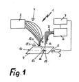
- a thin-layer chromatography device comprises a light source 2 to which a A large number of optical fibers 3 are coupled as transmission optical fibers are to the light on a developed thin film plate 4 to lead.
- the transmission light guides 3 throw a transmission light spot 13 on the thin-layer plate 4, which illuminates itself evenly elongated across the entire width of a chromatography web 10 stretches.
- Receiving light guide 5 are in the thin film plate so arranged.
- the receiving field of view 15 of the receiving light guide 5 overlaps at least partially with the transmitted light spot 13 as by the one representing the overlap integral blackened area 16 indicated, so that the field of view 15 retroreflected Remission and / or fluorescence light detected.
- the Receiving light guides 5 lead to an optical examination device 6, which with a central control and data processing unit 7 is connected.
- the control and data processing unit 7 controls an electrical displacement unit 8 like a stepper motor with which the thin-film plate 4 via a coupling mechanism 9 relative to the transmitting and receiving light guides 3 or 5 can be moved such that a Chromatography 10 moves under the light guides 3 and 5 becomes.
- the movement of the thin-layer plate 4 is preferably carried out by means of a stepper motor controlled by a 7 such as a PC 8 or the like.
- the light source 2 can be a deuterium lamp, a Tungsten lamp, a combined deuterium and tungsten lamp (Translucent lamp), a broadband high pressure lamp, a narrow band low pressure lamp a pulsed or continuous wave laser, e.g. Excimer laser, metal vapor laser, Nd-YAG laser, tunable lasers like ring lasers, also harmonic frequency multiplied, and act like that.
- a pulsed or continuous wave laser e.g. Excimer laser, metal vapor laser, Nd-YAG laser, tunable lasers like ring lasers, also harmonic frequency multiplied, and act like that.
- In the beam path between Light source and light coupling ends of the transmission light guide 3 can filter such as narrow band interference filter, band pass filter, Edge filters and the like and lenses for increasing the coupling efficiency and / or spreading discs for uniform Illumination of all transmission light guides 3 can be provided.
- the use of also in wide ultraviolet range of transparent light guides is advantageous.
- There can be light guides with a diameter of, for example 50 microns to 200 microns are used, being used for generation small spots of light on the thin layer chromatography plate with consequent better spatial resolution small fiber optic diameter are preferred.
- the light guides must not necessarily be round.
- coated fibers are used as transmission light guides 3, it is possible to etch away the fiber cladding at the end of the light source and the fiber ends for better utilization of the lamp intensity to weld, for example by means of a laser, or in transparent Pour in resin such as epoxy. If before such Arrangement a lens is attached, a uniform illumination of all fibers and thus one over the Row width at least almost constant illumination of the thin-film panel achieved.
- the fibers can if necessary with cylindrical lenses with focal lengths of, for example about 2.5 mm, Fresnel lenses or the like provided that the result of using lenses Dispersion does not interfere and a special light pattern the thin-layer plate is desired.
- the fiber ends can also be ground round or pointed or in a conventional way Way as cut or break edge without further measures be used. Polishing is also conceivable the fiber ends or the like.
- the transmission fiber ends are preferably together in one a few millimeters wide row arranged side by side and fixed in a holder 11, which according to arrow 12a Longitudinal axis pivotable and according to arrows 12b perpendicular to the thin-layer plate and parallel in the direction of the reception light guide row is too movable. Moving the transmitter light guide row parallel to the thin film plate and / or fluctuation of the Transmitter light guide row around the longitudinal axis (arrow 12a) changes that Overlap integral 16.
- the receiving light guide row can be fixed.
- a device is provided on the holder 11, with which the distance of the transmission light guides 3 to each other can be adjusted in series (not shown). Because of The small stroke required is a piezoelectric one Modulator can be used. This way the width of the illuminated path can be set.
- the thin film plate 4 is a pre-developed or in the Thin layer chromatography device of the present invention TLC plate.
- TLC plate The use of other carrier materials for the mobile phase except plates, such as flexible supports is also conceivable, but is for the present purposes subsumed under the term thin-film board.
- the receiving light guides 5 are side by side in a row a fixation 14 arranged in which the distance of the fibers to each other if necessary also as desired is adjustable. If the setting of the fiber spacing is about piezo-electrically modulated, the distance can e.g. of the controller 7 can be set.
- the diameter is the receiving light guide 5 smaller than the diameter of the transmission light guide 3.
- the reception light spot is smaller than the transmitted light spot and there will be the coupling of stray light further reduced what the signal to noise ratio improved, even if identical Diameters for transmit and receive light guides such a good one Low light suppression takes place that the thin layer chromatography device operated in normal use without darkening can be.
- the transmission light guides 5 lead to the optical examination device 6, which is a spectrometer to which the receiving light guide is coupled side by side are that they enter the entrance slit evenly and losslessly Illuminate without pinhole or the like.
- the optical examination device 6 which is a spectrometer to which the receiving light guide is coupled side by side are that they enter the entrance slit evenly and losslessly Illuminate without pinhole or the like.
- light guides directly on a dispersive element like a prism e.g. expensive and UV lenses that are often annoying due to reflections at the boundary layers should be avoided.
- a fixed light guide geometry at the spectrometer gap and on the thin-layer plate only requires a one-time and thus time-saving adjustment, but still allowed by the high reproducibility and the good coupling efficiency Signal resolutions of more than 14 bits also with conventional ones optical examination facilities.
- the thin layer chromatography device is operated as follows.
- the thin-layer plate is developed. Then becomes the thin-layer plate 4 in the thin-layer chromatography device placed.
- the overlap integral by swiveling the row 11 and moving the Rows 11 and 14 can be set.
- the pivoting vertically against the plate is kept so small that after Lambert's cosine law no relevant intensity losses occur.
- the overlap is for the desired spatial resolution set: The greater the overlap, the lower is the spatial resolution, but the usage efficiency of the incident light increases.
- Displacement unit 8 is in the Starting position moved.
- the light source 2 is excited.
- Light passes through the Transmission light guide 3 in the form of a narrow, brightly lit Slot on the thin film plate 4, where it is the width of a entire chromatographic path 10 is illuminated. if necessary is the total intensity of the thin-film plate reflected light at spaced, not from Solvents and the like, touched points measured. Is the if the white light reference is the same at the points, the Thin film plate 4 flat. Instead of the white light reference is a reference to certain spectral components is also possible.
- the separated mixture of substances on the chromatography path 10 absorbs in certain locations in certain spectral ranges Light and fluoresces in other spectral ranges. That so changed light, which emits from the thin-film plate gets, at least in part, into the receiving light guide 5, because the transmission light spots and the reception fields of view are adjustable overlap.
- the light radiated into the receiving light guide 5 is transmitted through the receiving light guide to the optical examination device performed and broken down into its spectral components.
- the spectrum is detected in the spectrometer with a row of diodes is a quick record of the full spectrum possible.
- the data are processed by the control and processing unit 7 read out via appropriate signal electronics.
- the evaluation is possible in real time or later, preferably raw data, about the light intensities are stored.
- the Stepper motor 8 excited to the thin-film plate 4 - a defined Move further.
- the range of motion is determined according to the resolution ⁇ , which for a given one Investigation from both thin film plate development and can also be expected from the optical arrangement. It is preferred to have a resolution of about 100 ⁇ m (4 ⁇ ) Make a shift of about 50 ⁇ m. At typical development run heights of 50 mm there are 1000 spectra per lane. Since the measurement times are short due to the good background suppression can still be selected is a recording time per lane possible within approx. 60 seconds or less.
- the orientation of the thin-layer plate can also be added in a thin layer chromatography device e.g. with a CCD camera can be recorded and documented.
- the thin-layer plate is longitudinal their career direction was shifted to a spectrum of one this is not absolutely necessary. Rather, the plate can also run transversely to its direction be examined, especially if instead of a qualitative one Analysis a quantitative determination of a known Substance with known series of runs in a large number of samples should be done.
- a quantitative determination of a known Substance with known series of runs in a large number of samples should be done.
- multiple substance samples are taken placed next to each other on the plate in the X direction and developed in the orthogonal Y direction, so that a Mixture splitting in the Y direction results.
- the tracking of the substance to be determined i.e. the Y coordinate, up to which the different ones are plotted side by side in the X direction Rehearsals have been run.
- the transmitting and receiving light guide series is set to this Y position and in the X direction moved across all careers of the different samples. This is then particularly advantageous because the evaluation with a thin layer chromatography scanner one of the most time consuming operations of the entire analysis if a variety of careers must be evaluated. The high expenditure of time can through simultaneous or almost simultaneous evaluation only of a very short section of many careers considerably shortened become.
- the invention enables such an evaluation, because the transmit and receive light guide rows have a larger extension than have the sample spot on the individual track. Even with this application, an exact adjustment is not required. A use especially in the beverage industry, for example to determine the caffeine content of lemonades by quantitative thin layer chromatography is straightforward possible.
- the different light guide arrangements have different Local resolutions and different usage efficiencies of the incident light.
- the various expected Local resolutions for fibers with a diameter of 100 ⁇ m and at the luminous efficacy expected in the respective arrangement maximum overlap of transmitted and received light spots is in given in the table below.
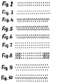
- transmitting and receiving light guides are each direct arranged side by side.
- transmit and receive light guide rows are against each other offset, so are on gap.
- FIG. 5 largely corresponds to FIG. 4, however, the transmission light guides X 1 are supplied with light from a first light source and the transmission light guides X 2 with light from a second light source. In this way, a desired illumination spectrum can be obtained.
- FIG. 6 largely corresponds to FIG. 5, but all reception light dividers are same and lead to the same spectrometer.
- Figure 7 shows an arrangement in which a row of receiving light guides arranged between two rows of transmission fibers is.
- the arrangement of a transmission light row would be analogous between two rows of receiving light guides possible and for fluorescence measurements because of the light output of practically 100% at one Local resolution of 200 ⁇ m advantageous for fibers of 100 ⁇ m.
- Figure 8 shows an example that by shading the outer Edge areas of the arrangement of FIG. 7 the width over which the thin-film plate is scanned, can be reduced.
- transmitters arranged in parallel could and receive light guide rows also in the row direction so shifted against each other that the respective outer light guide are unpaired. After that, there is excess at one end Transmission light guide and excess reception light guide at the other end is present and the effective broom width is reduced on the middle broom area, where there are still paired light guides available.
- Figure 9 largely corresponds to the arrangement of Figure 7, however transmit and receive light guides are set against each other on gap.
- FIGS. 10 to 12 show how light is emitted in the transmission light guide different light sources is coupled or how these alternating with different optical examination devices can be performed.
- Figure 14 shows the alternating arrangement of transmit and receive light guides in a row next to each other. Here too it is possible to simultaneously light from two lamps onto the thin film plate irradiate and / or light different optical To supply investigation facilities.
Landscapes
- General Health & Medical Sciences (AREA)
- General Physics & Mathematics (AREA)
- Life Sciences & Earth Sciences (AREA)
- Chemical & Material Sciences (AREA)
- Analytical Chemistry (AREA)
- Biochemistry (AREA)
- Immunology (AREA)
- Health & Medical Sciences (AREA)
- Pathology (AREA)
- Physics & Mathematics (AREA)
- Investigating Or Analysing Materials By Optical Means (AREA)
- Investigating, Analyzing Materials By Fluorescence Or Luminescence (AREA)
- Treatment Of Liquids With Adsorbents In General (AREA)
- Solid-Sorbent Or Filter-Aiding Compositions (AREA)
Description
- Figur 1
- ein Dünnschichtchromatographiegerät gemäß der vorliegenden Erfindung;
- Figuren 2 bis 14
- bevorzugte Anordnungen von Sendelichtleitern "x" und Empfangslichtleitern "c".
| Anordnung nach Figur | Ortsauflösung auf der Dünnschichtplatte (geschätzt) [µm] | Lichtausbeute (geschätzt) [%] |
| Figur 2 | 90 | 33 |
| Figur 3 | 105 | 35 |
| Figur 4 | 90 | 33 |
| Figur 5 | 90 | 33 |
| Figur 6 | 90 | 33 |
| Figur 7 | 200 | 100 |
| Figur 9 | 190 | 100 |
| Figur 10 | 190 | 100 |
| Figur 11 | 190 | 100 |
| Figur 12 | 190 | 100 |
| Figur 14 | 190 | 100 |
| Figur 15 | 160 | 36 |
Claims (20)
- Dünnschichtchromatographiegerät (1) mit
einer Mehrzahl optischer Sendelichtleiter (3)
zur Einstrahlung von Licht auf eine Dünnschichtplatte (4) und einer Mehrzahl optischer Empfangslichtleiter (5) um Licht von der Dünnschichtplatte einer optischen Untersuchungseinrichtung (6) zuzuleiten,
wobei Sende- und Empfangslichtleiter eine geordnete regelmäßige, geometrische Ausrichtung derart aufweisen,
daß sich Sendelichtleiter-Lichtflecken und Empfangslichtleiter-Sichtfeld zumindest partiell überlappen,
dadurch gekennzeichnet, daß ein Überlappungsintegral-Einstellmittel vorgesehen ist, mittels welchem das Überlappungsintegral von Sendelichtflecken und Empfangssichtfeld einstellbar ist. - Anspruch nach dem vorhergehenden Anspruch,
dadurch gekennzeichnet, daß die Sendelichtleiter zur gleichmäßigen Ausrichtung über eine Fleckenbreite angeordnet sind. - Dünnschichtchromatographiegerät nach dem vorhergehenden Anspruch,
dadurch gekennzeichnet, daß
das Überlappungsintegraleinstellmittel zur Einstellung des Lichtleiterabstandes zueinander und/oder zur Dünnschichtplatte ausgebildet ist. - Dünnschichtchromatographiegerät nach einem der vorhergehenden Ansprüche, worin zur geordneten geometrischen Ausrichtung Sendelichtleiter und/oder die Empfangslichtleiter eine Vielzahl, vorzugsweise mindestens 10 Sendeleiter dicht nebeneinander aufgereiht angeordnet sind, insbesondere linear und so dicht, daß die Lichtflecken benachbarter Sendelichtleiter auf der Dünnschichtplatte allenfalls um weniger als den Sichtfelddurchmesser eines Empfangslichtleiters beabstandet sind.
- Dünnschichtchromatographiegerät nach dem vorhergehenden Anspruch, worin wenigstens zwei allgemein parallele Sendelichtleiter-Reihen vorgesehen sind, deren Lichtflecken auf der Dünnschichtplatte allenfalls um weniger als den Sichtfelddurchmesser eines Empfangslichtleiters beabstandet sind.
- Dünnschichtchromatographiegerät nach einem der vorhergehenden Ansprüche, worin der Sendelichtleiter-Abstand einstellbar ist, insbesondere piezoelektrisch moduliert.
- Dünnschichtchromatographiegerät nach einem der vorhergehenden Ansprüche, mit einer Einkoppelvorrichtung zum eingangsseitigen Einkoppeln von Licht aus wenigstens zwei unterschiedlichen Lichtquellen bestimmter spektraler Intensität in die Sendelichtleiter.
- Dünnschichtchromatographiegerät nach dem vorhergehenden Anspruch, worin die Lichtquellen und/oder die Einkoppelvorrichtung und/oder die Sendelichtleiter so ausgelegt sind, daß aus zwei dünnschichtplattenseitig benachbarten Sendelichtleitern Licht unterschiedlicher spektraler Intensität auf die Dünnschichtplatte emittiert wird.
- Dünnschichtchromatographiegerät nach dem vorhergehenden Anspruch, worin einem oder mehreren Sendelichtleitern zur gezielten Beeinflussung der spektralen Verteilung auf die Dünnschichtplatte eingestrahlten Lichtes und/oder zur Erhöhung der Einkopplungseffizienz wenigstens ein dispersives Element zugeordnet ist, insbesondere ein Kantenfilter, ein Bandpaßfilter oder eine Ein- bzw. Auskoppellinse.
- Dünnschichtchromatographiegerät nach einem der vorhergehenden Ansprüche mit aufgereiht angeordneten Empfangslichtleitern, vorzugsweise mindestens 20, insbesondere bevorzugt zwischen 50 und 100 aufgereihten Empfangslichtleitern.
- Dünnschichtchromatographiegerät nach dem vorhergehenden Anspruch, worin Empfangslichtleiter zum simultanen Empfang von transmittiertem und remittiertem Licht angeordnet sind, insbesondere mit je mindestens einer Empfangslichtleiter-Reihe oberhalb und unterhalb der Dünnschichtplatte.
- Dünnschichtchromatographiegerät nach einem der vorhergehenden Ansprüche, worin die Sendelichtleiter und Empfangslichtleiter jeweils in Reihe angeordnet sind.
- Dünnschichtchromatographiegerät nach Anspruch 12, worin Sende- und Empfangslichtleiter gemeinsam eine Reihe bilden, insbesondere mit an der Dünnschichtplatte endenden Y-Fasern oder mit alternierend angeordneten Sende- und Empfangslichtleitern.
- Dünnschichtchromatographiegerät nach Anspruch 12, worin Sende- und Empfangslichtleiter in parallelen Reihen angeordnet sind, insbesondere mit einer Empfangslichtleiter-Reihe zwischen zwei Sendelichtleiter-Reihen und bevorzugt versetzt gegen diese und/oder mit aufeinander zuweisend beidseits der Dünnschichtplatte angeordneten Sende- und Empfangslichtleiter-Reihen.
- Dünnschichtchromatographiegerät nach Anspruch 14, worin eine Sendelichtleiter-Reihe zwischen zwei Empfangslichtleiter-Reihen angeordnet ist und bevorzugt die optische Untersuchungseinrichtung für Fluoreszenzmessungen ausgebildet ist.
- Dünnschichtchromatographiegerät nach einem der vorhergehenden Ansprüche, worin Sende- und Empfangslichtleiter unterschiedliche Durchmesser besitzen, wobei insbesondere der/die Empfangslichtleiter-Durchmesser größer als der/die Sendelichtleiter-Durchmesser ist/sind.
- Dünnschichtchromatographiegerät nach einem der vorhergehenden Ansprüche mit einer Einstellvorrichtung zur Verringerung der verwendeten Sende- und/oder Empfangslichtleiterzahl.
- Dünnschichtchromatographiegerät nach einem der vorhergehenden Ansprüche mit einer Schrittmotorsteuerung zur Bewegung von Sende- und Empfangslichtleitern insbesondere gemeinsam relativ zur Dünnschichtplatte.
- Dünnschichtchromatographiegerät nach einem der vorhergehenden Ansprüche mit einer CCD-Kamera zur Dokumentation der Dünnschichtplattenausrichtung.
- Dünnschichtchromatographiegerät nach einem der vorhergehenden Ansprüche mit einem Mittel zur Feststellung und/oder zum Ausgleich nicht planparallel liegender Dünnschichtplatten.
Applications Claiming Priority (3)
| Application Number | Priority Date | Filing Date | Title |
|---|---|---|---|
| DE19811150A DE19811150C2 (de) | 1998-03-14 | 1998-03-14 | Dünnschichtchromatographiegerät |
| DE19811150 | 1998-03-14 | ||
| PCT/DE1999/000693 WO1999047914A1 (de) | 1998-03-14 | 1999-03-12 | Dünnschichtchromatographiegerät |
Publications (2)
| Publication Number | Publication Date |
|---|---|
| EP1064543A1 EP1064543A1 (de) | 2001-01-03 |
| EP1064543B1 true EP1064543B1 (de) | 2003-06-04 |
Family
ID=7860924
Family Applications (1)
| Application Number | Title | Priority Date | Filing Date |
|---|---|---|---|
| EP99915513A Expired - Lifetime EP1064543B1 (de) | 1998-03-14 | 1999-03-12 | Dünnschichtchromatographiegerät |
Country Status (6)
| Country | Link |
|---|---|
| US (1) | US6485687B1 (de) |
| EP (1) | EP1064543B1 (de) |
| AT (1) | ATE242479T1 (de) |
| CA (1) | CA2323537C (de) |
| DE (2) | DE19811150C2 (de) |
| WO (1) | WO1999047914A1 (de) |
Families Citing this family (10)
| Publication number | Priority date | Publication date | Assignee | Title |
|---|---|---|---|---|
| LU90565B1 (en) * | 2000-04-14 | 2001-10-15 | Europ Economic Community | Device for the detection of aflatoxins |
| NL1023680C2 (nl) * | 2003-06-17 | 2004-12-20 | Tno | Sensor met polymeren componenten. |
| DE102004021600A1 (de) * | 2004-05-03 | 2005-12-08 | Gretag-Macbeth Ag | Vorrichtung zur Inline-Überwachung der Druckqualität bei Bogenoffsetdruckmaschinen |
| CN103026224B (zh) * | 2010-05-27 | 2015-07-22 | 株式会社大赛璐 | 使用薄层层析的样品检测方法、薄层层析板及其制造方法 |
| WO2012019134A2 (en) | 2010-08-06 | 2012-02-09 | Brown University | Functionalized chromatographic materials and methods of making and using therefor |
| CN103076313B (zh) * | 2011-12-31 | 2014-10-22 | 长春吉大·小天鹅仪器有限公司 | 菊酯农药检测装置和方法 |
| CN102590161A (zh) * | 2012-01-16 | 2012-07-18 | 长春美泰科技有限公司 | 荧光增白剂现场检测仪 |
| US10578595B2 (en) * | 2014-12-19 | 2020-03-03 | Merck Patent Gmbh | Method and device for the optical scanning of a chromatographic sample |
| US12152935B2 (en) * | 2019-02-11 | 2024-11-26 | Rensselaer Polytechnic Institute | Hybrid fiber for detection of UV light |
| KR102463382B1 (ko) * | 2019-04-19 | 2022-11-03 | 주식회사 엘지화학 | 알데히드류 또는 케톤류 검출용 마이크로 디바이스 |
Family Cites Families (12)
| Publication number | Priority date | Publication date | Assignee | Title |
|---|---|---|---|---|
| US3600099A (en) * | 1970-04-07 | 1971-08-17 | Schoeffel Instrument Corp | Thin layer chromatographic apparatus for comparing a sample and a reference |
| DE2047952C3 (de) | 1970-09-30 | 1973-10-18 | Fa. Carl Zeiss, 7920 Heidenheim | Verfahren zur photometrischen Auswertung der sich bei der Auftrennung von Substanz gemischen in dünnen Schichten aus licht streuendem Material ergebenden Zonen |
| DE3277239D1 (en) * | 1981-03-17 | 1987-10-15 | Varex Corp | Method and system for multi-dimensional real-time chromatography |
| DE3247355A1 (de) | 1982-12-22 | 1984-06-28 | Merck Patent Gmbh, 6100 Darmstadt | Geraet zur quantitativen auswertung von duennschichtchromatogrammen |
| FR2661986B1 (fr) | 1990-05-14 | 1992-07-17 | Commissariat Energie Atomique | Appareil autonome de lecture d'un capteur chimique actif a au moins une fibre optique et procede pour sa mise en óoeuvre. |
| US5104512A (en) | 1990-05-14 | 1992-04-14 | Labintelligence, Inc. | Gel electrophoresis system |
| DE4133131C2 (de) * | 1991-10-05 | 1996-07-04 | Ultrakust Electronic Gmbh | Anordnung zum Bestimmen von die Lichtintensität beeinflussenden chemischen und/oder physikalischen Größen |
| GB9200562D0 (en) * | 1992-01-11 | 1992-03-11 | Fisons Plc | Analytical device with polychromatic light source |
| JPH06333125A (ja) | 1993-05-21 | 1994-12-02 | Furukawa Electric Co Ltd:The | 蛍光検出装置 |
| US5414268A (en) * | 1994-02-01 | 1995-05-09 | The Coe Manufacturing Company | Light scanner with interlaced camera fields and parallel light beams |
| DE4433305A1 (de) | 1994-09-28 | 1996-04-04 | O K Tec Optik Keramik Technolo | Faseroptische Sonde |
| US6008888A (en) * | 1999-03-16 | 1999-12-28 | Wizard Of Ink & Co. | Laser verification and authentication Raman spectrometer (LVARS) |
-
1998
- 1998-03-14 DE DE19811150A patent/DE19811150C2/de not_active Expired - Fee Related
-
1999
- 1999-03-12 EP EP99915513A patent/EP1064543B1/de not_active Expired - Lifetime
- 1999-03-12 US US09/646,067 patent/US6485687B1/en not_active Expired - Lifetime
- 1999-03-12 WO PCT/DE1999/000693 patent/WO1999047914A1/de not_active Ceased
- 1999-03-12 AT AT99915513T patent/ATE242479T1/de not_active IP Right Cessation
- 1999-03-12 DE DE59905842T patent/DE59905842D1/de not_active Expired - Lifetime
- 1999-03-12 CA CA002323537A patent/CA2323537C/en not_active Expired - Fee Related
Also Published As
| Publication number | Publication date |
|---|---|
| WO1999047914A1 (de) | 1999-09-23 |
| US6485687B1 (en) | 2002-11-26 |
| ATE242479T1 (de) | 2003-06-15 |
| DE19811150C2 (de) | 2002-05-02 |
| EP1064543A1 (de) | 2001-01-03 |
| CA2323537C (en) | 2008-02-19 |
| DE19811150A1 (de) | 1999-09-30 |
| CA2323537A1 (en) | 1999-09-23 |
| DE59905842D1 (de) | 2003-07-10 |
Similar Documents
| Publication | Publication Date | Title |
|---|---|---|
| DE3688380T2 (de) | Verfahren zur messung des lichtabsorptionsvermoegens eines fluessigkeitsmediums. | |
| DE69634963T2 (de) | Fluorometer | |
| DE69016027T2 (de) | Optischer Lesekopf für eine Immunoassay Vorrichtung. | |
| EP0683384B1 (de) | Einrichtung zur Ermittlung des Farbwerts eines Lichtstroms | |
| DE3789923T2 (de) | Spektrometer. | |
| EP0145877B1 (de) | Fotometer zur kontinuierlichen Analyse eines Mediums (Gas oder Flüssigkeit) | |
| DE3713149A1 (de) | Fernmess-spektrophotometer | |
| DE69625078T2 (de) | Analysator | |
| WO1997040366A1 (de) | Verfahren und einrichtung zum nachweis physikalischer, chemischer, biologischer oder biochemischer reaktionen und wechselwirkungen | |
| CH618266A5 (en) | Spectrophotometer. | |
| DE19811150C2 (de) | Dünnschichtchromatographiegerät | |
| DE102017127122B4 (de) | Spektrometrisches Messgerät | |
| DE60205406T2 (de) | Optisches zweiwellenlängen-fluoreszenzanalysegerät | |
| DE3938142C2 (de) | ||
| DE19936999A1 (de) | Anordnung zum Erfassen der Fluoreszenzstrahlung von matrixförmigen Probenträgern | |
| EP3614130B1 (de) | Vorrichtung zur ermittlung optischer eigenschaften von proben | |
| DE2651086B2 (de) | Photometer | |
| DE19610393A1 (de) | Verfahren und Vorrichtung zum Identifizieren und/oder Klassifizieren von Edelsteinen mit einem Spektrometer | |
| DE3247355A1 (de) | Geraet zur quantitativen auswertung von duennschichtchromatogrammen | |
| DE69011053T2 (de) | System zur Reduktion des durch den Emissionsbereich der Lichtquelle bewirkten Wellenlängenfehlers bei Spektrometern. | |
| DE69005681T2 (de) | Transmissions-/Reflektionsdensitometer mit zwei Messköpfen. | |
| DE3214049A1 (de) | Spektralfluorometer | |
| EP0327499A1 (de) | Messkopf | |
| EP2663854A1 (de) | Vorrichtung zur messung von optischen eigenschaften von proben in mikroplatten | |
| DE10131684C1 (de) | Vorrichtung und Verfahren zur ortsaufgelösten Messung einer Schichtdicke |
Legal Events
| Date | Code | Title | Description |
|---|---|---|---|
| PUAI | Public reference made under article 153(3) epc to a published international application that has entered the european phase |
Free format text: ORIGINAL CODE: 0009012 |
|
| 17P | Request for examination filed |
Effective date: 20001016 |
|
| AK | Designated contracting states |
Kind code of ref document: A1 Designated state(s): AT BE CH DE DK ES FI FR GB GR IE IT LI LU NL PT SE |
|
| 17Q | First examination report despatched |
Effective date: 20020129 |
|
| GRAH | Despatch of communication of intention to grant a patent |
Free format text: ORIGINAL CODE: EPIDOS IGRA |
|
| GRAH | Despatch of communication of intention to grant a patent |
Free format text: ORIGINAL CODE: EPIDOS IGRA |
|
| GRAA | (expected) grant |
Free format text: ORIGINAL CODE: 0009210 |
|
| AK | Designated contracting states |
Designated state(s): AT BE CH DE DK ES FI FR GB GR IE IT LI LU NL PT SE |
|
| PG25 | Lapsed in a contracting state [announced via postgrant information from national office to epo] |
Ref country code: NL Free format text: LAPSE BECAUSE OF FAILURE TO SUBMIT A TRANSLATION OF THE DESCRIPTION OR TO PAY THE FEE WITHIN THE PRESCRIBED TIME-LIMIT Effective date: 20030604 Ref country code: IT Free format text: LAPSE BECAUSE OF FAILURE TO SUBMIT A TRANSLATION OF THE DESCRIPTION OR TO PAY THE FEE WITHIN THE PRESCRIBED TIME-LIMIT;WARNING: LAPSES OF ITALIAN PATENTS WITH EFFECTIVE DATE BEFORE 2007 MAY HAVE OCCURRED AT ANY TIME BEFORE 2007. THE CORRECT EFFECTIVE DATE MAY BE DIFFERENT FROM THE ONE RECORDED. Effective date: 20030604 Ref country code: GB Free format text: LAPSE BECAUSE OF FAILURE TO SUBMIT A TRANSLATION OF THE DESCRIPTION OR TO PAY THE FEE WITHIN THE PRESCRIBED TIME-LIMIT Effective date: 20030604 Ref country code: FR Free format text: LAPSE BECAUSE OF FAILURE TO SUBMIT A TRANSLATION OF THE DESCRIPTION OR TO PAY THE FEE WITHIN THE PRESCRIBED TIME-LIMIT Effective date: 20030604 Ref country code: FI Free format text: LAPSE BECAUSE OF FAILURE TO SUBMIT A TRANSLATION OF THE DESCRIPTION OR TO PAY THE FEE WITHIN THE PRESCRIBED TIME-LIMIT Effective date: 20030604 |
|
| REG | Reference to a national code |
Ref country code: GB Ref legal event code: FG4D Free format text: NOT ENGLISH |
|
| REG | Reference to a national code |
Ref country code: CH Ref legal event code: EP |
|
| REG | Reference to a national code |
Ref country code: IE Ref legal event code: FG4D Free format text: GERMAN |
|
| REF | Corresponds to: |
Ref document number: 59905842 Country of ref document: DE Date of ref document: 20030710 Kind code of ref document: P |
|
| PG25 | Lapsed in a contracting state [announced via postgrant information from national office to epo] |
Ref country code: SE Free format text: LAPSE BECAUSE OF FAILURE TO SUBMIT A TRANSLATION OF THE DESCRIPTION OR TO PAY THE FEE WITHIN THE PRESCRIBED TIME-LIMIT Effective date: 20030904 Ref country code: PT Free format text: LAPSE BECAUSE OF FAILURE TO SUBMIT A TRANSLATION OF THE DESCRIPTION OR TO PAY THE FEE WITHIN THE PRESCRIBED TIME-LIMIT Effective date: 20030904 Ref country code: GR Free format text: LAPSE BECAUSE OF FAILURE TO SUBMIT A TRANSLATION OF THE DESCRIPTION OR TO PAY THE FEE WITHIN THE PRESCRIBED TIME-LIMIT Effective date: 20030904 Ref country code: DK Free format text: LAPSE BECAUSE OF FAILURE TO SUBMIT A TRANSLATION OF THE DESCRIPTION OR TO PAY THE FEE WITHIN THE PRESCRIBED TIME-LIMIT Effective date: 20030904 |
|
| PG25 | Lapsed in a contracting state [announced via postgrant information from national office to epo] |
Ref country code: ES Free format text: LAPSE BECAUSE OF FAILURE TO SUBMIT A TRANSLATION OF THE DESCRIPTION OR TO PAY THE FEE WITHIN THE PRESCRIBED TIME-LIMIT Effective date: 20030915 |
|
| REG | Reference to a national code |
Ref country code: CH Ref legal event code: NV Representative=s name: ING. MARCO ZARDI C/O M. ZARDI & CO. S.A. |
|
| NLV1 | Nl: lapsed or annulled due to failure to fulfill the requirements of art. 29p and 29m of the patents act | ||
| GBT | Gb: translation of ep patent filed (gb section 77(6)(a)/1977) |
Effective date: 20031112 |
|
| PG25 | Lapsed in a contracting state [announced via postgrant information from national office to epo] |
Ref country code: LU Free format text: LAPSE BECAUSE OF NON-PAYMENT OF DUE FEES Effective date: 20040312 |
|
| PG25 | Lapsed in a contracting state [announced via postgrant information from national office to epo] |
Ref country code: BE Free format text: LAPSE BECAUSE OF NON-PAYMENT OF DUE FEES Effective date: 20040331 |
|
| PLBE | No opposition filed within time limit |
Free format text: ORIGINAL CODE: 0009261 |
|
| STAA | Information on the status of an ep patent application or granted ep patent |
Free format text: STATUS: NO OPPOSITION FILED WITHIN TIME LIMIT |
|
| 26N | No opposition filed |
Effective date: 20040305 |
|
| EN | Fr: translation not filed | ||
| BERE | Be: lapsed |
Owner name: *SPANGENBERG BERND Effective date: 20040331 |
|
| REG | Reference to a national code |
Ref country code: CH Ref legal event code: PCAR Free format text: ISLER & PEDRAZZINI AG;POSTFACH 1772;8027 ZUERICH (CH) |
|
| PGFP | Annual fee paid to national office [announced via postgrant information from national office to epo] |
Ref country code: IE Payment date: 20080314 Year of fee payment: 10 |
|
| PGFP | Annual fee paid to national office [announced via postgrant information from national office to epo] |
Ref country code: AT Payment date: 20080327 Year of fee payment: 10 |
|
| PG25 | Lapsed in a contracting state [announced via postgrant information from national office to epo] |
Ref country code: AT Free format text: LAPSE BECAUSE OF NON-PAYMENT OF DUE FEES Effective date: 20090312 |
|
| REG | Reference to a national code |
Ref country code: IE Ref legal event code: MM4A |
|
| PG25 | Lapsed in a contracting state [announced via postgrant information from national office to epo] |
Ref country code: IE Free format text: LAPSE BECAUSE OF NON-PAYMENT OF DUE FEES Effective date: 20090312 |
|
| PGFP | Annual fee paid to national office [announced via postgrant information from national office to epo] |
Ref country code: GB Payment date: 20100310 Year of fee payment: 12 |
|
| GBPC | Gb: european patent ceased through non-payment of renewal fee |
Effective date: 20110312 |
|
| PG25 | Lapsed in a contracting state [announced via postgrant information from national office to epo] |
Ref country code: GB Free format text: LAPSE BECAUSE OF FAILURE TO SUBMIT A TRANSLATION OF THE DESCRIPTION OR TO PAY THE FEE WITHIN THE PRESCRIBED TIME-LIMIT Effective date: 20110312 |
|
| REG | Reference to a national code |
Ref country code: DE Ref legal event code: R082 Ref document number: 59905842 Country of ref document: DE Representative=s name: VOSSIUS & PARTNER PATENTANWAELTE RECHTSANWAELT, DE Ref country code: DE Ref legal event code: R082 Ref document number: 59905842 Country of ref document: DE Representative=s name: VOSSIUS & PARTNER, DE |
|
| REG | Reference to a national code |
Ref country code: CH Ref legal event code: NV Representative=s name: VOSSIUS AND PARTNER, CH |
|
| REG | Reference to a national code |
Ref country code: CH Ref legal event code: PFA Owner name: SPANGENBERG, BERND, DE Free format text: FORMER OWNER: SPANGENBERG, BERND, DE |
|
| PGFP | Annual fee paid to national office [announced via postgrant information from national office to epo] |
Ref country code: CH Payment date: 20170915 Year of fee payment: 19 Ref country code: DE Payment date: 20170915 Year of fee payment: 19 |
|
| REG | Reference to a national code |
Ref country code: DE Ref legal event code: R119 Ref document number: 59905842 Country of ref document: DE |
|
| REG | Reference to a national code |
Ref country code: CH Ref legal event code: PL |
|
| PG25 | Lapsed in a contracting state [announced via postgrant information from national office to epo] |
Ref country code: DE Free format text: LAPSE BECAUSE OF NON-PAYMENT OF DUE FEES Effective date: 20181002 |
|
| PG25 | Lapsed in a contracting state [announced via postgrant information from national office to epo] |
Ref country code: LI Free format text: LAPSE BECAUSE OF NON-PAYMENT OF DUE FEES Effective date: 20180331 Ref country code: CH Free format text: LAPSE BECAUSE OF NON-PAYMENT OF DUE FEES Effective date: 20180331 |