EP1063793A2 - Verfahren zum Messen der Signalqualität eines optischen Datensignals - Google Patents
Verfahren zum Messen der Signalqualität eines optischen Datensignals Download PDFInfo
- Publication number
- EP1063793A2 EP1063793A2 EP00111520A EP00111520A EP1063793A2 EP 1063793 A2 EP1063793 A2 EP 1063793A2 EP 00111520 A EP00111520 A EP 00111520A EP 00111520 A EP00111520 A EP 00111520A EP 1063793 A2 EP1063793 A2 EP 1063793A2
- Authority
- EP
- European Patent Office
- Prior art keywords
- signal
- data
- optical
- ods
- optical data
- Prior art date
- Legal status (The legal status is an assumption and is not a legal conclusion. Google has not performed a legal analysis and makes no representation as to the accuracy of the status listed.)
- Granted
Links
Images


Classifications
-
- H—ELECTRICITY
- H04—ELECTRIC COMMUNICATION TECHNIQUE
- H04B—TRANSMISSION
- H04B10/00—Transmission systems employing electromagnetic waves other than radio-waves, e.g. infrared, visible or ultraviolet light, or employing corpuscular radiation, e.g. quantum communication
- H04B10/07—Arrangements for monitoring or testing transmission systems; Arrangements for fault measurement of transmission systems
- H04B10/075—Arrangements for monitoring or testing transmission systems; Arrangements for fault measurement of transmission systems using an in-service signal
- H04B10/077—Arrangements for monitoring or testing transmission systems; Arrangements for fault measurement of transmission systems using an in-service signal using a supervisory or additional signal
-
- H—ELECTRICITY
- H04—ELECTRIC COMMUNICATION TECHNIQUE
- H04B—TRANSMISSION
- H04B10/00—Transmission systems employing electromagnetic waves other than radio-waves, e.g. infrared, visible or ultraviolet light, or employing corpuscular radiation, e.g. quantum communication
- H04B10/07—Arrangements for monitoring or testing transmission systems; Arrangements for fault measurement of transmission systems
- H04B10/075—Arrangements for monitoring or testing transmission systems; Arrangements for fault measurement of transmission systems using an in-service signal
- H04B10/079—Arrangements for monitoring or testing transmission systems; Arrangements for fault measurement of transmission systems using an in-service signal using measurements of the data signal
- H04B10/0795—Performance monitoring; Measurement of transmission parameters
- H04B10/07955—Monitoring or measuring power
Definitions
- the invention relates to a method for measuring the signal quality an optical data signal, the data-free periods having.
- the transmission behavior of the optical transmission system or an optical transmission link to monitor can, the signal quality of the currently transmitted optical Data signal determined.
- optical signal parameters such as. the optical signal-to-noise ratio or the through optical transmission fibers or optical transmission devices caused signal distortion of the optical Data signal used.
- optical transmission systems implemented so far optical transmission links electronically closed, which is an opto-electronic conversion of the data signal for example in the transmission facilities.
- the determination of the signal quality of the optical data signal can thus in the transmission device based on a measurement performed on the opto-electrically converted data signal become.
- Optical Spectrum Analyzer a measuring method for determination the signal-to-noise ratio of an optical transmission channel known in which an optical with the help of a measuring instrument Measuring signal over the optical transmission path to be assessed is transmitted, the optical measurement signal in irregular intervals is interrupted.
- the optical measuring signal is arranged with the help of a measuring point additional measuring instrument the signal strength of the optical Measurement signal determined.
- the signal strength of the noise signal determined on the optical transmission link. Based The measured signal strengths can then be the signal-to-noise ratio the optical transmission path become.
- the object underlying the invention is that Measure the signal quality of an optical data signal improve.
- the task is based on a process according to the features of the preamble of claim 1 solved by the characteristic of the characteristic part.
- the essential aspect of the method according to the invention is to see that the signal strength of the transmitted, optical Data signal is measured. Furthermore, in the data-free Time segments the signal strength of the noise signal measured and based on the measured signal strengths the signal-to-noise ratio as a criterion for the signal quality of the optical data signal determined.
- Measuring the signal strength of the optical data signal will currently transmitted data signal with regard to its signal strength supervised.
- the optical data signal itself as a measurement signal for determining the signal-to-noise ratio of the Transmission channel used.
- optical data signal Data signal or interruptions occurring in the measurement signal the data transmission or the data-free periods the optical data signal to determine the signal strength of the noise signal can be used.
- optical partial signal determined without a measurement signal in addition to the data signal is to be provided. This makes the assessment of the signal quality an optical data signal by the signal-to-noise ratio criterion with currently existing data transmission enables.
- the targeted additional inserted data-free periods are targeted additional data-free periods into the optical data signal to measure the signal quality inserted - claim 2, wherein the targeted additional inserted data-free periods have the same length and in the optical data signal in a predetermined time Distance can be inserted - claim 3. Should that Optical data signal too few to determine the signal-to-noise ratio necessary, data-free periods have additional data-free according to the invention Periods inserted in the optical data signal to the required measurement accuracy and frequency for the determination to ensure the signal-to-noise ratio or to be explicit the signal quality of an optical "point-to-point" transmission link to be able to monitor.
- Another significant advantage of the method according to the invention can be seen in the fact that from the ratio of the lengths the data-free periods and the data transmission periods a measure of the through the optical fiber or optical Signal distortion caused by transmission equipment of the optical data signal is determined.
- a measure of the through the optical fiber or optical Signal distortion caused by transmission equipment of the optical data signal is determined.
- the resulting relationship at the location of the invention Measurement represents compared to the ratio in the transmitted original optical data signal Evaluation criterion for the through the optical fiber or optical Optical transmission devices Signal distortion.
- Figure 1 is a, for example, a first, second and third optical transmission device having OTE1-OTE3 optical transmission system OTS shown schematically, for example the first optical transmission device OTE1 a first input i1 and a first Output e1, the second optical transmission device OTE2 a second input i2 and a second output e2 as well the third optical transmission device OTE3 a third Has input i3 and a third output e3.
- OTS optical network node ONK provided, for example one first, second and third node inputs ik1, ik2, ik3 as well a first, second and third node output ek1, ek2, ek3 having.
- the first output e1 of the first optical transmission device OTE1 is OF1 via a first optical fiber with the first node input ik2 of the optical network node ONK connected and the first node output ek1 is using the second optical fiber OF2 to the second input i2 second optical transmission device OTE2 connected.
- the second output e2 is the second optical Transmission device OTE2 via the third optical fiber OF3 to the second node input ik2 of the optical network node ONK and the second node output ek2 of the optical Network node ONK via the fourth optical fiber OF4 to the first Input i1 of the first optical transmission device OTE1 connected.
- the first and second are optical Transmission device OTE1, OTE2 via the optical network node OKN connected for optical transmission of data D, where preferably a first data stream DS1 in a first transmission direction TD1 for optical transmission of data D from the first to the second optical transmission device OTE1, OTE2 and a second data stream DS2 in a second Transmission direction TD2 for the optical transmission of data D from the second to the first optical transmission device OTE2, OTE1 is provided.
- the third optical transmission device OTE3 for example, for feeding data D into the first and / or the second data stream DS1, DS2 via a first and second optical connecting fiber OV1, OV2 to the optical Network node ONK connected, the third node input ik3 or the third node output ek3 of the optical network node ONK with the third output e3 or with the third input i3 of the third optical transmission device OTE3 are connected.
- existing data D using the first and second connecting fibers OV1, OV2 and the optical network node ONK in the first or second transmission direction TD1, TD2 are fed into the first or second data stream DS1, DS2 or to the third optical transmission device
- Data D to be transmitted from the first or second data stream DS1, DS2 read out and to the third optical transmission device OTE3 can be transmitted.
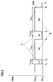
- FIG. 2 shows the optical data signal ODS provided for the optical transmission of data D in the first or second data stream DS1, DS2 with the aid of a diagram.
- the diagram has a horizontal and a vertical axis T, OSA, the time T or the point in time of the start and end of the transmission of data D by the horizontal axis and the amplitude OSA of the optical data signal ODS or the optical data D to be transmitted is displayed.
- the optical data signal ODS for example the first data stream DS1, has data-related time periods T Data and data- free time periods T NoData , with the data-related time periods T Data the optical data D to be transmitted and the data-free time periods T NoData the gaps L between the individual optical data D. represent.
- a first and a second gap L1, L2 and first and second data D1, D2 are shown in FIG. 2 to explain the method according to the invention, the amplitude OSA or the signal strength of the optical data signal ODS not exceeding a maximum signal amplitude value SA max and one does not fall below the minimum signal amplitude value SA Min .
- a gap L of the optical data signal ODS is realized by an optical data signal ODS having a minimum signal amplitude value SA Min and currently transmitted data D by means of an optical data signal ODS having a maximum signal amplitude value SA max .
- a first to fifth point in time t 1 -t 5 are shown in FIG. 2, at which the amplitude OSA of the optical data signal ODS changes the signal amplitude value SA min , SA max .
- the amplitude OSA of the optical data signal ODS assumes the minimum signal amplitude value SA min , which at the same time represents the beginning of a data-free period T NoData or the first gap L1.
- the time end of the first gap L1 has been reached and the first optical data D1 are transmitted, ie the amplitude OSA of the optical data signal ODS assumes the maximum signal amplitude value SA Max .
- the amplitude OSA of the optical data signal ODS is reset to the minimum signal amplitude value SA Min , ie a second gap L2 in the first or second data stream DS1, DS2 arises.
- second optical data D2 are transmitted, ie the amplitude OSA of the optical data signal ODS assumes the maximum signal amplitude value SA max .
- the amplitude OSA of the optical data signal ODS in turn remains unchanged for the duration of the data period T Data and finally assumes the minimum signal amplitude value SA min again at the fifth point in time t 5 after the end of the data period T Data or after the transmission of the second optical data D2 , ie a further gap L2 follows the second optical data D2.
- optical data signal ODS is only partially shown as an example in FIG. 2, that is to say, to measure the signal quality of an optical data signal with the aid of the method according to the invention, a large number of such optical data D and gaps L are required, which in their entirety constitute the continuous first and second data stream Represent DS1, DS2.
- additional gaps L can also be inserted into the first or second data stream, wherein the time interval between the inserted gaps L can always have the same time length.
- the data-free period T NoData between successive data D1, D2 should be significantly less than one millisecond, ie in the microsecond range.
- FIG 3 is a block diagram of an optical measuring system OMS to determine the signal quality, especially the signal-to-noise ratio snr, the first optical data stream DS1 is shown schematically, with the example in FIG Figure 1 shown optical transmission link between the first optical transmission device OTE1 and the optical one Network node ONK with regard to your transmission quality is monitored.
- a first optical coupling element OKE1 at any measuring point in the first optical Fiber OF1 integrated, with the help of which part of the first optical, transmitted in the first transmission direction TD1 Data stream DS1 'from the first optical data stream DS1 can be coupled out.
- the first optical coupling element OKE is connected to the via a first optical measuring fiber OMF1 optical measuring system OMS connected.
- a second optical coupling element OKE2 at the same measuring point integrated in the second optical fiber OF2, with the help of which part of the second optical, in the second transmission direction TD2 transmitted data stream DS2 'from the second optical Data stream DS2 can be coupled out.
- the second optical Coupling element OKE is over a second optical measuring fiber OMF2 connected to the OMS optical measuring system.
- the optical measuring system OMS has a converter unit WE, a signal strength measuring unit SSME, a storage unit SE, a control unit MC and a display unit AE on.
- the first and second optical measuring fibers are OMF1 / OMF2 led to the converter unit WE, which with the signal strength measuring unit SSME is connected.
- the control unit MC with the signal strength measuring unit SSME, with the converter unit WE and with connected to the memory unit SE
- the display unit additionally AE to represent the signal-to-noise ratio snr is connected to the control unit MC. Furthermore there is a connection between the signal strength measuring unit SSME and the storage unit SE.
- the method according to the invention for measuring the signal quality of an optical data signal DS1 / DS2 is explained in more detail below, for example on the basis of the first optical data stream DS1, the determination of the signal quality of the second optical data stream DS2 being able to be carried out analogously to this.
- part of the first optical data stream DS1 ' is separated from the first optical data stream DS1 and transmitted via the first optical measuring fiber OMF1 to the optical measuring system OMS or the converter unit WE.
- the converter unit WE the divided, first optical data stream DS1 'is converted into a first electrical data stream ds1' and transmitted to the signal strength measuring unit SSME and to the control unit MC.
- the first electrical data stream ds1 ′ is monitored in the control unit MC with regard to occurring, data-free time segments T NoData or gaps L. If a gap L occurs, a measurement of the signal strength of the noise signal or the noise of the transmission link is initiated directly with the aid of control commands sb transmitted to the signal strength measuring unit SSME, ie the noise signal strength sr is determined in the signal strength measuring unit SSME. The measured noise signal strength sr is then temporarily stored in the memory unit SE.
- the signal strength measurement unit SSME cyclically determines the signal strength of the first electrical data signal ds1 'when data D is currently being transmitted, that is to say in the data sections T Data , and the currently measured value of the data signal strength sd is temporarily stored in the memory unit SE.
- the in the memory unit SE temporarily stored noise signal strength sr and the data signal strength sd from the control unit MC read out from the memory unit SE.
- the signal-to-noise ratio snr of the current transmitted first optical data stream DS1 determined and displayed using the display unit AE, the display of the signal-to-noise ratio snr both acoustically and can be done visually.
- the length of the data-free time segments T NoData and the length of the data-related time segments T Data are determined and related in the control unit MC.
- the value resulting from the ratio of data-free to data-containing time segments T NoData , T Data is a measure, for example, of the signal distortions sv in the optical data signal ODS caused by the first optical fiber OF1 or the first optical transmission device OTE1 and can be used to assess the transmission quality of the optical transmission path can be made available.
- the value for the signal distortion sv in the optical data signal ODS determined in the control unit MC is displayed with the aid of the display unit AE.
- the frequency of the occurrence of gaps L within the first electrical data stream ds1 ' is determined by the control unit MC and displayed to the optical transmission device OTE1.
- a value for the frequency of the occurrence of gaps L is determined in the control unit MC and an electrical gap frequency signal lhs representing this value is transmitted to the converter unit WE.
- the electrical gap frequency signal lhs is converted into an optical gap frequency signal lhs' and transmitted to the second optical coupler unit OKE2 via the second optical measuring fiber OMF2.
- the optical gap frequency signal lhs' is coupled into the second optical data stream DS2 and transmitted to the first optical transmission device OTE1.
- the first optical transmission device OTE1 can insert additional data-free time segments T NoData for more precise measurement of the signal quality in the first optical data stream DS1, the additional ones inserted data-free time segments T NoData, for example, have the same length and can be inserted at a predetermined time interval.
- the described Repeated measurements of the signal strengths and from the calculated signal-to-noise ratio values becomes the mean educated. This must ensure a minimum measuring accuracy if the gap frequency is too low within of the first optical data stream DS1 to be transmitted additional gaps L in the first optical data stream DS1 be inserted.
- short test signals or test signal patterns can be inserted into the data-free time segments T NoData of the optical data signal ODS with the aid of the optical measuring system OMS, with the aid of which, for example, the reaction of the optical transmission system OTS or the optical transmission path with regard to nonlinear effects can be specifically examined .
- the method according to the invention is by no means used limited to WDM transmission systems, but can definitely for the implementation of any optical transmission links be used.
Abstract
Description
- Figur 1
- zeigt in einem Blockschaltbild beispielhaft den schematischen Aufbau eines optischen Übertragungssystems,
- Figur 2
- zeigt in einem Diagramm eine bei der optischen Übertragung von Daten entstehende, optische Signalstruktur, und
- Figur 3
- zeigt in einem Blockschaltbild ein optisches Meßsystem zur erfindungsgemäßen Bestimmung der Signalqualität eines optischen Datensignals.
Claims (6)
- Verfahren zum Messen der Signalqualität eines optischen Datensignals (ODS), das datenfreie Zeitabschnitte (TNoData) aufweist,
dadurch gekennzeichnet,daß die Signalstärke des übertragenen, optischen Datensignals (sd) gemessen wird,daß in den datenfreien Zeitabschnitten (TNoData) die Signalstärke des Rauschsignals (sr) gemessen wird unddaß anhand der gemessenen Signalstärken (sd,sr) der Signal-Rausch-Abstand (snr) als ein Kriterium für die Signalqualität des optischen Datensignals (ODS) bestimmt wird. - Verfahren nach Anspruch 1,
dadurch gekennzeichnet,daß gezielt zusätzliche datenfreie Zeitabschnitte (TNoData) in das optische Datensignal (ODS) zur Messung der Signalqualität eingefügt werden. - Verfahren nach Anspruch 1 oder 2,
dadurch gekennzeichnet,daß die gezielt zusätzlich eingefügten, datenfreien Zeitabschnitte (TNoData) dieselbe Länge aufweisen und in das optische Datensignal (ODS) in einem vorgegeben zeitlichen Abstand eingefügt werden. - Verfahren nach einem der Ansprüche 1 bis 3,
dadurch gekennzeichnet,daß aus dem Verhältnis der Längen der datenfreien Zeitabschnitte (TNoData) und der Datenübertragungszeitabschnitte (TData) ein Maß für die durch die optische Faser (OF1-OF4) bzw. optische Übertragungseinrichtungen (OTE1, OTE2, ONK) hervorgerufene Signalverzerrung des optischen Datensignals (ODS) bestimmt wird. - Verfahren nach einem der Ansprüche 1 bis 4,
dadurch gekennzeichnet,daß in die datenfreien Zeitabschnitte (TNoData) des optischen Datensignals (ODS) teilweise optische Testsignale eingefügt werden. - Verfahren nach einem der Ansprüche 1 bis 5,
dadurch gekennzeichnet,daß das Messen der Signalqualität des optischen Datensignals (ODS) bei aktuell bestehender, optischer Datenübertragung durchgeführt wird.
Applications Claiming Priority (2)
| Application Number | Priority Date | Filing Date | Title |
|---|---|---|---|
| DE19928940 | 1999-06-24 | ||
| DE19928940A DE19928940A1 (de) | 1999-06-24 | 1999-06-24 | Verfahren zum Messen der Signalqualität eines optischen Datensignals |
Publications (3)
| Publication Number | Publication Date |
|---|---|
| EP1063793A2 true EP1063793A2 (de) | 2000-12-27 |
| EP1063793A3 EP1063793A3 (de) | 2003-09-17 |
| EP1063793B1 EP1063793B1 (de) | 2008-12-17 |
Family
ID=7912378
Family Applications (1)
| Application Number | Title | Priority Date | Filing Date |
|---|---|---|---|
| EP00111520A Expired - Lifetime EP1063793B1 (de) | 1999-06-24 | 2000-05-29 | Verfahren zum Messen der Signalqualität eines optischen Datensignals |
Country Status (3)
| Country | Link |
|---|---|
| US (1) | US6748169B1 (de) |
| EP (1) | EP1063793B1 (de) |
| DE (2) | DE19928940A1 (de) |
Families Citing this family (8)
| Publication number | Priority date | Publication date | Assignee | Title |
|---|---|---|---|---|
| DE10111497B4 (de) * | 2001-03-09 | 2007-01-11 | Siemens Ag | Verfahren zur Ermittlung der Signalqualität bei optischen Übertragungssystemen |
| DE202004021208U1 (de) | 2003-10-15 | 2007-04-12 | Exfo Electro Optical Eng Inc | Vorrichtung zum Testen optischer Netzwerke |
| JP2006253950A (ja) * | 2005-03-09 | 2006-09-21 | Fujitsu Ltd | デバイスの特性劣化判定方法及び装置 |
| RU2518182C2 (ru) | 2009-08-31 | 2014-06-10 | Хуавэй Текнолоджиз Ко., Лтд. | Способ и устройство обнаружения внутриполосного оптического отношения сигнал-шум |
| US9847833B2 (en) * | 2014-06-12 | 2017-12-19 | Acacia Communications, Inc. | Optical signal-to-noise ratio (OSNR) monitoring and measurement in optical communications sytems |
| US9831948B2 (en) | 2015-09-22 | 2017-11-28 | Exfo Inc. | Optical power measurement in a passive optical network |
| US10270554B2 (en) | 2015-09-22 | 2019-04-23 | Exfo Inc. | Optical power measurement in a passive optical network |
| US10979141B1 (en) * | 2019-10-11 | 2021-04-13 | Nokia Technologies Oy | Optical network unit compliance detection |
Citations (3)
| Publication number | Priority date | Publication date | Assignee | Title |
|---|---|---|---|---|
| EP0714182A2 (de) * | 1994-11-25 | 1996-05-29 | PIRELLI CAVI S.p.A. | Telekommunikationssystem und Verfahren zur Wellenlängenmultiplexübertragung mit geregelten Trennen von abgehenden Kanälen und zur Bestimmung des Signal-Rauschverhältnis |
| DE19730294C1 (de) * | 1997-07-15 | 1998-10-15 | Deutsche Telekom Ag | Verfahren zur Übertragung von Signalisierungs- und Steuerinformationen für Wellenlängenmultiplex-Netze zur optischen, fasergebundenen Informationsübertragung |
| WO1998054862A1 (en) * | 1997-05-29 | 1998-12-03 | Ciena Corporation | Signal-to-noise monitoring in wdm optical communication systems |
Family Cites Families (4)
| Publication number | Priority date | Publication date | Assignee | Title |
|---|---|---|---|---|
| JP3373332B2 (ja) * | 1995-05-26 | 2003-02-04 | Kddi株式会社 | プリエンファシス方式光波長多重通信方法および装置 |
| US6285481B1 (en) * | 1997-09-05 | 2001-09-04 | Trex Communications Corporation | Free-space laser communications error control system |
| KR100292334B1 (ko) * | 1997-12-30 | 2001-07-12 | 서평원 | 더블유디엠시스템에서채널감시장치및방법 |
| KR100312224B1 (ko) * | 1998-07-02 | 2001-12-20 | 윤종용 | 파장 분할 다중 광 전송장치에서 광 신호 대 잡음비 측정장치 |
-
1999
- 1999-06-24 DE DE19928940A patent/DE19928940A1/de not_active Withdrawn
-
2000
- 2000-05-29 DE DE50015488T patent/DE50015488D1/de not_active Expired - Lifetime
- 2000-05-29 EP EP00111520A patent/EP1063793B1/de not_active Expired - Lifetime
- 2000-06-26 US US09/603,882 patent/US6748169B1/en not_active Expired - Lifetime
Patent Citations (3)
| Publication number | Priority date | Publication date | Assignee | Title |
|---|---|---|---|---|
| EP0714182A2 (de) * | 1994-11-25 | 1996-05-29 | PIRELLI CAVI S.p.A. | Telekommunikationssystem und Verfahren zur Wellenlängenmultiplexübertragung mit geregelten Trennen von abgehenden Kanälen und zur Bestimmung des Signal-Rauschverhältnis |
| WO1998054862A1 (en) * | 1997-05-29 | 1998-12-03 | Ciena Corporation | Signal-to-noise monitoring in wdm optical communication systems |
| DE19730294C1 (de) * | 1997-07-15 | 1998-10-15 | Deutsche Telekom Ag | Verfahren zur Übertragung von Signalisierungs- und Steuerinformationen für Wellenlängenmultiplex-Netze zur optischen, fasergebundenen Informationsübertragung |
Also Published As
| Publication number | Publication date |
|---|---|
| DE19928940A1 (de) | 2001-01-11 |
| EP1063793A3 (de) | 2003-09-17 |
| US6748169B1 (en) | 2004-06-08 |
| EP1063793B1 (de) | 2008-12-17 |
| DE50015488D1 (de) | 2009-01-29 |
Similar Documents
| Publication | Publication Date | Title |
|---|---|---|
| DE69736856T2 (de) | Überwachung von nichtlinearen Effekten in einem optischen Übertragungssystem | |
| DE19917751C2 (de) | Verfahren und Überwachungsvorrichtung zur Überwachung der Qualität der Datenübertragung über analoge Leitungen | |
| DE69530276T2 (de) | Pulsbasiertes Übersprechmessgerät mit Steckverbinderübersprechkompensation | |
| DE60024952T2 (de) | Vorrichtung und Verfahren zur Fehlerlokalisierung in einer Übertragungsstrecke | |
| DE3821772B4 (de) | Optische Zweiwege-Signalübertragungsvorrichtung mit einer Einrichtung zur Fehlerlokalisierung | |
| DE60226190T2 (de) | Verfahren und Vorrichtung zur Messung und Bestimmung des optischen Signal-Rauschverhältnis in optischen Netzwerken | |
| DE69837503T2 (de) | Vorrichtung und Verfahren zur Prüfung von optischen Einrichtungen | |
| DE69633842T2 (de) | Phasensynchronisationssystem | |
| EP2637361B1 (de) | Verfahren zur Bestimmung der Topologie eines seriellen asynchronen Datenbusses | |
| DE3115200C2 (de) | ||
| EP0213063A1 (de) | Schaltungsanordnung zur Prüfung eines passiven Busnetzsystems (CSMA/CD-Zugriffsverfahren) | |
| EP1796295A1 (de) | Verfahren zur Detektion und Ortung von Störungen auf einer optischen Übertragungsstrecke und optisches Übertragungssystem | |
| EP1063793B1 (de) | Verfahren zum Messen der Signalqualität eines optischen Datensignals | |
| DE69823609T2 (de) | Überwachung der optischen Signalleistung mit einem Signaturbitmuster in WDM Systemen | |
| DE102007015628B4 (de) | Verfahren und Einrichtung zur Überwachung einer Datenübertragungsstrecke, insbesondere einer optischen bidirektionalen Datenübertragungsstrecke | |
| DE19827638A1 (de) | Methode zur Messung von Störungseffekten auf Glasfaserübertragungsstrecken sowie Übertragungssystem | |
| DE102005016522A1 (de) | Diagnoseverfahren und Diagnosechip zur Bandbreitenbestimmung optischer Fasern | |
| DE19914793A1 (de) | Verfahren und Anordnung zur Messung der Signalqualität in einem optischen Übertragungssystem | |
| EP1224754B1 (de) | Verfahren und einrichtung zur kontinuierlichen überwachung einer optischen übertragungsstrecke | |
| EP0675351A2 (de) | Verfahren zur Bestimmung der Dispersionsnullstelle eines Lichtwellenleiters | |
| EP2260590A1 (de) | Dispersionsmessung von optischen fasern im laufenden betrieb | |
| EP0969613B1 (de) | Verfahren zur Überwachung der Signalqualität in optischen Netzen | |
| DE19930975A1 (de) | Verfahren zur Messung des individuellen Übersprechens in Wellenlängenmultiplex-Systemen und Wellenlängenmultiplex-System | |
| DE602004001196T2 (de) | Verfahren und Vorrichtung zur Datenübertragung für hybride isochrone/asynchrone Netzwerke | |
| DE69829799T2 (de) | Messung der Augenöffnung von optischen Signalen mittels optischen Abtasten |
Legal Events
| Date | Code | Title | Description |
|---|---|---|---|
| PUAI | Public reference made under article 153(3) epc to a published international application that has entered the european phase |
Free format text: ORIGINAL CODE: 0009012 |
|
| AK | Designated contracting states |
Kind code of ref document: A2 Designated state(s): AT BE CH CY DE DK ES FI FR GB GR IE IT LI LU MC NL PT SE |
|
| AX | Request for extension of the european patent |
Free format text: AL;LT;LV;MK;RO;SI |
|
| PUAL | Search report despatched |
Free format text: ORIGINAL CODE: 0009013 |
|
| AK | Designated contracting states |
Kind code of ref document: A3 Designated state(s): AT BE CH CY DE DK ES FI FR GB GR IE IT LI LU MC NL PT SE |
|
| AX | Request for extension of the european patent |
Extension state: AL LT LV MK RO SI |
|
| 17P | Request for examination filed |
Effective date: 20031006 |
|
| AKX | Designation fees paid |
Designated state(s): DE GB |
|
| RAP1 | Party data changed (applicant data changed or rights of an application transferred) |
Owner name: NOKIA SIEMENS NETWORKS GMBH & CO. KG |
|
| RAP3 | Party data changed (applicant data changed or rights of an application transferred) |
Owner name: NOKIA SIEMENS NETWORKS S.P.A. |
|
| RAP3 | Party data changed (applicant data changed or rights of an application transferred) |
Owner name: NOKIA SIEMENS NETWORKS GMBH & CO. KG |
|
| 17Q | First examination report despatched |
Effective date: 20071219 |
|
| GRAP | Despatch of communication of intention to grant a patent |
Free format text: ORIGINAL CODE: EPIDOSNIGR1 |
|
| GRAS | Grant fee paid |
Free format text: ORIGINAL CODE: EPIDOSNIGR3 |
|
| GRAA | (expected) grant |
Free format text: ORIGINAL CODE: 0009210 |
|
| AK | Designated contracting states |
Kind code of ref document: B1 Designated state(s): DE GB |
|
| REG | Reference to a national code |
Ref country code: GB Ref legal event code: FG4D Free format text: NOT ENGLISH |
|
| REF | Corresponds to: |
Ref document number: 50015488 Country of ref document: DE Date of ref document: 20090129 Kind code of ref document: P |
|
| PLBE | No opposition filed within time limit |
Free format text: ORIGINAL CODE: 0009261 |
|
| STAA | Information on the status of an ep patent application or granted ep patent |
Free format text: STATUS: NO OPPOSITION FILED WITHIN TIME LIMIT |
|
| 26N | No opposition filed |
Effective date: 20090918 |
|
| REG | Reference to a national code |
Ref country code: DE Ref legal event code: R082 Ref document number: 50015488 Country of ref document: DE Representative=s name: BOEHMERT & BOEHMERT, DE |
|
| REG | Reference to a national code |
Ref country code: DE Ref legal event code: R082 Ref document number: 50015488 Country of ref document: DE Representative=s name: BOEHMERT & BOEHMERT, DE Effective date: 20131106 Ref country code: DE Ref legal event code: R081 Ref document number: 50015488 Country of ref document: DE Owner name: XIEON NETWORKS S.A.R.L., LU Free format text: FORMER OWNER: NOKIA SIEMENS NETWORKS GMBH & CO. KG, 81541 MUENCHEN, DE Effective date: 20131106 Ref country code: DE Ref legal event code: R082 Ref document number: 50015488 Country of ref document: DE Representative=s name: BOEHMERT & BOEHMERT ANWALTSPARTNERSCHAFT MBB -, DE Effective date: 20131106 |
|
| REG | Reference to a national code |
Ref country code: GB Ref legal event code: 732E Free format text: REGISTERED BETWEEN 20131212 AND 20131218 |
|
| REG | Reference to a national code |
Ref country code: GB Ref legal event code: 732E Free format text: REGISTERED BETWEEN 20140130 AND 20140205 |
|
| REG | Reference to a national code |
Ref country code: DE Ref legal event code: R079 Ref document number: 50015488 Country of ref document: DE Free format text: PREVIOUS MAIN CLASS: H04B0010080000 Ipc: H04B0010070000 |
|
| REG | Reference to a national code |
Ref country code: DE Ref legal event code: R079 Ref document number: 50015488 Country of ref document: DE Free format text: PREVIOUS MAIN CLASS: H04B0010080000 Ipc: H04B0010070000 Effective date: 20141124 |
|
| PGFP | Annual fee paid to national office [announced via postgrant information from national office to epo] |
Ref country code: GB Payment date: 20160520 Year of fee payment: 17 |
|
| PGFP | Annual fee paid to national office [announced via postgrant information from national office to epo] |
Ref country code: DE Payment date: 20170523 Year of fee payment: 18 |
|
| GBPC | Gb: european patent ceased through non-payment of renewal fee |
Effective date: 20170529 |
|
| PG25 | Lapsed in a contracting state [announced via postgrant information from national office to epo] |
Ref country code: GB Free format text: LAPSE BECAUSE OF NON-PAYMENT OF DUE FEES Effective date: 20170529 |
|
| REG | Reference to a national code |
Ref country code: DE Ref legal event code: R119 Ref document number: 50015488 Country of ref document: DE |
|
| PG25 | Lapsed in a contracting state [announced via postgrant information from national office to epo] |
Ref country code: DE Free format text: LAPSE BECAUSE OF NON-PAYMENT OF DUE FEES Effective date: 20181201 |