EP1063793A2 - Optical data signal quality measurement method - Google Patents
Optical data signal quality measurement method Download PDFInfo
- Publication number
- EP1063793A2 EP1063793A2 EP00111520A EP00111520A EP1063793A2 EP 1063793 A2 EP1063793 A2 EP 1063793A2 EP 00111520 A EP00111520 A EP 00111520A EP 00111520 A EP00111520 A EP 00111520A EP 1063793 A2 EP1063793 A2 EP 1063793A2
- Authority
- EP
- European Patent Office
- Prior art keywords
- signal
- data
- optical
- ods
- optical data
- Prior art date
- Legal status (The legal status is an assumption and is not a legal conclusion. Google has not performed a legal analysis and makes no representation as to the accuracy of the status listed.)
- Granted
Links
Images


Classifications
-
- H—ELECTRICITY
- H04—ELECTRIC COMMUNICATION TECHNIQUE
- H04B—TRANSMISSION
- H04B10/00—Transmission systems employing electromagnetic waves other than radio-waves, e.g. infrared, visible or ultraviolet light, or employing corpuscular radiation, e.g. quantum communication
- H04B10/07—Arrangements for monitoring or testing transmission systems; Arrangements for fault measurement of transmission systems
- H04B10/075—Arrangements for monitoring or testing transmission systems; Arrangements for fault measurement of transmission systems using an in-service signal
- H04B10/077—Arrangements for monitoring or testing transmission systems; Arrangements for fault measurement of transmission systems using an in-service signal using a supervisory or additional signal
-
- H—ELECTRICITY
- H04—ELECTRIC COMMUNICATION TECHNIQUE
- H04B—TRANSMISSION
- H04B10/00—Transmission systems employing electromagnetic waves other than radio-waves, e.g. infrared, visible or ultraviolet light, or employing corpuscular radiation, e.g. quantum communication
- H04B10/07—Arrangements for monitoring or testing transmission systems; Arrangements for fault measurement of transmission systems
- H04B10/075—Arrangements for monitoring or testing transmission systems; Arrangements for fault measurement of transmission systems using an in-service signal
- H04B10/079—Arrangements for monitoring or testing transmission systems; Arrangements for fault measurement of transmission systems using an in-service signal using measurements of the data signal
- H04B10/0795—Performance monitoring; Measurement of transmission parameters
- H04B10/07955—Monitoring or measuring power
Definitions
- the invention relates to a method for measuring the signal quality an optical data signal, the data-free periods having.
- the transmission behavior of the optical transmission system or an optical transmission link to monitor can, the signal quality of the currently transmitted optical Data signal determined.
- optical signal parameters such as. the optical signal-to-noise ratio or the through optical transmission fibers or optical transmission devices caused signal distortion of the optical Data signal used.
- optical transmission systems implemented so far optical transmission links electronically closed, which is an opto-electronic conversion of the data signal for example in the transmission facilities.
- the determination of the signal quality of the optical data signal can thus in the transmission device based on a measurement performed on the opto-electrically converted data signal become.
- Optical Spectrum Analyzer a measuring method for determination the signal-to-noise ratio of an optical transmission channel known in which an optical with the help of a measuring instrument Measuring signal over the optical transmission path to be assessed is transmitted, the optical measurement signal in irregular intervals is interrupted.
- the optical measuring signal is arranged with the help of a measuring point additional measuring instrument the signal strength of the optical Measurement signal determined.
- the signal strength of the noise signal determined on the optical transmission link. Based The measured signal strengths can then be the signal-to-noise ratio the optical transmission path become.
- the object underlying the invention is that Measure the signal quality of an optical data signal improve.
- the task is based on a process according to the features of the preamble of claim 1 solved by the characteristic of the characteristic part.
- the essential aspect of the method according to the invention is to see that the signal strength of the transmitted, optical Data signal is measured. Furthermore, in the data-free Time segments the signal strength of the noise signal measured and based on the measured signal strengths the signal-to-noise ratio as a criterion for the signal quality of the optical data signal determined.
- Measuring the signal strength of the optical data signal will currently transmitted data signal with regard to its signal strength supervised.
- the optical data signal itself as a measurement signal for determining the signal-to-noise ratio of the Transmission channel used.
- optical data signal Data signal or interruptions occurring in the measurement signal the data transmission or the data-free periods the optical data signal to determine the signal strength of the noise signal can be used.
- optical partial signal determined without a measurement signal in addition to the data signal is to be provided. This makes the assessment of the signal quality an optical data signal by the signal-to-noise ratio criterion with currently existing data transmission enables.
- the targeted additional inserted data-free periods are targeted additional data-free periods into the optical data signal to measure the signal quality inserted - claim 2, wherein the targeted additional inserted data-free periods have the same length and in the optical data signal in a predetermined time Distance can be inserted - claim 3. Should that Optical data signal too few to determine the signal-to-noise ratio necessary, data-free periods have additional data-free according to the invention Periods inserted in the optical data signal to the required measurement accuracy and frequency for the determination to ensure the signal-to-noise ratio or to be explicit the signal quality of an optical "point-to-point" transmission link to be able to monitor.
- Another significant advantage of the method according to the invention can be seen in the fact that from the ratio of the lengths the data-free periods and the data transmission periods a measure of the through the optical fiber or optical Signal distortion caused by transmission equipment of the optical data signal is determined.
- a measure of the through the optical fiber or optical Signal distortion caused by transmission equipment of the optical data signal is determined.
- the resulting relationship at the location of the invention Measurement represents compared to the ratio in the transmitted original optical data signal Evaluation criterion for the through the optical fiber or optical Optical transmission devices Signal distortion.
- Figure 1 is a, for example, a first, second and third optical transmission device having OTE1-OTE3 optical transmission system OTS shown schematically, for example the first optical transmission device OTE1 a first input i1 and a first Output e1, the second optical transmission device OTE2 a second input i2 and a second output e2 as well the third optical transmission device OTE3 a third Has input i3 and a third output e3.
- OTS optical network node ONK provided, for example one first, second and third node inputs ik1, ik2, ik3 as well a first, second and third node output ek1, ek2, ek3 having.
- the first output e1 of the first optical transmission device OTE1 is OF1 via a first optical fiber with the first node input ik2 of the optical network node ONK connected and the first node output ek1 is using the second optical fiber OF2 to the second input i2 second optical transmission device OTE2 connected.
- the second output e2 is the second optical Transmission device OTE2 via the third optical fiber OF3 to the second node input ik2 of the optical network node ONK and the second node output ek2 of the optical Network node ONK via the fourth optical fiber OF4 to the first Input i1 of the first optical transmission device OTE1 connected.
- the first and second are optical Transmission device OTE1, OTE2 via the optical network node OKN connected for optical transmission of data D, where preferably a first data stream DS1 in a first transmission direction TD1 for optical transmission of data D from the first to the second optical transmission device OTE1, OTE2 and a second data stream DS2 in a second Transmission direction TD2 for the optical transmission of data D from the second to the first optical transmission device OTE2, OTE1 is provided.
- the third optical transmission device OTE3 for example, for feeding data D into the first and / or the second data stream DS1, DS2 via a first and second optical connecting fiber OV1, OV2 to the optical Network node ONK connected, the third node input ik3 or the third node output ek3 of the optical network node ONK with the third output e3 or with the third input i3 of the third optical transmission device OTE3 are connected.
- existing data D using the first and second connecting fibers OV1, OV2 and the optical network node ONK in the first or second transmission direction TD1, TD2 are fed into the first or second data stream DS1, DS2 or to the third optical transmission device
- Data D to be transmitted from the first or second data stream DS1, DS2 read out and to the third optical transmission device OTE3 can be transmitted.
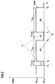
- FIG. 2 shows the optical data signal ODS provided for the optical transmission of data D in the first or second data stream DS1, DS2 with the aid of a diagram.
- the diagram has a horizontal and a vertical axis T, OSA, the time T or the point in time of the start and end of the transmission of data D by the horizontal axis and the amplitude OSA of the optical data signal ODS or the optical data D to be transmitted is displayed.
- the optical data signal ODS for example the first data stream DS1, has data-related time periods T Data and data- free time periods T NoData , with the data-related time periods T Data the optical data D to be transmitted and the data-free time periods T NoData the gaps L between the individual optical data D. represent.
- a first and a second gap L1, L2 and first and second data D1, D2 are shown in FIG. 2 to explain the method according to the invention, the amplitude OSA or the signal strength of the optical data signal ODS not exceeding a maximum signal amplitude value SA max and one does not fall below the minimum signal amplitude value SA Min .
- a gap L of the optical data signal ODS is realized by an optical data signal ODS having a minimum signal amplitude value SA Min and currently transmitted data D by means of an optical data signal ODS having a maximum signal amplitude value SA max .
- a first to fifth point in time t 1 -t 5 are shown in FIG. 2, at which the amplitude OSA of the optical data signal ODS changes the signal amplitude value SA min , SA max .
- the amplitude OSA of the optical data signal ODS assumes the minimum signal amplitude value SA min , which at the same time represents the beginning of a data-free period T NoData or the first gap L1.
- the time end of the first gap L1 has been reached and the first optical data D1 are transmitted, ie the amplitude OSA of the optical data signal ODS assumes the maximum signal amplitude value SA Max .
- the amplitude OSA of the optical data signal ODS is reset to the minimum signal amplitude value SA Min , ie a second gap L2 in the first or second data stream DS1, DS2 arises.
- second optical data D2 are transmitted, ie the amplitude OSA of the optical data signal ODS assumes the maximum signal amplitude value SA max .
- the amplitude OSA of the optical data signal ODS in turn remains unchanged for the duration of the data period T Data and finally assumes the minimum signal amplitude value SA min again at the fifth point in time t 5 after the end of the data period T Data or after the transmission of the second optical data D2 , ie a further gap L2 follows the second optical data D2.
- optical data signal ODS is only partially shown as an example in FIG. 2, that is to say, to measure the signal quality of an optical data signal with the aid of the method according to the invention, a large number of such optical data D and gaps L are required, which in their entirety constitute the continuous first and second data stream Represent DS1, DS2.
- additional gaps L can also be inserted into the first or second data stream, wherein the time interval between the inserted gaps L can always have the same time length.
- the data-free period T NoData between successive data D1, D2 should be significantly less than one millisecond, ie in the microsecond range.
- FIG 3 is a block diagram of an optical measuring system OMS to determine the signal quality, especially the signal-to-noise ratio snr, the first optical data stream DS1 is shown schematically, with the example in FIG Figure 1 shown optical transmission link between the first optical transmission device OTE1 and the optical one Network node ONK with regard to your transmission quality is monitored.
- a first optical coupling element OKE1 at any measuring point in the first optical Fiber OF1 integrated, with the help of which part of the first optical, transmitted in the first transmission direction TD1 Data stream DS1 'from the first optical data stream DS1 can be coupled out.
- the first optical coupling element OKE is connected to the via a first optical measuring fiber OMF1 optical measuring system OMS connected.
- a second optical coupling element OKE2 at the same measuring point integrated in the second optical fiber OF2, with the help of which part of the second optical, in the second transmission direction TD2 transmitted data stream DS2 'from the second optical Data stream DS2 can be coupled out.
- the second optical Coupling element OKE is over a second optical measuring fiber OMF2 connected to the OMS optical measuring system.
- the optical measuring system OMS has a converter unit WE, a signal strength measuring unit SSME, a storage unit SE, a control unit MC and a display unit AE on.
- the first and second optical measuring fibers are OMF1 / OMF2 led to the converter unit WE, which with the signal strength measuring unit SSME is connected.
- the control unit MC with the signal strength measuring unit SSME, with the converter unit WE and with connected to the memory unit SE
- the display unit additionally AE to represent the signal-to-noise ratio snr is connected to the control unit MC. Furthermore there is a connection between the signal strength measuring unit SSME and the storage unit SE.
- the method according to the invention for measuring the signal quality of an optical data signal DS1 / DS2 is explained in more detail below, for example on the basis of the first optical data stream DS1, the determination of the signal quality of the second optical data stream DS2 being able to be carried out analogously to this.
- part of the first optical data stream DS1 ' is separated from the first optical data stream DS1 and transmitted via the first optical measuring fiber OMF1 to the optical measuring system OMS or the converter unit WE.
- the converter unit WE the divided, first optical data stream DS1 'is converted into a first electrical data stream ds1' and transmitted to the signal strength measuring unit SSME and to the control unit MC.
- the first electrical data stream ds1 ′ is monitored in the control unit MC with regard to occurring, data-free time segments T NoData or gaps L. If a gap L occurs, a measurement of the signal strength of the noise signal or the noise of the transmission link is initiated directly with the aid of control commands sb transmitted to the signal strength measuring unit SSME, ie the noise signal strength sr is determined in the signal strength measuring unit SSME. The measured noise signal strength sr is then temporarily stored in the memory unit SE.
- the signal strength measurement unit SSME cyclically determines the signal strength of the first electrical data signal ds1 'when data D is currently being transmitted, that is to say in the data sections T Data , and the currently measured value of the data signal strength sd is temporarily stored in the memory unit SE.
- the in the memory unit SE temporarily stored noise signal strength sr and the data signal strength sd from the control unit MC read out from the memory unit SE.
- the signal-to-noise ratio snr of the current transmitted first optical data stream DS1 determined and displayed using the display unit AE, the display of the signal-to-noise ratio snr both acoustically and can be done visually.
- the length of the data-free time segments T NoData and the length of the data-related time segments T Data are determined and related in the control unit MC.
- the value resulting from the ratio of data-free to data-containing time segments T NoData , T Data is a measure, for example, of the signal distortions sv in the optical data signal ODS caused by the first optical fiber OF1 or the first optical transmission device OTE1 and can be used to assess the transmission quality of the optical transmission path can be made available.
- the value for the signal distortion sv in the optical data signal ODS determined in the control unit MC is displayed with the aid of the display unit AE.
- the frequency of the occurrence of gaps L within the first electrical data stream ds1 ' is determined by the control unit MC and displayed to the optical transmission device OTE1.
- a value for the frequency of the occurrence of gaps L is determined in the control unit MC and an electrical gap frequency signal lhs representing this value is transmitted to the converter unit WE.
- the electrical gap frequency signal lhs is converted into an optical gap frequency signal lhs' and transmitted to the second optical coupler unit OKE2 via the second optical measuring fiber OMF2.
- the optical gap frequency signal lhs' is coupled into the second optical data stream DS2 and transmitted to the first optical transmission device OTE1.
- the first optical transmission device OTE1 can insert additional data-free time segments T NoData for more precise measurement of the signal quality in the first optical data stream DS1, the additional ones inserted data-free time segments T NoData, for example, have the same length and can be inserted at a predetermined time interval.
- the described Repeated measurements of the signal strengths and from the calculated signal-to-noise ratio values becomes the mean educated. This must ensure a minimum measuring accuracy if the gap frequency is too low within of the first optical data stream DS1 to be transmitted additional gaps L in the first optical data stream DS1 be inserted.
- short test signals or test signal patterns can be inserted into the data-free time segments T NoData of the optical data signal ODS with the aid of the optical measuring system OMS, with the aid of which, for example, the reaction of the optical transmission system OTS or the optical transmission path with regard to nonlinear effects can be specifically examined .
- the method according to the invention is by no means used limited to WDM transmission systems, but can definitely for the implementation of any optical transmission links be used.
Abstract
Description
Die Erfindung betrifft ein Verfahren zum Messen der Signalqualität eines optischen Datensignals, das datenfreie Zeitabschnitte aufweist.The invention relates to a method for measuring the signal quality an optical data signal, the data-free periods having.
In bestehenden und zukünftigen optischen Übertragungssystemen, insbesondere in nach dem WDM-Prinzip (Wavelength Division Multiplexing) arbeitenden Übertragungssystemen, werden Daten in Form von Datenpaketen mit Hilfe eines optischen Datensignals übertragen, wobei die Datenpakete aus unterschiedlichen Signalarten bestehen können und speziell beim Einsatz der WDM-Technik den einzelnen Datenpaketen mehrere Übertragungkanäle zugeordnet werden. Derartige Signalarten können sich sowohl hinsichtlich des verwendeten Protokolls und/oder der benutzten Datenübertragungsraten unterscheiden. Als Beispiele hierfür sind unter anderem ATM (Asynchronous Transfer Mode), IP (Internet Protokoll) und Gigabit Ethernet zu nennen.In existing and future optical transmission systems, especially in accordance with the WDM principle (Wavelength Division Multiplexing) operating transmission systems, data in the form of data packets using an optical data signal transmitted, the data packets from different Signal types can exist and especially when used the WDM technology the individual data packets multiple transmission channels be assigned. Such types of signals can yourself with regard to the protocol used and / or differentiate the data transfer rates used. As examples this includes, among others, ATM (Asynchronous Transfer Mode), IP (Internet Protocol) and Gigabit Ethernet.
Um das Übertragungsverhalten des optischen Übertragungssysterns bzw. einer optischen Übertragungsstrecke überwachen zu können, wird die Signalqualität des aktuell übertragenen optischen Datensignals bestimmt. Zur Beurteilung der Signalqualität des optischen Datensignals werden optische Signalkenngrößen wie z.B. der optische Signal-Rausch-Abstand oder die durch optische Übertragungsfasern bzw. optische Übertragungseinrichtungen hervorgerufenen Signalverzerrungen des optischen Datensignals herangezogen.The transmission behavior of the optical transmission system or an optical transmission link to monitor can, the signal quality of the currently transmitted optical Data signal determined. To assess the signal quality of the optical data signal become optical signal parameters such as. the optical signal-to-noise ratio or the through optical transmission fibers or optical transmission devices caused signal distortion of the optical Data signal used.
In bislang realisierten optischen Übertragungssystemen werden optische Übertragungsstrecken elektronisch abgeschlossen, welches eine opto-elektronische Wandlung des Datensignals beispielsweise in den Übertragungseinrichtungen voraussetzt. In optical transmission systems implemented so far optical transmission links electronically closed, which is an opto-electronic conversion of the data signal for example in the transmission facilities.
Die Bestimmung der Signalqualität des optischen Datensignals kann somit in der Übertragungseinrichtung anhand einer Messung an dem opto-elektrisch gewandelten Datensignal durchgeführt werden. Mit zunehmenden Einsatz von rein optischen Übertragungssystemen bzw. Übertragungseinrichtungen besteht ein erheblicher Bedarf an Verfahren zum Messen der Signalqualität von optischen Datensignalen bei aktuell bestehender optischer Datenübertragung, d.h. ohne das eine vorhergehende opto-elektrische Wandlung des zu überwachenden Datensignals durchgeführt werden muß.The determination of the signal quality of the optical data signal can thus in the transmission device based on a measurement performed on the opto-electrically converted data signal become. With the increasing use of purely optical Transmission systems or transmission facilities exist a significant need for methods of measuring signal quality of optical data signals with currently existing optical Data transmission, i.e. without the previous one opto-electrical conversion of the data signal to be monitored must be carried out.
Desweiteren ist aus der Hewlett Packard Product Note 71452-2 "Optical Spectrum Analyzer" ein Meßverfahren zur Bestimmung des Signal-Rausch-Abstandes eines optischen Übertragungskanals bekannt, bei dem mit Hilfe eines Meßinstruments ein optisches Meßsignal über die zu beurteilende, optische Übertragungsstrecke übertragen wird, wobei das optische Meßsignal in unregelmäßigen Abständen unterbrochen wird. Beim Anliegen des optischen Meßsignals wird mit Hilfe eines am Meßpunkt angeordneten zusätzlichen Meßinstruments die Signalstarke des optischen Meßsignals bestimmt. Des weiteren wird nach dem Eintreten einer Unterbrechung des optischen Meßsignals, d.h. in dem signalfreien Zeitabschnitt, die Signalsstärke des Rauschsignals auf der optischen Übertragungsstrecke ermittelt. Anhand der gemessenen Signalsstärken kann anschließend der Signal-Rausch-Abstand der optischen Übertragungsstrecke bestimmt werden. Obwohl die Anwendung eines derartigen Verfahrens akzeptable Meßergebnisse liefert, ist es für die Messung des Signal-Rausch-Abstandes bei "live traffic", d.h. während der aktuellen Datenübertragung, nicht anwendbar, da ein zusätzliches optisches Hilfssignal bzw. Meßsignal erzeugt und über die optische Übertragungsstrecke bzw. das optische Übertragungssystem mitübertragen werden muß.Furthermore, from Hewlett Packard Product Note 71452-2 "Optical Spectrum Analyzer" a measuring method for determination the signal-to-noise ratio of an optical transmission channel known in which an optical with the help of a measuring instrument Measuring signal over the optical transmission path to be assessed is transmitted, the optical measurement signal in irregular intervals is interrupted. When the optical measuring signal is arranged with the help of a measuring point additional measuring instrument the signal strength of the optical Measurement signal determined. Furthermore, after entering an interruption of the optical measurement signal, i.e. in the signal-free period, the signal strength of the noise signal determined on the optical transmission link. Based The measured signal strengths can then be the signal-to-noise ratio the optical transmission path become. Although the application of such a procedure provides acceptable measurement results, it is for measurement the signal-to-noise ratio in "live traffic", i.e. while the current data transmission, not applicable, because an additional optical auxiliary signal or measurement signal generated and via the optical transmission path or the optical transmission system must also be transmitted.
Die der Erfindung zugrundeliegende Aufgabe besteht darin, das
Messen der Signalqualität eines optischen Datensignals zu
verbessern. Die Aufgabe wird ausgehend von einem Verfahren
gemäß den Merkmalen des Oberbegriffs des Patentanspruches 1
durch das Merkmal des kennzeichnenden Teils gelöst.The object underlying the invention is that
Measure the signal quality of an optical data signal
improve. The task is based on a process
according to the features of the preamble of
Der wesentliche Aspekt des erfindungsgemäßen Verfahrens ist darin zu sehen, daß die Signalstärke des übertragenen, optischen Datensignals gemessen wird. Desweiteren wird in den datenfreien Zeitabschnitten die Signalstärke des Rauschsignals gemessen und anhand der gemessenen Signalstärken der Signal-Rausch-Abstand als ein Kriterium für die Signalqualität des optischen Datensignals bestimmt. Durch das erfindungsgemäße Messen der Signalstärke des optischen Datensignals wird das aktuell übertragene Datensignal hinsichtlich seiner Signalstärke überwacht. Somit wird das optische Datensignal an sich als Meßsignal zur Bestimmung des Signal-Rausch-Abstandes des Übertragungskanals benutzt. Desweiteren wird auf vorteilhafte Weise die Signalstärke des Rauschsignals in den datenfreien Zeitabschnitten gemessen. Dadurch können die ohnehin im optischen Datensignal bzw. im Meßsignal auftretenden Unterbrechungen der Datenübertragung bzw. die datenfreien Zeitabschnitte des optischen Datensignals zur Bestimmung der Signalstärke des Rauschsignals benutzt werden. Somit kann an beliebigen Stellen einer optischen Übertragungsstrecke der Signal-Rausch-Abstand eines anhand eines aus dem optischen Datensignal ausgekoppelten, optischen Teilsignals bestimmt werden, ohne das ein Meßsignal zusätzlich zum Datensignal vorzusehen ist. Hierdurch wird die Beurteilung der Signalqualität eines optischen Datensignals durch das Signal-Rausch-Abstands-Kriterum bei aktuell bestehender Datenübertragung ermöglicht.The essential aspect of the method according to the invention is to see that the signal strength of the transmitted, optical Data signal is measured. Furthermore, in the data-free Time segments the signal strength of the noise signal measured and based on the measured signal strengths the signal-to-noise ratio as a criterion for the signal quality of the optical data signal determined. By the invention Measuring the signal strength of the optical data signal will currently transmitted data signal with regard to its signal strength supervised. Thus the optical data signal itself as a measurement signal for determining the signal-to-noise ratio of the Transmission channel used. Furthermore, advantageous Way the signal strength of the noise signal in the data-free Periods measured. This allows the optical anyway Data signal or interruptions occurring in the measurement signal the data transmission or the data-free periods the optical data signal to determine the signal strength of the noise signal can be used. Thus, on anywhere in an optical transmission path Signal-to-noise ratio based on one from the optical Data signal decoupled, optical partial signal determined without a measurement signal in addition to the data signal is to be provided. This makes the assessment of the signal quality an optical data signal by the signal-to-noise ratio criterion with currently existing data transmission enables.
Gemäß einer weiteren Ausgestaltung des erfindungsgemäßen Verfahrens werden gezielt zusätzliche datenfreie Zeitabschnitte in das optische Datensignal zur Messung der Signalqualität eingefügt - Anspruch 2, wobei die gezielt zusätzlich eingefügten datenfreien Zeitabschnitte dieselbe Länge aufweisen und in das optische Datensignal in einem vorgegeben zeitlichen Abstand eingefügt werden können - Anspruch 3. Sollte das optische Datensignal zu wenige, für die Bestimmung des Signal-Rausch-Abstandes notwendige, datenfreie Zeitabschnitte aufweisen, werden erfindungsgemäß zusätzliche datenfreie Zeitabschnitte in das optische Datensignal eingefügt, um die geforderte Meßgenauigkeit und -häufigkeit für die Bestimmung des Signal-Rausch-Abstandes zu gewährleisten bzw. um explizit die Signalqualität einer optischen "Punkt-zu-Punkt"-Übertragungsstrecke überwachen zu können.According to a further embodiment of the method according to the invention are targeted additional data-free periods into the optical data signal to measure the signal quality inserted - claim 2, wherein the targeted additional inserted data-free periods have the same length and in the optical data signal in a predetermined time Distance can be inserted - claim 3. Should that Optical data signal too few to determine the signal-to-noise ratio necessary, data-free periods have additional data-free according to the invention Periods inserted in the optical data signal to the required measurement accuracy and frequency for the determination to ensure the signal-to-noise ratio or to be explicit the signal quality of an optical "point-to-point" transmission link to be able to monitor.
Ein weiterer wesentlicher Vorteil des erfindungsgemäßen Verfahrens ist darin zu sehen, daß aus dem Verhältnis der Längen der datenfreien Zeitabschnitte und der Datenübertragungszeitabschnitte ein Maß für die durch die optische Faser bzw. optische Übertragungseinrichtungen hervorgerufene Signalverzerrung des optischen Datensignals bestimmt wird. Zusätzlich zum Messen der Signalstärke des Rauschsignals und des optischen Datensignals werden auf vorteilhafte Weise die zeitlichen Längen der datenfreien Zeitabschnitte und der Datenübertragungszeitabschnitte, d.h. die Zeitabschnitte in denen Daten explizit übertragen werden, ermittelt und zueinander ins Verhältnis gesetzt. Das sich ergebende Verhältnis am Ort der erfindungsgemäßen Messung stellt im Vergleich zum Verhältnis beim ausgesandten ursprünglichen optischen Datensignal ein Bewertungskriterium für die durch die optische Faser bzw. optische Übertragungseinrichtungen hervorgerufenen optischen Signalverzerrungen dar.Another significant advantage of the method according to the invention can be seen in the fact that from the ratio of the lengths the data-free periods and the data transmission periods a measure of the through the optical fiber or optical Signal distortion caused by transmission equipment of the optical data signal is determined. In addition to Measuring the signal strength of the noise signal and the optical Data signals are the temporal in an advantageous manner Lengths of the data-free periods and the data transmission periods, i.e. the periods in which data are explicitly transferred, determined and related to each other set. The resulting relationship at the location of the invention Measurement represents compared to the ratio in the transmitted original optical data signal Evaluation criterion for the through the optical fiber or optical Optical transmission devices Signal distortion.
Weitere vorteilhafte Ausgestaltungen des erfindungsgemäßen Verfahrens sind den weiteren Ansprüchen zu entnehmen.Further advantageous embodiments of the invention The method can be found in the further claims.
Die Erfindung soll im folgenden anhand von einem Blockschaltbild und einem Diagramm näher erläutert werden.
Figur 1- zeigt in einem Blockschaltbild beispielhaft den schematischen Aufbau eines optischen Übertragungssystems,
- Figur 2
- zeigt in einem Diagramm eine bei der optischen Übertragung von Daten entstehende, optische Signalstruktur, und
- Figur 3
- zeigt in einem Blockschaltbild ein optisches Meßsystem zur erfindungsgemäßen Bestimmung der Signalqualität eines optischen Datensignals.
- Figure 1
- FIG. 2 shows an example of the schematic structure of an optical transmission system in a block diagram, FIG.
- Figure 2
- shows in a diagram an optical signal structure which arises during the optical transmission of data, and
- Figure 3
- shows in a block diagram an optical measuring system for determining the signal quality of an optical data signal according to the invention.
In Figur 1 ist ein beispielsweise eine erste, zweite und dritte, optische Übertragungseinrichtung OTE1-OTE3 aufweisendes, optisches Übertragungssystem OTS schematisch dargestellt, wobei beispielsweise die erste optische Übertragungseinrichtung OTE1 einen ersten Eingang i1 und einen ersten Ausgang e1, die zweite optische Übertragungseinrichtung OTE2 einen zweiten Eingang i2 und einen zweiten Ausgang e2 sowie die dritte optische Übertragungseinrichtung OTE3 einen dritten Eingang i3 und einen dritten Ausgang e3 aufweist. Des weiteren ist in der optischen Übertragungseinrichtung OTS ein optischer Netzknoten ONK vorgesehen, der beispielsweise einen ersten, zweiten und dritten Knoteneingang ik1,ik2,ik3 sowie einen ersten, zweiten und dritten Knotenausgang ek1,ek2,ek3 aufweist. Der erste Ausgang e1 der ersten optischen Übertragungseinrichtung OTE1 ist über eine erste optische Faser OF1 mit dem ersten Knoteneingang ik2 des optischen Netzknotens ONK verbunden und der erste Knotenausgang ek1 ist mit Hilfe der zweiten optischen Faser OF2 an den zweiten Eingang i2 der zweiten optischen Übertragungseinrichtung OTE2 angeschlossen. Analog dazu ist der zweite Ausgang e2 der zweiten optischen Übertragungseinrichtung OTE2 über die dritte optische Faser OF3 an den zweiten Knoteneingang ik2 des optischen Netzknotens ONK sowie der zweite Knotenausgang ek2 des optischen Netzknotens ONK über die vierte optische Faser OF4 an den ersten Eingang i1 der ersten optischen Übertragungseinrichtung OTE1 angeschlossen. Somit sind die erste und zweite optische Übertragungseinrichtung OTE1,OTE2 über den optischen Netzknoten OKN zur optischen Übertragung von Daten D verbunden, wobei bevorzugt ein erster Datenstrom DS1 in einer ersten Übertragungsrichtung TD1 zur optischen Übertragung von Daten D von der ersten zur zweiten optischen Übertragungseinrichtung OTE1,OTE2 und ein zweiter Datenstrom DS2 in einer zweiten Übertragungsrichtung TD2 zur optischen Übertragung von Daten D von der zweiten zur ersten optischen Übertragungseinrichtung OTE2,OTE1 vorgesehen ist.In Figure 1 is a, for example, a first, second and third optical transmission device having OTE1-OTE3 optical transmission system OTS shown schematically, for example the first optical transmission device OTE1 a first input i1 and a first Output e1, the second optical transmission device OTE2 a second input i2 and a second output e2 as well the third optical transmission device OTE3 a third Has input i3 and a third output e3. Of another is in the optical transmission device OTS optical network node ONK provided, for example one first, second and third node inputs ik1, ik2, ik3 as well a first, second and third node output ek1, ek2, ek3 having. The first output e1 of the first optical transmission device OTE1 is OF1 via a first optical fiber with the first node input ik2 of the optical network node ONK connected and the first node output ek1 is using the second optical fiber OF2 to the second input i2 second optical transmission device OTE2 connected. Analogously, the second output e2 is the second optical Transmission device OTE2 via the third optical fiber OF3 to the second node input ik2 of the optical network node ONK and the second node output ek2 of the optical Network node ONK via the fourth optical fiber OF4 to the first Input i1 of the first optical transmission device OTE1 connected. Thus, the first and second are optical Transmission device OTE1, OTE2 via the optical network node OKN connected for optical transmission of data D, where preferably a first data stream DS1 in a first transmission direction TD1 for optical transmission of data D from the first to the second optical transmission device OTE1, OTE2 and a second data stream DS2 in a second Transmission direction TD2 for the optical transmission of data D from the second to the first optical transmission device OTE2, OTE1 is provided.
Des weiteren ist die dritte optische Übertragungseinrichtung OTE3 beispielsweise zum Einspeisen von Daten D in den ersten und/oder den zweiten Datenstrom DS1,DS2 über eine erste und zweite optische Verbindungsfaser OV1,OV2 an den optischen Netzknoten ONK angeschlossen, wobei der dritte Knoteneingang ik3 bzw. der dritte Knotenausgang ek3 des optischen Netzknotens ONK mit dem dritten Ausgang e3 bzw. mit dem dritten Eingang i3 der dritten optischen Übertragungseinrichtung OTE3 verbunden sind. Somit können in der dritten optischen Übertragungsrichtung OTE3 vorhandene Daten D mit Hilfe der ersten und zweiten Verbindungsfasern OV1,OV2 und dem optischen Netzknoten ONK in erster oder zweiter Übertragungsrichtung TD1,TD2 in den ersten oder zweiten Datenstrom DS1,DS2 eingespeist oder an die dritte optische Übertragungseinrichtung OTE3 zu übermittelnde Daten D aus dem ersten oder zweiten Datenstrom DS1,DS2 ausgelesen sowie zur dritten optischen Übertragungseinrichtung OTE3 übertragen werden.Furthermore, the third optical transmission device OTE3, for example, for feeding data D into the first and / or the second data stream DS1, DS2 via a first and second optical connecting fiber OV1, OV2 to the optical Network node ONK connected, the third node input ik3 or the third node output ek3 of the optical network node ONK with the third output e3 or with the third input i3 of the third optical transmission device OTE3 are connected. Thus, in the third optical transmission direction OTE3 existing data D using the first and second connecting fibers OV1, OV2 and the optical network node ONK in the first or second transmission direction TD1, TD2 are fed into the first or second data stream DS1, DS2 or to the third optical transmission device Data D to be transmitted from the first or second data stream DS1, DS2 read out and to the third optical transmission device OTE3 can be transmitted.
In Figur 2 ist die zur optischen Übertragung von Daten D im ersten bzw. zweiten Datenstrom DS1,DS2 vorgesehene, optische Datensignal ODS mit Hilfe eines Diagramms dargestellt. Das Diagramm weist eine horizontale und eine vertikale Achse T, OSA auf, wobei durch die horizontale Achse die Zeit T bzw. der Zeitpunkt des Anfangs und des Endes der Übertragung von Daten D und durch die vertikale Achse OSA die Amplitude OSA des optischen Datensignals ODS bzw. der zu übertragenden, optischen Daten D angezeigt wird. Das optische Datensignal ODS, beispielsweise der erste Datenstrom DS1, weist datenbehaftete Zeitabschnitte TData und datenfreie Zeitabschnitte TNoData auf, wobei die datenbehafteten Zeitabschnitte TData die zu übertragenden optischen Daten D und die datenfreien Zeitabschnitte TNoData die Lücken L zwischen den einzelnen optischen Daten D darstellen. In Figur 2 sind beispielhaft eine erste und eine zweite Lücke L1,L2 und erste und zweite Daten D1,D2 zur Erläuterung des erfindungsgemäßen Verfahrens dargestellt, wobei die Amplitude OSA bzw. die Signalstärke des optischen Datensignals ODS einen maximalen Signalamplitudenwert SAmax nicht überschreitet und einen minimalen Signalamplitudenwert SAMin nicht unterschreitet. Somit wird eine Lücke L des optischen Datensignals ODS durch ein einen minimalen Signalamplitudenwert SAMin aufweisendes, optisches Datensignal ODS und aktuell übertragene Daten D mit Hilfe eines einen maximalen Signalamplitudenwert SAmax aufweisenden, optischen Datensignals ODS realisiert.FIG. 2 shows the optical data signal ODS provided for the optical transmission of data D in the first or second data stream DS1, DS2 with the aid of a diagram. The diagram has a horizontal and a vertical axis T, OSA, the time T or the point in time of the start and end of the transmission of data D by the horizontal axis and the amplitude OSA of the optical data signal ODS or the optical data D to be transmitted is displayed. The optical data signal ODS, for example the first data stream DS1, has data-related time periods T Data and data- free time periods T NoData , with the data-related time periods T Data the optical data D to be transmitted and the data-free time periods T NoData the gaps L between the individual optical data D. represent. A first and a second gap L1, L2 and first and second data D1, D2 are shown in FIG. 2 to explain the method according to the invention, the amplitude OSA or the signal strength of the optical data signal ODS not exceeding a maximum signal amplitude value SA max and one does not fall below the minimum signal amplitude value SA Min . Thus, a gap L of the optical data signal ODS is realized by an optical data signal ODS having a minimum signal amplitude value SA Min and currently transmitted data D by means of an optical data signal ODS having a maximum signal amplitude value SA max .
Des weiteren sind in Figur 2 ein erster bis fünfter Zeitpunkt t1-t5 beispielhaft dargestellt, an denen jeweils die Amplitude OSA des optischen Datensignals ODS den Signalamplitudenwert SAmin, SAmax wechselt. Zum ersten Zeitpunkt t1 nimmt die Amplitude OSA des optischen Datensignals ODS den minimalen Signalamplitudenwert SAmin an, was zugleich den Beginn eines datenfreien Zeitabschnitts TNoData bzw. der ersten Lücke L1 darstellt. Nach Verstreichen des datenfreien Zeitabschnitts TNoData bzw. zum zweiten Zeitpunkt t2 ist das zeitliche Ende der erste Lücke L1 erreicht und die ersten optischen Daten D1 werden übertragen, d.h. die Amplitude OSA des optischen Datensignals ODS nimmt den maximalen Signalamplitudenwert SAMax an. Nach optischer Übertragung der ersten optischen Daten D1, welches der Dauer des datenbehafteten Zeitabschnitts TData entspricht, wird zum dritten Zeitpunkt t3 die Amplitude OSA des optischen Datensignals ODS auf den minimalen Signalamplitudenwert SAMin zurückgesetzt, d.h. eine zweite Lücke L2 in den ersten bzw. zweiten Datenstrom DS1, DS2 entsteht.In addition, a first to fifth point in time t 1 -t 5 are shown in FIG. 2, at which the amplitude OSA of the optical data signal ODS changes the signal amplitude value SA min , SA max . At the first point in time t 1 , the amplitude OSA of the optical data signal ODS assumes the minimum signal amplitude value SA min , which at the same time represents the beginning of a data-free period T NoData or the first gap L1. After the data-free time period T NoData has elapsed or at the second time t 2 , the time end of the first gap L1 has been reached and the first optical data D1 are transmitted, ie the amplitude OSA of the optical data signal ODS assumes the maximum signal amplitude value SA Max . After optical transmission of the first optical data D1, which corresponds to the duration of the data period T Data , at the third time t 3 the amplitude OSA of the optical data signal ODS is reset to the minimum signal amplitude value SA Min , ie a second gap L2 in the first or second data stream DS1, DS2 arises.
Zum vierten Zeitpunkt t4 bzw. nach Ablauf des datenfreien Zeitabschnitts TNoData werden zweite optische Daten D2 übertragen, d.h. die Amplitude OSA des optischen Datensignals ODS nimmt den maximalen Signalamplitudenwert SAmax an. Die Amplitude OSA des optischen Datensignals ODS bleibt wiederum für die Dauer des datenbehafteten Zeitabschnitts TData unverändert und nimmt schließlich nach Ablauf des datenbehafteten Zeitabschnitts TData bzw. nach der Übertragung der zweiten optischen Daten D2 zum fünften Zeitpunkt t5 den minimalen Signalamplitudenwert SAmin erneut an, d.h. eine weitere Lücke L2 schließt sich den zweiten optischen Daten D2 an.At the fourth time t 4 or after the end of the data-free period T NoData , second optical data D2 are transmitted, ie the amplitude OSA of the optical data signal ODS assumes the maximum signal amplitude value SA max . The amplitude OSA of the optical data signal ODS in turn remains unchanged for the duration of the data period T Data and finally assumes the minimum signal amplitude value SA min again at the fifth point in time t 5 after the end of the data period T Data or after the transmission of the second optical data D2 , ie a further gap L2 follows the second optical data D2.
Das zuvor beschriebene optische Datensignal ODS ist in Figur 2 beispielhaft nur ausschnittsweise dargestellt, d.h. zum Messen der Signalqualität eines optischen Datensignals mit Hilfe des erfindungsgemäßen Verfahrens werden eine Vielzahl derartiger optischer Daten D und Lücken L benötigt, die in Ihrer Gesamtheit den kontinuierlichen ersten und zweiten Datenstrom DS1,DS2 darstellen. Dabei können erfindungsgemäß auch zusätzliche Lücken L in den ersten bzw. zweiten Datenstrom eingefügt werden, wobei der zeitliche Abstand der eingefügten Lücken L jeweils immer dieselbe zeitliche Länge aufweisen kann. Jedoch sollte der datenfreie Zeitabschnitt TNoData zwischen aufeinanderfolgenden Daten D1,D2 deutlich kleiner als eine Millisekunde, d.h. im Mikrosekundenbereich, sein.The above-described optical data signal ODS is only partially shown as an example in FIG. 2, that is to say, to measure the signal quality of an optical data signal with the aid of the method according to the invention, a large number of such optical data D and gaps L are required, which in their entirety constitute the continuous first and second data stream Represent DS1, DS2. According to the invention, additional gaps L can also be inserted into the first or second data stream, wherein the time interval between the inserted gaps L can always have the same time length. However, the data-free period T NoData between successive data D1, D2 should be significantly less than one millisecond, ie in the microsecond range.
In Figur 3 ist ein Blockschaltbild eines optischen Meßsystems OMS zur Bestimmung der Signalqualität, insbesondere des Signal-Rausch-Abstandes snr, des ersten optischen Datenstromes DS1 schematisch dargestellt, wobei hierzu beispielhaft die in Figur 1 dargestellte optische Übertragungsstrecke zwischen der ersten optischen Übertragungseinrichtung OTE1 und dem optischen Netzknoten ONK hinsichtlich Ihrer Übertragungsqualität überwacht wird. Dazu wird ein erstes optisches Koppelelement OKE1 an einer beliebigen Messstelle in die erste optische Faser OF1 integriert, mit dessen Hilfe ein Teil des ersten optischen, in erster Übertragungsrichtung TD1 übermittelten Datenstroms DS1' aus dem ersten optischen Datenstrom DS1 ausgekoppelt werden kann. Das erste optische Koppelelement OKE ist über eine erste optische Meßfaser OMF1 an das optische Meßsystem OMS angeschlossen. Analog dazu wird ein zweites optisches Koppelelement OKE2 an derselben Messstelle in die zweite optische Faser OF2 integriert, mit dessen Hilfe ein Teil des zweiten optischen, in zweiter Übertragungsrichtung TD2 übermittelten Datenstroms DS2' aus dem zweiten optischen Datenstrom DS2 ausgekoppelt werden kann. Das zweite optische Koppelelement OKE ist über eine zweite optische Meßfaser OMF2 an das optische Meßsystem OMS angeschlossen.In Figure 3 is a block diagram of an optical measuring system OMS to determine the signal quality, especially the signal-to-noise ratio snr, the first optical data stream DS1 is shown schematically, with the example in FIG Figure 1 shown optical transmission link between the first optical transmission device OTE1 and the optical one Network node ONK with regard to your transmission quality is monitored. For this purpose, a first optical coupling element OKE1 at any measuring point in the first optical Fiber OF1 integrated, with the help of which part of the first optical, transmitted in the first transmission direction TD1 Data stream DS1 'from the first optical data stream DS1 can be coupled out. The first optical coupling element OKE is connected to the via a first optical measuring fiber OMF1 optical measuring system OMS connected. Analogously, a second optical coupling element OKE2 at the same measuring point integrated in the second optical fiber OF2, with the help of which part of the second optical, in the second transmission direction TD2 transmitted data stream DS2 'from the second optical Data stream DS2 can be coupled out. The second optical Coupling element OKE is over a second optical measuring fiber OMF2 connected to the OMS optical measuring system.
Des weiteren weist das optische Meßsystem OMS eine Wandler-Einheit WE, eine Signalstärke-Meßeinheit SSME, eine Speichereinheit SE, eine Steuereinheit MC und eine Anzeigeeinheit AE auf. Die erste und zweite optische Meßfaser OMF1/OMF2 sind an die Wandler-Einheit WE geführt, die mit der SignalstärkeMeßeinheit SSME verbunden ist. Zur Bestimmung des Signal-Rausch-Abstandes snr ist die Steuereinheit MC mit der Signalstärke-Neßeinheit SSME, mit der Wandler-Einheit WE und mit der Speichereinheit SE verbunden, wobei zusätzlich die Anzeigeeinheit AE zur Darstellung des Signal-Rausch-Abstandes snr an die Steuereinheit MC angeschlossen ist. Desweiteren besteht eine Verbindung zwischen der Signalstärke-Meßeinheit SSME und der Speichereinheit SE.Furthermore, the optical measuring system OMS has a converter unit WE, a signal strength measuring unit SSME, a storage unit SE, a control unit MC and a display unit AE on. The first and second optical measuring fibers are OMF1 / OMF2 led to the converter unit WE, which with the signal strength measuring unit SSME is connected. To determine the signal-to-noise ratio snr is the control unit MC with the signal strength measuring unit SSME, with the converter unit WE and with connected to the memory unit SE, the display unit additionally AE to represent the signal-to-noise ratio snr is connected to the control unit MC. Furthermore there is a connection between the signal strength measuring unit SSME and the storage unit SE.
Im folgenden wird das erfindungsgemäße Verfahren zum Messen der Signalqualität eines optischen Datensignals DS1/DS2 beispielsweise anhand des ersten optischen Datenstroms DS1 näher erläutert, wobei die Bestimmung der Signalqualität des zweiten optischen Datenstroms DS2 analog dazu durchführbar ist. Mit Hilfe der ersten optischen Koppeleinrichtung OKE1 wird ein Teil des ersten optischen Datenstroms DS1' von dem ersten optischen Datenstrom DS1 abgeteilt und über die erste optische Meßfaser OMF1 an das optische Meßsystem OMS, bzw. die Wandler-Einheit WE übertragen. In der Wandler-Einheit WE wird der abgeteilte, erste optische Datenstrom DS1' in einen ersten elektrischen Datenstrom ds1' umgesetzt und an die Signalstärkemeßeinheit SSME und an die Steuereinheit MC übermittelt. In der Steuereinheit MC wird der erste elektrische Datenstrom ds1' hinsichtlich auftretender, datenfreier Zeitabschnitte TNoData bzw. auftretender Lücken L überwacht. Beim Auftreten einer Lücke L wird unmittelbar mit Hilfe von an die Signalstärkemeßeinheit SSME übertragenen Steuerkommandos sb eine Messung der Signalstärke des Rauschsignals bzw. des Rauschens der Übertragungsstrecke eingeleitet, d.h. in der Signalstärkemeßeinheit SSME wird die Rauschsignalstärke sr bestimmt. Die gemessene Rauschsignalstärke sr wird anschließend in der Speichereinheit SE zwischengespeichert. Analog dazu wird durch die Signalstärkemeßeinheit SSME bei aktuell bestehender Übertragung von Daten D, d.h. in den datenbehafteten Zeitabschnitten TData, wird zyklisch die Signalstärke des ersten elektrischen Datensignals ds1' bestimmt und jeweils der aktuell gemessene Wert der Datensignalstärke sd in der Speichereinheit SE zwischengespeichert.The method according to the invention for measuring the signal quality of an optical data signal DS1 / DS2 is explained in more detail below, for example on the basis of the first optical data stream DS1, the determination of the signal quality of the second optical data stream DS2 being able to be carried out analogously to this. With the aid of the first optical coupling device OKE1, part of the first optical data stream DS1 'is separated from the first optical data stream DS1 and transmitted via the first optical measuring fiber OMF1 to the optical measuring system OMS or the converter unit WE. In the converter unit WE, the divided, first optical data stream DS1 'is converted into a first electrical data stream ds1' and transmitted to the signal strength measuring unit SSME and to the control unit MC. The first electrical data stream ds1 ′ is monitored in the control unit MC with regard to occurring, data-free time segments T NoData or gaps L. If a gap L occurs, a measurement of the signal strength of the noise signal or the noise of the transmission link is initiated directly with the aid of control commands sb transmitted to the signal strength measuring unit SSME, ie the noise signal strength sr is determined in the signal strength measuring unit SSME. The measured noise signal strength sr is then temporarily stored in the memory unit SE. Analogously to this, the signal strength measurement unit SSME cyclically determines the signal strength of the first electrical data signal ds1 'when data D is currently being transmitted, that is to say in the data sections T Data , and the currently measured value of the data signal strength sd is temporarily stored in the memory unit SE.
Zur Bestimmung des Signal-Rausch-Abstandes snr werden die in der Speichereinheit SE zwischengespeicherte Rauschsignalstärke sr und die Datensignalstärke sd von der Steuereinheit MC aus der Speichereinheit SE ausgelesen. Mit Hilfe der ausgelesenen Rauschsignalstärke sr und der Datensignalstärke sd wird in der Steuereinheit MC der Signal-Rausch-Abstand snr des aktuell übertragenen ersten optischen Datenstroms DS1 bestimmt und anhand der Anzeigeeinheit AE angezeigt, wobei das Anzeigen des Signal-Rausch-Abstandes snr sowohl akustisch als auch visuell durchgeführt werden kann.To determine the signal-to-noise ratio snr, the in the memory unit SE temporarily stored noise signal strength sr and the data signal strength sd from the control unit MC read out from the memory unit SE. With the help of the read Noise signal strength sr and the data signal strength sd in the control unit MC the signal-to-noise ratio snr of the current transmitted first optical data stream DS1 determined and displayed using the display unit AE, the display of the signal-to-noise ratio snr both acoustically and can be done visually.
Zusätzlich wird in der Steuereinheit MC die Länge der datenfreien Zeitabschnitte TNoData und die Länge der datenbehafteten Zeitabschnitte TData bestimmt und ins Verhältnis gesetzt. Der sich aus dem Verhältnis von datenfreien zu datenbehafteten Zeitabschnitten TNoData, TData ergebende Wert ist ein Maß beispielsweise für die durch die erste optische Faser OF1 oder die erste optische Übertragungseinrichtung OTE1 hervorgerufenen Signalverzerrungen sv im optischen Datensignal ODS und kann für die Beurteilung der Übertragungsqualität der optischen Übertragungsstrecke zur Verfügung gestellt werden. Der in der Steuereinheit MC ermittelte Wert für die Signalverzerrung sv im optischen Datensignal ODS wird mit Hilfe der Anzeigeeinheit AE angezeigt.In addition, the length of the data-free time segments T NoData and the length of the data-related time segments T Data are determined and related in the control unit MC. The value resulting from the ratio of data-free to data-containing time segments T NoData , T Data is a measure, for example, of the signal distortions sv in the optical data signal ODS caused by the first optical fiber OF1 or the first optical transmission device OTE1 and can be used to assess the transmission quality of the optical transmission path can be made available. The value for the signal distortion sv in the optical data signal ODS determined in the control unit MC is displayed with the aid of the display unit AE.
Des weiteren wird durch die Steuereinheit MC die Häufigkeit des Auftretens von Lücken L innerhalb des ersten elektrischen Datenstromes ds1' bestimmt und der optischen Übertragungseinrichtung OTE1 angezeigt. Hierzu wird ein Wert für die Häufigkeit des Auftretens von Lücken L in der Steuereinheit MC ermittelt und ein diesen Wert repräsentierendes elektrisches Lückenhäufigkeitssignal lhs an die Wandler-Einheit WE übertragen. In der Wandler-Einheit WE wird das elektrische Lückenhäufigkeitssignal lhs in ein optisches Lückenhäufigkeitssignal lhs' gewandelt und über die zweite optische Meßfaser OMF2 an die zweite optische Kopplereinheit OKE2 übertragen. Mit Hilfe der zweiten optischen Kopplereinheit OKE2 wird das optische Lückenhäufigkeitssignal lhs' in den zweiten optischen Datenstrom DS2 eingekoppelt und zur ersten optischen Übertragungseinrichtung OTE1 übertragen. Bei einer einen zu geringen Pegel aufweisenden, optischen Lückenhäufigkeitssignal lhs', welches beispielsweise einem zu geringen Lückenhäufigkeitswert entspricht, können durch die erste optische Übertragungseinrichtung OTE1 zusätzliche datenfreie Zeitabschnitte TNoData zur genaueren Messung der Signalqualität in den ersten optischen Datenstrom DS1 eingefügt werden, wobei die zusätzlich eingefügten datenfreien Zeitabschnitte TNoData beispielsweise dieselbe Länge aufweisen und in einem vorgegeben zeitlichen Abstand eingefügt werden können.Furthermore, the frequency of the occurrence of gaps L within the first electrical data stream ds1 'is determined by the control unit MC and displayed to the optical transmission device OTE1. For this purpose, a value for the frequency of the occurrence of gaps L is determined in the control unit MC and an electrical gap frequency signal lhs representing this value is transmitted to the converter unit WE. In the converter unit WE, the electrical gap frequency signal lhs is converted into an optical gap frequency signal lhs' and transmitted to the second optical coupler unit OKE2 via the second optical measuring fiber OMF2. With the aid of the second optical coupler unit OKE2, the optical gap frequency signal lhs' is coupled into the second optical data stream DS2 and transmitted to the first optical transmission device OTE1. In the case of an optical gap frequency signal lhs' that is too low, which corresponds, for example, to a gap frequency value that is too low, the first optical transmission device OTE1 can insert additional data-free time segments T NoData for more precise measurement of the signal quality in the first optical data stream DS1, the additional ones inserted data-free time segments T NoData, for example, have the same length and can be inserted at a predetermined time interval.
Um die Meßgenauigkeit zu erhöhen, werden die beschriebenen Messungen der Signalstärken mehrfach wiederholt und aus den berechneten Signal-Rausch-Abstands-Werten wird der Mittelwert gebildet. Dadurch müssen um eine Mindestmeßgenauigkeit sicherzustellen bei einer zu geringen Lückenhäufigkeit innerhalb des zu übertragenden, ersten optischen Datenstroms DS1 zusätzliche Lücken L in den ersten optischen Datenstrom DS1 eingefügt werden. In order to increase the measuring accuracy, the described Repeated measurements of the signal strengths and from the calculated signal-to-noise ratio values becomes the mean educated. This must ensure a minimum measuring accuracy if the gap frequency is too low within of the first optical data stream DS1 to be transmitted additional gaps L in the first optical data stream DS1 be inserted.
Zusätzlich können mit Hilfe des optischen Meßsystems OMS in die datenfreien Zeitabschnitte TNoData des optischen Datensignals ODS kurze Testsignale bzw. Testsignalmuster eingefügt werden, mit deren Hilfe beispielsweise die Reaktion des opti-schen Übertragungssystems OTS bzw. der optischen Übertragungsstrecke hinsichtlich nichtlinearer Effekte gezielt untersucht werden kann.In addition, short test signals or test signal patterns can be inserted into the data-free time segments T NoData of the optical data signal ODS with the aid of the optical measuring system OMS, with the aid of which, for example, the reaction of the optical transmission system OTS or the optical transmission path with regard to nonlinear effects can be specifically examined .
Die Anwendung des erfindungsgemäßen Verfahrens ist keinesfalls auf WDM-Übertragungssysteme beschränkt, sondern kann durchaus für die Realisierung von beliebigen optischen Übertragungsstrecken eingesetzt werden.The method according to the invention is by no means used limited to WDM transmission systems, but can definitely for the implementation of any optical transmission links be used.
Claims (6)
dadurch gekennzeichnet,
characterized,
dadurch gekennzeichnet,
characterized,
dadurch gekennzeichnet,
characterized,
dadurch gekennzeichnet,
characterized,
dadurch gekennzeichnet,
characterized,
dadurch gekennzeichnet,
characterized,
Applications Claiming Priority (2)
| Application Number | Priority Date | Filing Date | Title |
|---|---|---|---|
| DE19928940 | 1999-06-24 | ||
| DE19928940A DE19928940A1 (en) | 1999-06-24 | 1999-06-24 | Method for measuring the signal quality of an optical data signal |
Publications (3)
| Publication Number | Publication Date |
|---|---|
| EP1063793A2 true EP1063793A2 (en) | 2000-12-27 |
| EP1063793A3 EP1063793A3 (en) | 2003-09-17 |
| EP1063793B1 EP1063793B1 (en) | 2008-12-17 |
Family
ID=7912378
Family Applications (1)
| Application Number | Title | Priority Date | Filing Date |
|---|---|---|---|
| EP00111520A Expired - Lifetime EP1063793B1 (en) | 1999-06-24 | 2000-05-29 | Optical data signal quality measurement method |
Country Status (3)
| Country | Link |
|---|---|
| US (1) | US6748169B1 (en) |
| EP (1) | EP1063793B1 (en) |
| DE (2) | DE19928940A1 (en) |
Families Citing this family (8)
| Publication number | Priority date | Publication date | Assignee | Title |
|---|---|---|---|---|
| DE10111497B4 (en) * | 2001-03-09 | 2007-01-11 | Siemens Ag | Method for determining the signal quality in optical transmission systems |
| CN1833384B (en) | 2003-10-15 | 2012-03-21 | 埃科斯弗电光工程公司 | Method and apparatus for testing optical networks |
| JP2006253950A (en) * | 2005-03-09 | 2006-09-21 | Fujitsu Ltd | Method and apparatus for determining characteristic deterioration of device |
| CN102687426B (en) | 2009-08-31 | 2015-11-25 | 华为技术有限公司 | The detection method of the interior Optical Signal To Noise Ratio of band and device |
| US9847833B2 (en) | 2014-06-12 | 2017-12-19 | Acacia Communications, Inc. | Optical signal-to-noise ratio (OSNR) monitoring and measurement in optical communications sytems |
| US9831948B2 (en) | 2015-09-22 | 2017-11-28 | Exfo Inc. | Optical power measurement in a passive optical network |
| US10270554B2 (en) | 2015-09-22 | 2019-04-23 | Exfo Inc. | Optical power measurement in a passive optical network |
| US10979141B1 (en) * | 2019-10-11 | 2021-04-13 | Nokia Technologies Oy | Optical network unit compliance detection |
Citations (3)
| Publication number | Priority date | Publication date | Assignee | Title |
|---|---|---|---|---|
| EP0714182A2 (en) * | 1994-11-25 | 1996-05-29 | PIRELLI CAVI S.p.A. | Telecommunication system and method for wavelength-division multiplexing transmissions with a controlled separation of the outgoing channels and capable of determining the optical signal/noise ratio |
| DE19730294C1 (en) * | 1997-07-15 | 1998-10-15 | Deutsche Telekom Ag | Method of transmitting signalling and digital control information for wavelength division multiplex (WDM) networks |
| WO1998054862A1 (en) * | 1997-05-29 | 1998-12-03 | Ciena Corporation | Signal-to-noise monitoring in wdm optical communication systems |
Family Cites Families (4)
| Publication number | Priority date | Publication date | Assignee | Title |
|---|---|---|---|---|
| JP3373332B2 (en) * | 1995-05-26 | 2003-02-04 | Kddi株式会社 | Pre-emphasis type optical wavelength division multiplexing communication method and apparatus |
| US6285481B1 (en) * | 1997-09-05 | 2001-09-04 | Trex Communications Corporation | Free-space laser communications error control system |
| KR100292334B1 (en) * | 1997-12-30 | 2001-07-12 | 서평원 | Apparatus and method for monitoring channel in wdm system |
| KR100312224B1 (en) * | 1998-07-02 | 2001-12-20 | 윤종용 | Optical signal-to-noise ratio measuring device in wavelength division multiplexing optical transmitter |
-
1999
- 1999-06-24 DE DE19928940A patent/DE19928940A1/en not_active Withdrawn
-
2000
- 2000-05-29 DE DE50015488T patent/DE50015488D1/en not_active Expired - Lifetime
- 2000-05-29 EP EP00111520A patent/EP1063793B1/en not_active Expired - Lifetime
- 2000-06-26 US US09/603,882 patent/US6748169B1/en not_active Expired - Lifetime
Patent Citations (3)
| Publication number | Priority date | Publication date | Assignee | Title |
|---|---|---|---|---|
| EP0714182A2 (en) * | 1994-11-25 | 1996-05-29 | PIRELLI CAVI S.p.A. | Telecommunication system and method for wavelength-division multiplexing transmissions with a controlled separation of the outgoing channels and capable of determining the optical signal/noise ratio |
| WO1998054862A1 (en) * | 1997-05-29 | 1998-12-03 | Ciena Corporation | Signal-to-noise monitoring in wdm optical communication systems |
| DE19730294C1 (en) * | 1997-07-15 | 1998-10-15 | Deutsche Telekom Ag | Method of transmitting signalling and digital control information for wavelength division multiplex (WDM) networks |
Also Published As
| Publication number | Publication date |
|---|---|
| EP1063793B1 (en) | 2008-12-17 |
| DE50015488D1 (en) | 2009-01-29 |
| DE19928940A1 (en) | 2001-01-11 |
| EP1063793A3 (en) | 2003-09-17 |
| US6748169B1 (en) | 2004-06-08 |
Similar Documents
| Publication | Publication Date | Title |
|---|---|---|
| DE69736856T2 (en) | Monitoring nonlinear effects in an optical transmission system | |
| DE19917751C2 (en) | Method and monitoring device for monitoring the quality of data transmission over analog lines | |
| DE69530276T2 (en) | Pulse-based crosstalk meter with connector crosstalk compensation | |
| DE60024952T2 (en) | Device and method for error localization in a transmission path | |
| DE3821772B4 (en) | Optical two-way signal transmission device with a device for error localization | |
| DE60226190T2 (en) | Method and device for measuring and determining the optical signal-to-noise ratio in optical networks | |
| DE69837503T2 (en) | Apparatus and method for testing optical devices | |
| DE69633842T2 (en) | Phase synchronization system | |
| EP2637361B1 (en) | Method for determining the topology of a serial asynchronous data bus | |
| DE3115200C2 (en) | ||
| EP0213063A1 (en) | Circuit arrangement for testing a passive bus network (CSMA/CD access method) | |
| EP1796295A1 (en) | Method for detection and location of faults on an optical transmission path and optical transmission system | |
| EP1063793B1 (en) | Optical data signal quality measurement method | |
| DE69823609T2 (en) | Monitoring the optical signal power with a signature bit pattern in WDM systems | |
| DE102007015628B4 (en) | Method and device for monitoring a data transmission path, in particular an optical bidirectional data transmission path | |
| DE102005016522A1 (en) | Diagnostic method and diagnostic chip for determining the bandwidth of optical fibers | |
| DE19914793A1 (en) | Method and arrangement for measuring signal quality in an optical transmission system | |
| EP1224754B1 (en) | Method and device for continuously monitoring an optical transmission path | |
| DE60211126T2 (en) | Test structure for the simultaneous characterization of two ports of an optical component by means of interferometer-based optical network analysis | |
| EP0675351A2 (en) | Procedure for determining the wavelength in an optical fibre corresponding to zero dispersion | |
| EP2260590A1 (en) | Dispersion measurement of optical fibres during operation | |
| EP0969613B1 (en) | Method for monitoring the signal quality in optical networks | |
| DE19930975A1 (en) | Cross-talk measurement of profit channel in optic transmission system | |
| DE602004001196T2 (en) | Method and apparatus for data transmission for hybrid isochronous / asynchronous networks | |
| DE69829799T2 (en) | Measurement of eye opening of optical signals by optical scanning |
Legal Events
| Date | Code | Title | Description |
|---|---|---|---|
| PUAI | Public reference made under article 153(3) epc to a published international application that has entered the european phase |
Free format text: ORIGINAL CODE: 0009012 |
|
| AK | Designated contracting states |
Kind code of ref document: A2 Designated state(s): AT BE CH CY DE DK ES FI FR GB GR IE IT LI LU MC NL PT SE |
|
| AX | Request for extension of the european patent |
Free format text: AL;LT;LV;MK;RO;SI |
|
| PUAL | Search report despatched |
Free format text: ORIGINAL CODE: 0009013 |
|
| AK | Designated contracting states |
Kind code of ref document: A3 Designated state(s): AT BE CH CY DE DK ES FI FR GB GR IE IT LI LU MC NL PT SE |
|
| AX | Request for extension of the european patent |
Extension state: AL LT LV MK RO SI |
|
| 17P | Request for examination filed |
Effective date: 20031006 |
|
| AKX | Designation fees paid |
Designated state(s): DE GB |
|
| RAP1 | Party data changed (applicant data changed or rights of an application transferred) |
Owner name: NOKIA SIEMENS NETWORKS GMBH & CO. KG |
|
| RAP3 | Party data changed (applicant data changed or rights of an application transferred) |
Owner name: NOKIA SIEMENS NETWORKS S.P.A. |
|
| RAP3 | Party data changed (applicant data changed or rights of an application transferred) |
Owner name: NOKIA SIEMENS NETWORKS GMBH & CO. KG |
|
| 17Q | First examination report despatched |
Effective date: 20071219 |
|
| GRAP | Despatch of communication of intention to grant a patent |
Free format text: ORIGINAL CODE: EPIDOSNIGR1 |
|
| GRAS | Grant fee paid |
Free format text: ORIGINAL CODE: EPIDOSNIGR3 |
|
| GRAA | (expected) grant |
Free format text: ORIGINAL CODE: 0009210 |
|
| AK | Designated contracting states |
Kind code of ref document: B1 Designated state(s): DE GB |
|
| REG | Reference to a national code |
Ref country code: GB Ref legal event code: FG4D Free format text: NOT ENGLISH |
|
| REF | Corresponds to: |
Ref document number: 50015488 Country of ref document: DE Date of ref document: 20090129 Kind code of ref document: P |
|
| PLBE | No opposition filed within time limit |
Free format text: ORIGINAL CODE: 0009261 |
|
| STAA | Information on the status of an ep patent application or granted ep patent |
Free format text: STATUS: NO OPPOSITION FILED WITHIN TIME LIMIT |
|
| 26N | No opposition filed |
Effective date: 20090918 |
|
| REG | Reference to a national code |
Ref country code: DE Ref legal event code: R082 Ref document number: 50015488 Country of ref document: DE Representative=s name: BOEHMERT & BOEHMERT, DE |
|
| REG | Reference to a national code |
Ref country code: DE Ref legal event code: R082 Ref document number: 50015488 Country of ref document: DE Representative=s name: BOEHMERT & BOEHMERT, DE Effective date: 20131106 Ref country code: DE Ref legal event code: R081 Ref document number: 50015488 Country of ref document: DE Owner name: XIEON NETWORKS S.A.R.L., LU Free format text: FORMER OWNER: NOKIA SIEMENS NETWORKS GMBH & CO. KG, 81541 MUENCHEN, DE Effective date: 20131106 Ref country code: DE Ref legal event code: R082 Ref document number: 50015488 Country of ref document: DE Representative=s name: BOEHMERT & BOEHMERT ANWALTSPARTNERSCHAFT MBB -, DE Effective date: 20131106 |
|
| REG | Reference to a national code |
Ref country code: GB Ref legal event code: 732E Free format text: REGISTERED BETWEEN 20131212 AND 20131218 |
|
| REG | Reference to a national code |
Ref country code: GB Ref legal event code: 732E Free format text: REGISTERED BETWEEN 20140130 AND 20140205 |
|
| REG | Reference to a national code |
Ref country code: DE Ref legal event code: R079 Ref document number: 50015488 Country of ref document: DE Free format text: PREVIOUS MAIN CLASS: H04B0010080000 Ipc: H04B0010070000 |
|
| REG | Reference to a national code |
Ref country code: DE Ref legal event code: R079 Ref document number: 50015488 Country of ref document: DE Free format text: PREVIOUS MAIN CLASS: H04B0010080000 Ipc: H04B0010070000 Effective date: 20141124 |
|
| PGFP | Annual fee paid to national office [announced via postgrant information from national office to epo] |
Ref country code: GB Payment date: 20160520 Year of fee payment: 17 |
|
| PGFP | Annual fee paid to national office [announced via postgrant information from national office to epo] |
Ref country code: DE Payment date: 20170523 Year of fee payment: 18 |
|
| GBPC | Gb: european patent ceased through non-payment of renewal fee |
Effective date: 20170529 |
|
| PG25 | Lapsed in a contracting state [announced via postgrant information from national office to epo] |
Ref country code: GB Free format text: LAPSE BECAUSE OF NON-PAYMENT OF DUE FEES Effective date: 20170529 |
|
| REG | Reference to a national code |
Ref country code: DE Ref legal event code: R119 Ref document number: 50015488 Country of ref document: DE |
|
| PG25 | Lapsed in a contracting state [announced via postgrant information from national office to epo] |
Ref country code: DE Free format text: LAPSE BECAUSE OF NON-PAYMENT OF DUE FEES Effective date: 20181201 |