EP2637361B1 - Method for determining the topology of a serial asynchronous data bus - Google Patents
Method for determining the topology of a serial asynchronous data bus Download PDFInfo
- Publication number
- EP2637361B1 EP2637361B1 EP13155875.1A EP13155875A EP2637361B1 EP 2637361 B1 EP2637361 B1 EP 2637361B1 EP 13155875 A EP13155875 A EP 13155875A EP 2637361 B1 EP2637361 B1 EP 2637361B1
- Authority
- EP
- European Patent Office
- Prior art keywords
- bus
- time
- telegram
- response
- slave
- Prior art date
- Legal status (The legal status is an assumption and is not a legal conclusion. Google has not performed a legal analysis and makes no representation as to the accuracy of the status listed.)
- Active
Links
- 238000000034 method Methods 0.000 title claims description 60
- 238000005259 measurement Methods 0.000 claims description 117
- 101100194362 Schizosaccharomyces pombe (strain 972 / ATCC 24843) res1 gene Proteins 0.000 claims 4
- 101100194363 Schizosaccharomyces pombe (strain 972 / ATCC 24843) res2 gene Proteins 0.000 claims 3
- 230000005540 biological transmission Effects 0.000 description 12
- 238000012935 Averaging Methods 0.000 description 6
- 230000001934 delay Effects 0.000 description 6
- 230000002123 temporal effect Effects 0.000 description 5
- 238000004891 communication Methods 0.000 description 4
- 230000007423 decrease Effects 0.000 description 4
- 239000013598 vector Substances 0.000 description 4
- 230000001419 dependent effect Effects 0.000 description 3
- 238000011156 evaluation Methods 0.000 description 3
- 238000010276 construction Methods 0.000 description 2
- 238000001514 detection method Methods 0.000 description 2
- 238000003745 diagnosis Methods 0.000 description 2
- 238000002405 diagnostic procedure Methods 0.000 description 2
- 238000002474 experimental method Methods 0.000 description 2
- 238000000691 measurement method Methods 0.000 description 2
- 238000005070 sampling Methods 0.000 description 2
- 238000012360 testing method Methods 0.000 description 2
- 235000006679 Mentha X verticillata Nutrition 0.000 description 1
- 235000002899 Mentha suaveolens Nutrition 0.000 description 1
- 235000001636 Mentha x rotundifolia Nutrition 0.000 description 1
- 230000015572 biosynthetic process Effects 0.000 description 1
- 230000003111 delayed effect Effects 0.000 description 1
- 238000011161 development Methods 0.000 description 1
- 238000010586 diagram Methods 0.000 description 1
- 230000000694 effects Effects 0.000 description 1
- 230000000977 initiatory effect Effects 0.000 description 1
- 238000013208 measuring procedure Methods 0.000 description 1
- 238000000053 physical method Methods 0.000 description 1
- 238000001028 reflection method Methods 0.000 description 1
- 238000004088 simulation Methods 0.000 description 1
- 230000009897 systematic effect Effects 0.000 description 1
- 238000013024 troubleshooting Methods 0.000 description 1
Images


Classifications
-
- G—PHYSICS
- G06—COMPUTING; CALCULATING OR COUNTING
- G06F—ELECTRIC DIGITAL DATA PROCESSING
- G06F13/00—Interconnection of, or transfer of information or other signals between, memories, input/output devices or central processing units
- G06F13/38—Information transfer, e.g. on bus
- G06F13/42—Bus transfer protocol, e.g. handshake; Synchronisation
- G06F13/4282—Bus transfer protocol, e.g. handshake; Synchronisation on a serial bus, e.g. I2C bus, SPI bus
- G06F13/4295—Bus transfer protocol, e.g. handshake; Synchronisation on a serial bus, e.g. I2C bus, SPI bus using an embedded synchronisation
-
- H—ELECTRICITY
- H04—ELECTRIC COMMUNICATION TECHNIQUE
- H04L—TRANSMISSION OF DIGITAL INFORMATION, e.g. TELEGRAPHIC COMMUNICATION
- H04L12/00—Data switching networks
- H04L12/28—Data switching networks characterised by path configuration, e.g. LAN [Local Area Networks] or WAN [Wide Area Networks]
- H04L12/40—Bus networks
- H04L12/40052—High-speed IEEE 1394 serial bus
- H04L12/40078—Bus configuration
-
- H—ELECTRICITY
- H04—ELECTRIC COMMUNICATION TECHNIQUE
- H04L—TRANSMISSION OF DIGITAL INFORMATION, e.g. TELEGRAPHIC COMMUNICATION
- H04L12/00—Data switching networks
- H04L12/28—Data switching networks characterised by path configuration, e.g. LAN [Local Area Networks] or WAN [Wide Area Networks]
- H04L12/40—Bus networks
- H04L12/40052—High-speed IEEE 1394 serial bus
- H04L12/40084—Bus arbitration
-
- H—ELECTRICITY
- H04—ELECTRIC COMMUNICATION TECHNIQUE
- H04L—TRANSMISSION OF DIGITAL INFORMATION, e.g. TELEGRAPHIC COMMUNICATION
- H04L12/00—Data switching networks
- H04L12/28—Data switching networks characterised by path configuration, e.g. LAN [Local Area Networks] or WAN [Wide Area Networks]
- H04L12/40—Bus networks
- H04L12/4013—Management of data rate on the bus
- H04L12/40136—Nodes adapting their rate to the physical link properties
-
- H—ELECTRICITY
- H04—ELECTRIC COMMUNICATION TECHNIQUE
- H04L—TRANSMISSION OF DIGITAL INFORMATION, e.g. TELEGRAPHIC COMMUNICATION
- H04L41/00—Arrangements for maintenance, administration or management of data switching networks, e.g. of packet switching networks
- H04L41/12—Discovery or management of network topologies
Definitions
- the invention relates to a method for determining the topology of a serial asynchronous data bus, to which at least a first bus subscriber and a second bus subscriber are connected, which communicate via a predetermined bus access protocol.
- the invention is fundamentally applicable to all serial data buses, in particular fieldbus systems such as PROFIBUS, Fieldbus Foundation, but also Ethernet and other known fieldbus systems.
- a fieldbus connects in a system field devices such as sensors and actuators, also referred to as slaves, for communication and control with a control device, also referred to as master. Since several users send messages over the same line, a standardized bus access protocol is defined for each fieldbus system.
- a fieldbus system comprises at least one master field device (master) for controlling the system and a plurality of slave field devices (slaves). Each bus participant is addressed by an assigned unique address. Communication in a fieldbus system takes place via bus-specific telegrams or data packets or data frames, whereby the master usually controls the communication and sends request telegrams to which the slaves react with response telegrams.
- a PROFIBUS DP network can have up to 127 subscribers, whereby up to 32 subscribers can be connected to individual bus segments of a bus line. Within the network, the individual bus segments are connected by means of line drivers, so-called repeaters.
- line drivers so-called repeaters.
- the network topology of the bus system i. the arrangement of the bus segments and the participants in the individual bus segments, is known.
- the connected devices should be considered in the order of their distance from the meter when considering the signal quality so that the correct location of the fault can be determined.
- the topology of the fieldbus should be known, because measurements are best carried out by the ends and the middle of the individual bus segments. If the order and length of the bus segments and the connection points of the devices to the segments are not known, a measurement can not be reasonably planned.
- the bus topology can be detected on the basis of DC measurements by gradually targeted the individual bus participants and the length of the line from the measuring point to the bus subscriber on the DC resistance of the line is determined. This method provides only inaccurate results, because unknown factors such as the contact resistance between plugs and cables, distort the measurement result.
- a more precise known measuring method is reflection-based transit time measurement, which determines the cable length depending on the known propagation speed of the measuring signals.
- These reflection measurement methods are active measurement methods, i. they actively send signals to the bus and detect the reflected signals. This means that the measuring methods are only executed on the stationary bus, if possible, because the transmitted test signals would disturb the ongoing operation of the fieldbus.
- methods which actively perform measurements during regular bus operation by taking advantage of the transmission pauses provided by the bus access protocol for the measurement; However, these methods always involve the risk that the transmitted signals still disturb the communication.
- a method for determining the network topology of a bus system in which each bus subscriber an initiating measurement telegram is sent to which a diagnostic repeater that connects multiple bus segments responds with a segment identifier and the other bus users respond with a response telegram, the diagnostic Repeater also sends a measurement signal to the responding bus participants, which is reflected by this, and from the period between the transmission of the measurement signal and the arrival of the reflection signals, the distance of the responding bus participants is determined by the diagnostic repeater.
- this method basically uses the transit time of the measurement signal which is impressed on the response telegram of the slave.
- a transmitting slave acts as an impedance at which the measurement signal is reflected.
- the diagnostic repeater thus waits until it receives the response telegram of the slave. At this point, the slave is still transmitting, since the signal propagation times are shorter than the transmission time of the telegram. A time window within the telegram in which the level does not change is then used for the reflection process.
- the method is a pure reflection method and is well suited for lower baud rates. At higher baud rates, the time window for measurement becomes very small and therefore the measurement becomes unreliable.
- the DE 100 48 741 C1 and the DE 10 2005 055 429 A1 also describe methods and devices for line diagnosis of a bus system according to the principle of reflection measurement.
- the DE 10 2010 000 249 A1 The applicant describes a method for checking the electrical properties of a cable of a fieldbus system, which method is based on changing the wiring of the fieldbus for the individual measurements.
- a configurable switching device is provided, which can be connected to the bus.
- the diagnostic methods for determining the bus topology of the prior art are thus based almost exclusively on reflection measurements. The only exception is the method for measuring the electrical resistance of the line. Most reflectance measurements and the electrical process require a quiescent bus. These measurements can therefore not be carried out during operation. The accuracy of the reflection measurement decreases with increasing baud rate of the data transmission.
- Another type of diagnostic method for a fieldbus system is known from DE 10 2006 051 144 A1 known. This method is less for the determination of the bus topology than the determination of states of the bus subscribers by detecting and analyzing the data packets exchanged on the bus and by step by step deriving the states of the bus participants in the manner of a state machine
- US patent discloses US 7,308,517 B1 a method for improving the performance of a high-speed serial bus.
- the invention has for its object to provide a method for determining the topology of a serial asynchronous data bus, which avoids the disadvantages of the prior art described above and allows a reliable determination of the topology, without having to interrupt the ongoing operation of the data bus or disturb ,
- the invention provides a method for determining the topology of a serial asynchronous data bus, wherein at least a first bus subscriber and a second bus subscriber are connected to the data bus, which communicate via a predetermined bus access protocol.
- the protocol includes defined request and response telegrams.
- the invention relates to a field bus system to which at least one master device as the first bus subscriber and several slave devices are connected as a second bus subscriber.
- the first bus user eg the master, sends request telegrams that are received by the second bus user, eg a slave. This sends in response to each request telegram each a response telegram, and the response telegrams are in turn received by the first bus subscriber.
- the time differences between receiving a respective request telegram of the first bus subscriber and receiving the associated response telegram of the second bus subscriber at a first measuring point on the data bus are determined, resulting from the time delays between response and request telegram at the measuring point (first multiplicity of temporal differences).
- the first measuring point can lie directly behind the first bus subscriber or, as seen by the second bus subscriber, behind the first bus subscriber.
- a first average response time is calculated from the first plurality of determined differences.
- the time differences between receiving the respective request telegram of the first bus subscriber and receiving the associated response telegram of the second bus subscriber at a second measuring point on the data bus determined (second plurality of time differences).
- the second measuring point can be located directly at the second bus subscriber or, viewed from the first bus subscriber, behind the second bus subscriber.
- a second average response time is calculated from the second plurality of determined differences. From the difference of the first average response time and the second average response time, the propagation delay and thus the distance between the first bus subscriber and the second bus subscriber can be derived according to the invention.
- the second average response time can be determined according to the same measurement principle in the same process cycle as the first average response time. Or it can be determined in advance for each second bus subscriber and stored in the form of an additional database. The advance determination of the average response time for the second bus subscriber can be carried out according to the method described above or according to another measuring principle.
- the first and second measuring points are preferably at the bus ends. The distances between the master and all slaves located between the two measuring points can then be determined.
- the invention is thus based on the determination of the average response times, which are measured from certain positions, and allows to determine therefrom the signal propagation times and thus the distance between bus subscribers.
- two series of measurements suffice to implement the invention.
- a measurement series is performed directly on the master, or as seen from the slaves behind the master, and a series of measurements is performed on or, viewed from the master, behind the last slave in the series.
- a series of measurements is carried out for each slave, in which the time differences of request and response telegram pairs assigned to this slave are detected and from this a mean response time is calculated for each slave, in each case from the point of view of the first one Measuring point and from the point of view of the second measuring point.
- the difference between the average response times at the two measurement positions allows the determination of the signal propagation time between the first bus user, eg the master, and every second bus user, eg the slaves.
- the measurements at the different measuring points need not be carried out synchronously, but they can be carried out successively using a measuring device which is connected in succession to the first and the second measuring point.
- the measurements do not have to be made directly at the first and second bus subscribers, e.g. be made on the master or on the slave. However, as stated above, the measurements should be outside the master-slave connection and on different sides of that connection.
- the cable lengths that are passed through equally from the request telegram and the response telegram to the meter are then cut out.
- it is sufficient to perform one measurement on the master and one measurement on or behind the last slave in the series. A measurement on each slave, however, is not necessary. If the average response times of the slaves have been determined in advance, it is sufficient to carry out a series of measurements at or near the master.
- the method according to the invention can be carried out during the current data traffic and evaluates the transmission and reception times of defined request and response telegrams which are regularly exchanged over the data bus.
- telegrams that are often sent to as many participants as possible.
- PROFIBUS these are, for example, the data exchange and the FDL (Fieldbus Data Layer) status telegrams.
- the data exchange telegrams are sent to every configured bus participant in each PROFIBUS cycle. Since the cycle times are often in the millisecond range, many measurements can be carried out in a short time.
- the FDL status telegram on the other hand, has the advantage that it is sent to every address is, has a fixed size and is often already answered by the hardware of the bus station. This makes it possible to record all devices and the response times are generally less widely dispersed than in the more complex telegram types. However, according to the invention it is also possible to base the method on other types of telegrams.
- T L T ⁇ r e s ⁇ 1 - T ⁇ r e s ⁇ 2 2 .
- T res 1 the aforementioned first average response time
- T res 2 the aforementioned second average response time.
- the sequence of the slave devices along the data bus can be determined directly from the propagation delays between the master device and the multiple slave devices. If the same or almost the same runtime is determined for several slave devices, this is an indication of a data bus branch.
- the following further method steps are then carried out: determining a plurality of time differences for a slave device between receiving request telegrams and transmitting associated response telegrams at a third measuring point on the data bus associated with the slave device, wherein the third point of measurement is behind the data bus branch on the slave device or, as seen from the master device, behind the slave device, and calculating an average response time associated with the slave device that is in the data bus branch from the slave device Variety of differences for the slave device.
- the second, third and each further measuring point is preferably always arranged at the end of the respective branching bus segment.
- all measurements are preferably carried out under the same operating conditions with regard to the state and physical parameters of the data bus.
- the inventive method can increase the accuracy of the distance determination by increasingly more measurements.
- the first and second mean values are each derived from at least 20 response times, but preferably from at least 50 or even at least 100 response times. It is also possible first to form the first and second average from only relatively few response times and to refine the averaging as the measurement duration and the acquisition of additional response times progresses.
- this bit time is just 83 ns at a baud rate of 12 MB, while the bit time is already 667 ns at a baud rate of 1.5 MB and is correspondingly higher at lower baud rates.
- a data propagation speed that is about 60% of the speed of light, ie 4.3 ns / m
- a response time variation of one bit width at 12 Mbaud (83 ns) corresponds to about 19 m and 1.5 Mbaud (667 ns) ) about 155 m. Even from this simple comparison, it can be seen that the invention should achieve more accurate measurements with higher transmission rates.
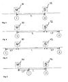
- a network consists of a master 10 (as an example of a first bus subscriber) and a slave 12 (as an example of a second bus subscriber) which are connected to each other via a cable of length L, this is in Fig. 1 shown.
- the request telegram is sent out by the master 10 and received by the slave after the runtime T L. After a certain delay time (T res (slave)), this sends the response which arrives at the master after the same time T L. This is in Fig. 2 illustrated.
- T res (slave) the response time the slave takes after receiving the telegram until it sends the response.
- the invention provides a method which records different signals at different times with successive measurements on the master and on or behind one or more slaves and determines the transit time and thus the distance between master and slave by evaluating the difference between the average response times. If the temporal fluctuations of the response times are statistically distributed, the deviation of the mean value decreases with the number of measurements.
- delays of the measuring devices as well as systematic and statistically distributed fluctuations of the response times of the second bus subscribers, e.g. Slaves, to be filtered out.
- a measurement setup on a data bus with line topology which has a master 10 and a slave 12, may be constructed.
- the two measuring points (1) and (2) need not be arranged directly on the master 10 or on the slave 12. It is sufficient if the measuring points (1) and (2) are arranged on the two sides of the connection between master 10 and slave 12.
- the Measuring structures of Fig. 3, 4 and 5 provide the same result in the method according to the invention.
- Both measuring points (1) and (2) are arranged directly on the master 10 or on the slave 12.
- the average response time is determined, which is assigned to the first bus user (master)
- the average response time is determined, which is assigned to the second bus subscriber (slave).
- the average response time of the slave MW T res (slave)
- the result is twice the runtime.
- the measuring point (2) seen from the master 10 from behind the slave 12, and in measuring construction of the Fig. 5
- the measuring point (1) from the perspective of the slave 12 is arranged behind the master.
- the signals emitted by the master 10 and by the slave 12 arrive delayed at the measuring point (2) so that the same average response time of the slave 12 is measured at the measuring point (2) as in the structure of FIG Fig. 3 ,
- the measured response time does not change if the measurement location is moved to a position outside the connection between master 10 and slave 12 and is located on different sides of the master and slave. How about the Fig. 7 to 10 is explained, this can be exploited to determine the average response times of multiple slaves with one and the same measurement setup.
- Fig. 7 For example, an exemplary topology is illustrated to illustrate that not only line topologies but also branched topologies can be determined with the invention.
- the bus network includes a master 10, 8 slaves 12, denoted S1 through S8, and two repeater stations 14, labeled R1 and R2.
- the total topology is determined sequentially at all bus ends to determine the overall topology.
- the measuring locations (1) to (4) are represented by circles at the respective bus ends.
- the example network consists of three physical segments 20, 22, 24 with one master 12, two repeater stations 14, for example diagnostic repeaters with their own address, and the total of eight slaves 12.
- four bus terminations 30, 32, 34, 36 are provided. which simultaneously serve as measuring positions (1) to (4).
- the main segment 20 consists of the master M and the four slaves S 1 to S4.
- the two comb-shaped branching secondary segments 22, 24 are connected to the main segment 20 via the repeaters R1 and R2.
- the repeater R1 is arranged directly on the slave S1.
- the repeater R2 is connected at a distance d from the slave S3 to the main segment 20.
- the entire topology can be determined with four measurement series, as explained below.
- two series of measurements at the two ends 30, 32 of the main segment 20, at the measuring positions (1) and (2) are performed.
- the distances between the master M and the slaves S1, S2, S3 and S4 can be determined.
- the average response times of the slaves S 1 to S 4 are determined from the perspective of the master, and in the second series of measurements at the measurement position (2), the average response times of the slaves S1, S2, S3 and S4 determined directly, ie without the additional propagation delay between master and Slaves.
- the run times and thus the distances between the master and the individual slaves can then be calculated.
- the slaves S5 to S8 which lie on the secondary segments 22, 24 of the data bus.
- the distance of the associated branch is also determined, ie the distance of the slave S3 plus the distance d. From the agreement of the distances for the slaves S5 and S6, it can first be concluded that they lie on a secondary segment. The same applies to the slaves S7 and S8. The distances determined for these slaves thus result in each case the distance from the master M to the associated branching of the secondary segment 22, 24.
- the series of measurements at the measuring points (1) and (2) results in the Fig. 8 shown topology image. The stations drawn above each have the same calculated distance to the master M.
- repeater station R1 The repeater functionality of repeater station R1 can not be detected directly by the measurement. This repeater station R1 makes itself felt by an additional propagation delay and, if the repeater station is not known, by a greater distance to the slaves S5 and S6.
- Fig. 10 shows the topology image that results after performing measurements on all four measurement positions (1) to (4).
- N + 1 measurement data sets are derived for determining the overall topology of a data bus with N segments.
- N x (N + 1) / 2 pairs of measurements are evaluated.
- the true distance of a slave from the master is the maximum of all detected distances for that slave.
- a smaller than the maximum distance for a slave gives an indication of the distance of a branch of a bus segment on which the slave is located.
- this is also the case an indication that these slaves are in the same subsegment with respect to the two measuring positions or are located directly at the branch.
- the final distance vector then results from the maximum of all distances determined for the slaves: L ⁇ 1 L ⁇ 2 L ⁇ 3 L ⁇ 4 L ⁇ 5 L ⁇ 6 L ⁇ 7 L ⁇ 8th
- the method according to the invention can use a topology image which brings the determined range vectors into a form suitable for displaying the topology.
- M telegram pairs that is to say request and response telegrams
- M 100.
- the observed telegram pairs are data exchange telegrams, these are converted, for example, into a PROFIBUS network once per input / output cycle, the duration of an input-output cycle may be on the order of 10 to 100 ms. If, for example, 30 slaves are connected in line to the fieldbus system, a response time per slave can be determined within 300 to 3000 ms under this condition.
- the required measurement time at each measurement point is approximately 0.5 to 5 minutes.
- the measurement does not intervene in the data exchange on the fieldbus, but monitors the data traffic on, for example, the data exchange telegrams.
- Fig. 11 and 12 show exemplary flow diagrams for performing a first and a second series of measurements for detecting response times at the master or on the slave. To the right of the flowchart, the individual events are shown on a timeline, but this is not to scale.
- the counter is used to determine the number of response times to be included in the averaging.
- a master sends a request telegram (step 42) to a slave device, which is received by a measuring device virtually at the same time.
- the measuring device at the measuring point which is assigned to the master device, generates on its next clock edge a first time stamp Z S (master).
- T L which depends on the distance between master and slave
- the slave device receives in step 46 the request telegram.
- the request telegram has a predetermined length of x bit times, in the case of the FDL status telegram according to the PROFIBUS standard 66 bit times. Furthermore, a minimum wait time is defined for each slave before it can send a response; this is 11 bit times in the selected embodiment of the PROFIBUS standard.
- the slave sends in a next step 48 at a time T S (slave), the earliest 77 bit times after the reception time T E (slave) is in the selected embodiment, an answer telegram. This is received by the master after the propagation time T L at a reception time T E (master) (step 50). Practically at the same time, the measuring device also receives the response telegram and generates on its next clock edge a second time stamp Z E (master) in step 52.
- step 56 it is checked whether a predetermined number of measurements has already been performed; ie m ⁇ M?, where M is 100, for example. If not, the measurement loop goes back to step 42 to observe another input / output cycle. If a sufficient number of measurements have taken place, then the recorded transmission and reception times at the master or the corresponding time stamps Z S (master) and Z E (master) of the measuring device for calculating the average response times are transmitted in step 58. For averaging, a known mean algorithm, such as arithmetic mean, may be used.
- the meter When the measurement for one or more slave devices on the master is completed, the meter can be disconnected from the master and connected to or behind one of the slaves.
- the measuring procedure on the slave is in Fig. 12 shown.
- the measurement process begins when the slave receives the first defined request telegram at a time T E (slave), as shown in step 62.
- the measuring device also receives the telegram and in step 64 generates a first time stamp Z E (slave).
- the slave sends in step 66 after the complete reception of the request telegram and the defined waiting time, as explained above, at a time T S (slave) its response telegram. This is in turn received by the measuring device at the same time, which generates a second time stamp Z S (slave) in step 68.
- a query is made as to whether a predetermined number of measurements have already been taken, m ⁇ M?. If not, the meter goes through another measurement cycle and goes back to step 62. If so, the determined response times, Z S - Z E , are passed to an averaging algorithm, which is executed in step 76. The mean value is calculated in the same way as the average response time at the master. This completes the determination of the average response time of a slave.
- the average response times are then subtracted to master and slave to determine the propagation delay between master and slave.
- the timestamp generated by the meter should be sufficiently accurate and subject to no temporal drift, for example, temperature changes. Furthermore, the sampling rate of the meter should be sufficiently high, so that a high time resolution is guaranteed.
- bus state that is to say the overall state of the connected devices and their activities, does not change between the measurements.
- ambient temperature humidity and the like.
Description
Die Erfindung betrifft ein Verfahren zur Bestimmung der Topologie eines seriellen asynchronen Datenbusses, an den wenigstens ein erster Busteilnehmer und eine zweiter Busteilnehmer angeschlossen sind, die über ein vorgegebenes Bus-Zugriffsprotokoll kommunizieren.The invention relates to a method for determining the topology of a serial asynchronous data bus, to which at least a first bus subscriber and a second bus subscriber are connected, which communicate via a predetermined bus access protocol.
Die Erfindung ist grundsätzlich anwendbar auf alle seriellen Datenbusse, insbesondere auf Feldbussysteme, wie PROFIBUS, Fieldbus Foundation, aber auch Ethernet und andere bekannte Feldbussysteme. Ein Feldbus verbindet in einer Anlage Feldgeräte wie Sensoren und Aktoren, auch als Slaves bezeichnet, zur Kommunikation und Steuerung mit einem Steuerungsgerät, auch als Master bezeichnet. Da mehrere Teilnehmer Nachrichten über dieselbe Leitung senden, ist für jedes Feldbussystem ein normiertes Bus-Zugriffsprotokoll festgelegt.The invention is fundamentally applicable to all serial data buses, in particular fieldbus systems such as PROFIBUS, Fieldbus Foundation, but also Ethernet and other known fieldbus systems. A fieldbus connects in a system field devices such as sensors and actuators, also referred to as slaves, for communication and control with a control device, also referred to as master. Since several users send messages over the same line, a standardized bus access protocol is defined for each fieldbus system.
In der Regel umfasst ein Feldbussystem wenigstens ein Master-Feldgerät (Master) zur Steuerung der Anlage sowie eine Vielzahl von Slave-Feldgeräten (Slaves). Jeder Busteilnehmer wird durch eine zugeordnete eindeutige Adresse angesprochen. Die Kommunikation in einem Feldbussystem erfolgt über Bus-spezifische Telegramme oder Datenpakete oder Datenframes, wobei der Master in der Regel die Kommunikation steuert und Anfrage-Telegramme sendet, auf welche die Slaves mit Antwort-Telegrammen reagieren.In general, a fieldbus system comprises at least one master field device (master) for controlling the system and a plurality of slave field devices (slaves). Each bus participant is addressed by an assigned unique address. Communication in a fieldbus system takes place via bus-specific telegrams or data packets or data frames, whereby the master usually controls the communication and sends request telegrams to which the slaves react with response telegrams.
In der Regel weisen Feldbussysteme eine komplexe Netzwerktopologie mit einer großen Anzahl von Bussegmenten und Busteilnehmern auf. Z.B. ein PROFIBUS DP-Netz kann bis zu 127 Teilnehmer haben, wobei an einzelnen Bussegmenten einer Busleitung bis zu 32 Teilnehmer angeschlossen sein können. Innerhalb des Netzwerkes werden die einzelnen Bussegmente mittels Leitungstreibern, sogenannten Repeatern, verbunden. Um eine Diagnose und Fehleranalyse in einem solchen Bussystem vornehmen zu können, ist es notwendig, dass die Netztopologie des Bussystems, d.h. die Anordnung der Bussegmente und der Teilnehmer an den einzelnen Bussegmenten, bekannt ist. Bei der Fehlersuche z.B. sollten die angeschlossenen Geräte bei der Betrachtung der Signalqualität möglichst in der Reihenfolge ihrer Entfernung zum Messgerät betrachtet werden, damit der richtige Fehlerort bestimmt werden kann. Auch für die Planung physikalischer Messungen sollte die Topologie des Feldbusses bekannt sein, weil Messungen am Besten von den Enden und der Mitte der einzelnen Bussegmente durchgeführt werden. Wenn die Reihenfolge und Länge der Bussegmente und die Anschlussstellen der Geräte an den Segmenten nicht bekannt sind, kann eine Messung nicht sinnvoll geplant werden.In general, fieldbus systems have a complex network topology with a large number of bus segments and bus subscribers. For example, A PROFIBUS DP network can have up to 127 subscribers, whereby up to 32 subscribers can be connected to individual bus segments of a bus line. Within the network, the individual bus segments are connected by means of line drivers, so-called repeaters. In order to make a diagnosis and error analysis in such a bus system, it is necessary that the network topology of the bus system, i. the arrangement of the bus segments and the participants in the individual bus segments, is known. When troubleshooting e.g. If possible, the connected devices should be considered in the order of their distance from the meter when considering the signal quality so that the correct location of the fault can be determined. Also for the planning of physical measurements the topology of the fieldbus should be known, because measurements are best carried out by the ends and the middle of the individual bus segments. If the order and length of the bus segments and the connection points of the devices to the segments are not known, a measurement can not be reasonably planned.
Da Feldbussysteme häufig "gewachsene", schlecht dokumentierte Strukturen haben, liegen häufig auch nicht ausreichende Kenntnisse über die Bustopologie vor. Da jedoch die Leitungen der Feldbussysteme oftmals in Kabelschächten verlegt sind, welche nicht einsehbar sind, ist es in der Regel auch nicht möglich, die Leitungen eines Bussystems unmittelbar nachzuverfolgen und einfach auszumessen. Es wurden daher verschiedene Messverfahren zur Bestimmung der Topologie von Feldbussen entwickelt.Since fieldbus systems often have "grown", poorly documented structures, there is often insufficient knowledge of the bus topology. However, since the lines of the fieldbus systems are often laid in cable ducts, which are not visible, it is usually not possible to track the lines of a bus system immediately and easy to measure. Therefore, different measuring methods for determining the topology of fieldbuses have been developed.
Bei bekanntem Widerstandsbelag eines Kabels der Busleitung kann die Bustopologie auf der Grundlage von Gleichstrommessungen erfasst werden, indem nach und nach die einzelnen Busteilnehmer angepeilt werden und die Länge der Leitung vom Messpunkt bis zum Busteilnehmer über den Gleichstromwiderstand der Leitung ermittelt wird. Dieses Verfahren liefert nur ungenaue Ergebnisse, weil unbekannte Einflussgrößen wie die Übergangswiderstände zwischen Steckern und Kabeln, das Messergebnis verfälschen.With a known resistance pad of a cable of the bus line, the bus topology can be detected on the basis of DC measurements by gradually targeted the individual bus participants and the length of the line from the measuring point to the bus subscriber on the DC resistance of the line is determined. This method provides only inaccurate results, because unknown factors such as the contact resistance between plugs and cables, distort the measurement result.
Ein präziseres bekanntes Messverfahren ist reflexionsbasierte Laufzeitmessung, die abhängig von der bekannten Ausbreitungsgeschwindigkeit der Messsignale die Kabellänge ermittelt. Diese Reflexions-Messverfahren sind aktive Messverfahren, d.h. sie senden aktiv Signale auf den Bus und erfassen die reflektierten Signale. Dies bedeutet, dass die Messverfahren möglichst nur am ruhenden Bus ausgeführt werden, weil die gesendeten Testsignale den laufenden Betrieb des Feldbus stören würden. Es sind zwar auch Verfahren bekannt, die während des regulären Busbetriebs aktiv Messungen durchführen, indem sie die von dem Buszugriffsprotokoll vorgesehene Übertragungspausen für die Messung nutzen; diese Verfahren bergen jedoch immer die Gefahr, dass die gesendeten Signale dennoch die Kommunikation stören.A more precise known measuring method is reflection-based transit time measurement, which determines the cable length depending on the known propagation speed of the measuring signals. These reflection measurement methods are active measurement methods, i. they actively send signals to the bus and detect the reflected signals. This means that the measuring methods are only executed on the stationary bus, if possible, because the transmitted test signals would disturb the ongoing operation of the fieldbus. Although methods are known which actively perform measurements during regular bus operation by taking advantage of the transmission pauses provided by the bus access protocol for the measurement; However, these methods always involve the risk that the transmitted signals still disturb the communication.
Aus der
Die
Die
Die Diagnose-Verfahren zur Bestimmung der Bustopologie des Standes der Technik basieren somit fast ausschließlich auf Reflexionsmessungen. Die einzige Ausnahme stellt das Verfahren zur Messung des elektrischen Widerstandes der Leitung dar. Die meisten Reflexionsmessungen sowie das elektrische Verfahren setzen einen ruhenden Bus voraus. Diese Messungen können also nicht im laufenden Betrieb durchgeführt werden. Die Genauigkeit der Reflexionsmessung nimmt mit zunehmender Baudrate der Datenübertragung ab.The diagnostic methods for determining the bus topology of the prior art are thus based almost exclusively on reflection measurements. The only exception is the method for measuring the electrical resistance of the line. Most reflectance measurements and the electrical process require a quiescent bus. These measurements can therefore not be carried out during operation. The accuracy of the reflection measurement decreases with increasing baud rate of the data transmission.
Eine andere Art eines Diagnoseverfahrens für ein Feldbussystem ist aus der
Schließlich offenbart das US-Patent
Der Erfindung liegt die Aufgabe zugrunde, ein Verfahren zur Bestimmung der Topologie eines seriellen asynchronen Datenbusses anzugeben, das die oben beschriebene Nachteile des Standes der Technik vermeidet und eine zuverlässige Ermittlung der Topologie erlaubt, ohne hierfür den laufenden Betrieb des Datenbusses unterbrechen zu müssen oder zu stören.The invention has for its object to provide a method for determining the topology of a serial asynchronous data bus, which avoids the disadvantages of the prior art described above and allows a reliable determination of the topology, without having to interrupt the ongoing operation of the data bus or disturb ,
Die Erfindung löst die vorstehende Aufgabe mit dem in Anspruch 1 angegebenen Verfahren. Vorteilhafte Ausgestaltungen sind in den abhängigen Ansprüchen angegeben.The invention achieves the above object with the method specified in
Die Erfindung sieht ein Verfahren zur Bestimmung der Topologie eines seriellen asynchronen Datenbusses vor, wobei wenigstens ein erster Busteilnehmer und ein zweiter Busteilnehmer an den Datenbus angeschlossen sind, die über ein vorgegebenen Bus-Zugriffsprotokoll kommunizieren. Das Protokoll umfasst definierte Anfrage- und Antworttelegramme. Insbesondere betrifft die Erfindung ein Feldbussystem, an das wenigstens ein Master-Gerät als erster Busteilnehmer und mehrere Slave-Geräte als zweite Busteilnehmer angeschlossen sind. Der erste Busteilnehmer, z.B. der Master, sendet Anfrage-Telegramme, die von dem zweiten Busteilnehmer, z.B. einem Slave, empfangen werden. Dieser sendet in Reaktion auf jedes Anfrage-Telegramm jeweils ein Antwort-Telegramm, und die Antwort-Telegramme werden wiederum von dem ersten Busteilnehmer empfangen. Erfindungsgemäß werden die zeitlichen Differenzen zwischen dem Empfangen eines jeweiligen Anfrage-Telegramms des ersten Busteilnehmers und dem Empfangen des zugehörigen Antwort-Telegramms des zweiten Busteilnehmers an einer ersten Messstelle an dem Datenbus ermittelt, die sich aus der Zeitverzögerungen zwischen Antwort-und Anfragetelegramm an der Messstelle ergeben (erste Vielzahl von zeitlichen Differenzen). Die erste Messstelle kann direkt an dem ersten Busteilnehmer oder, vom zweiten Busteilnehmer aus gesehen, hinter dem ersten Busteilnehmer liegen. Eine erste mittlere Antwortzeit wird aus der ersten Vielzahl der bestimmten Differenzen berechnet. Erfindungsgemäß werden weiterhin die zeitlichen Differenzen zwischen dem Empfangen des jeweiligen Anfrage-Telegramms des ersten Busteilnehmers und dem Empfangen des zugehörigen Antwort-Telegramms des zweiten Busteilnehmers an einer zweiten Messstelle an dem Datenbus ermittelt (zweite Vielzahl von zeitlichen Differenzen). Die zweite Messstelle kann direkt an dem zweiten Busteilnehmer oder, vom ersten Busteilnehmer aus gesehen, hinter dem zweiten Busteilnehmer liegen. Eine zweite mittlere Antwortzeit wird aus der zweiten Vielzahl der bestimmten Differenzen berechnet. Aus der Differenz der ersten mittleren Antwortzeit und der zweiten mittleren Antwortzeit kann erfindungsgemäß die Laufzeitverzögerung und somit die Distanz zwischen dem ersten Busteilnehmer und dem zweiten Busteilnehmer abgeleitet werden.The invention provides a method for determining the topology of a serial asynchronous data bus, wherein at least a first bus subscriber and a second bus subscriber are connected to the data bus, which communicate via a predetermined bus access protocol. The protocol includes defined request and response telegrams. In particular, the invention relates to a field bus system to which at least one master device as the first bus subscriber and several slave devices are connected as a second bus subscriber. The first bus user, eg the master, sends request telegrams that are received by the second bus user, eg a slave. This sends in response to each request telegram each a response telegram, and the response telegrams are in turn received by the first bus subscriber. According to the invention, the time differences between receiving a respective request telegram of the first bus subscriber and receiving the associated response telegram of the second bus subscriber at a first measuring point on the data bus are determined, resulting from the time delays between response and request telegram at the measuring point (first multiplicity of temporal differences). The first measuring point can lie directly behind the first bus subscriber or, as seen by the second bus subscriber, behind the first bus subscriber. A first average response time is calculated from the first plurality of determined differences. According to the invention, the time differences between receiving the respective request telegram of the first bus subscriber and receiving the associated response telegram of the second bus subscriber at a second measuring point on the data bus determined (second plurality of time differences). The second measuring point can be located directly at the second bus subscriber or, viewed from the first bus subscriber, behind the second bus subscriber. A second average response time is calculated from the second plurality of determined differences. From the difference of the first average response time and the second average response time, the propagation delay and thus the distance between the first bus subscriber and the second bus subscriber can be derived according to the invention.
Die zweite mittlere Antwortzeitkann kann nach demselben Messprinzip in demselben Verfahrenszyklus ermittelt werden wie die erste mittlere Antwortzeit. Oder sie kann vorab für jeden zweiten Busteilnehmer ermittelt und in Form einer zusätzlichen Datenbasis vorgehalten werden. Die Vorabermittlung der mittleren Antwortzeit für den zweiten Busteilnehmer kann nach dem oben beschriebenen oder nach einem anderen Messprinzip erfolgen.The second average response time can be determined according to the same measurement principle in the same process cycle as the first average response time. Or it can be determined in advance for each second bus subscriber and stored in the form of an additional database. The advance determination of the average response time for the second bus subscriber can be carried out according to the method described above or according to another measuring principle.
Die erste und die zweite Messstelle liegen vorzugsweise an den Busenden. Die Abstände zwischen dem Master und allen zwischen den beiden Messstellen befindlichen Slaves können dann ermittelt werden.The first and second measuring points are preferably at the bus ends. The distances between the master and all slaves located between the two measuring points can then be determined.
Die Erfindung beruht somit auf der Bestimmung der mittleren Antwortzeiten, die von bestimmten Positionen aus gemessen werden, und erlaubt, hieraus die Signallaufzeiten und damit die Entfernung zwischen Busteilnehmern zu bestimmen. Im einfachsten Fall einer Linientopologie des Datenbusses, mit einem Master an einem Ende des Busses und mehreren in Reihe geschalteten Slaves, genügen zur Realisierung der Erfindung zwei Messreihen. Eine Messreihe wird direkt am Master, oder von den Slaves aus gesehen hinter dem Master, durchgeführt und eine Messreihe wird an oder, vom Master aus gesehen, hinter dem letzten Slave in der Reihe durchgeführt. An jeder Messstelle wird eine Messreihe für jeden Slave durchgeführt, in der die zeitlichen Differenzen von Anfrage- und Antwort-Telegrammpaaren, die diesem Slave zugeordnet sind, erfasst werden und hieraus eine mittlere Antwortzeit für jeden Slave berechnet wird, und zwar jeweils aus Sicht der ersten Messstelle und aus Sicht der zweiten Messstelle. Die Differenz der mittleren Antwortzeiten an den beiden Messpositionen erlaubt die Bestimmung der Signallaufzeit zwischen dem ersten Busteilnehmer, z.B. dem Master, und jedem zweiten Busteilnehmer, z.B. den Slaves.The invention is thus based on the determination of the average response times, which are measured from certain positions, and allows to determine therefrom the signal propagation times and thus the distance between bus subscribers. In the simplest case of a line topology of the data bus, with a master at one end of the bus and several slaves connected in series, two series of measurements suffice to implement the invention. A measurement series is performed directly on the master, or as seen from the slaves behind the master, and a series of measurements is performed on or, viewed from the master, behind the last slave in the series. At each measuring point, a series of measurements is carried out for each slave, in which the time differences of request and response telegram pairs assigned to this slave are detected and from this a mean response time is calculated for each slave, in each case from the point of view of the first one Measuring point and from the point of view of the second measuring point. The difference between the average response times at the two measurement positions allows the determination of the signal propagation time between the first bus user, eg the master, and every second bus user, eg the slaves.
Erfindungsgemäß müssen die Messungen an den verschiedenen Messstellen nicht synchron durchgeführt werden, sondern sie können nacheinander unter Verwendung eines Messgeräts durchgeführt werden, das nacheinander an der ersten und der zweiten Messstelle angeschlossen wird.According to the invention, the measurements at the different measuring points need not be carried out synchronously, but they can be carried out successively using a measuring device which is connected in succession to the first and the second measuring point.
Erfindungsgemäß müssen die Messungen auch nicht direkt am ersten und am zweiten Busteilnehmer, also z.B. am Master oder am Slave vorgenommen werden. Wie oben dargelegt, sollten die Messungen jedoch außerhalb der Verbindung zwischen Master und Slave und auf verschiedenen Seiten dieser Verbindung liegen. Bei der Differenzbildung zur Ermittlung der Laufzeitverzögerung kürzen sich dann die Kabelstrecken, die vom Anfrage-Telegramm und vom Antwort-Telegramm zum Messgerät hin gleichermaßen durchlaufen werden, heraus. Wie ebenfalls dargelegt, ist es für die Messung der Abstände mehrerer Slaves, die in Reihe hintereinander geschaltet sind, ausreichend, eine Messung am Master und eine Messung am oder hinter dem letzten Slave in der Reihe durchzuführen. Eine Messung an jedem Slave ist dagegen nicht notwendig. Wenn die mittleren Antwortzeiten der Slaves vorab ermittelt wurden, genügt die Durchführung einer Messreihe an dem oder in der Nähe des Masters.According to the invention, the measurements do not have to be made directly at the first and second bus subscribers, e.g. be made on the master or on the slave. However, as stated above, the measurements should be outside the master-slave connection and on different sides of that connection. When subtracting to determine the propagation delay, the cable lengths that are passed through equally from the request telegram and the response telegram to the meter are then cut out. As also stated, in order to measure the distances of several slaves connected in series, it is sufficient to perform one measurement on the master and one measurement on or behind the last slave in the series. A measurement on each slave, however, is not necessary. If the average response times of the slaves have been determined in advance, it is sufficient to carry out a series of measurements at or near the master.
Das erfindungsgemäße Verfahren kann während des laufenden Datenverkehrs durchgeführt werden und wertet die Sende- und Empfangszeiten definierter Anfrage- und Antwort-Telegramme aus, die regelmäßig über den Datenbus ausgetauscht werden. Besonders geeignet für die Zwecke der Erfindung sind Telegramme, die oft und an möglichst viele Teilnehmer verschickt werden. Bei PROFIBUS sind das zum Beispiel die Datenaustausch- und die FDL (Fieldbus Data Layer)-Status-Telegramme. Die Datenaustauschtelegramme werden in jedem PROFIBUS-Zyklus an jeden konfigurierten Busteilnehmer verschickt. Da die Zykluszeiten hier oft im Millisekundenbereich liegen, können in kurzer Zeit viele Messungen durchgeführt werden. Das FDL-Status-Telegramm dagegen hat den Vorteil, dass es an jede Adresse gesendet wird, eine feste Größe hat und oft schon von der Hardware des Busteilnehmers beantwortet wird. Dadurch kann man alle Geräte erfassen und die Antwortzeiten sind im Regelfall weniger breit gestreut als bei den komplexeren Telegrammtypen. Erfindungsgemäß ist es jedoch auch möglich, das Verfahren auf andere Arten von Telegrammen zu stützen.The method according to the invention can be carried out during the current data traffic and evaluates the transmission and reception times of defined request and response telegrams which are regularly exchanged over the data bus. Particularly suitable for the purposes of the invention are telegrams that are often sent to as many participants as possible. For PROFIBUS, these are, for example, the data exchange and the FDL (Fieldbus Data Layer) status telegrams. The data exchange telegrams are sent to every configured bus participant in each PROFIBUS cycle. Since the cycle times are often in the millisecond range, many measurements can be carried out in a short time. The FDL status telegram, on the other hand, has the advantage that it is sent to every address is, has a fixed size and is often already answered by the hardware of the bus station. This makes it possible to record all devices and the response times are generally less widely dispersed than in the more complex telegram types. However, according to the invention it is also possible to base the method on other types of telegrams.
Durch die Erfassung einer Vielzahl von Antwortzeiten an zwei unterschiedlichen Positionen innerhalb des Datenbus-Netzes und die Auswertung der mittleren Antwortzeiten ist es erfindungsgemäß möglich, Verzögerungen und zeitliche Schwankungen beim Senden von Antwort-Telegrammen, die nicht laufzeitbedingt sind, herauszufiltern. Die Laufzeitverzögerung TL zwischen dem ersten und dem zweiten Busteilnehmer kann erfindungsgemäß wie folgt berechnet werden: ![]()
![]()
Sind die Antwortzeiten näherungsweise standardverteilt, so nimmt die Unsicherheit des Mittelwertes mit zunehmender Anzahl von Messwerten ab. Eine erste Schätzung des Fehlers der mittleren Antwortzeit MW(T) ist gegeben durch: ![]()
![]()
Sofern ein Datenbus oder Datenbusabschnitt eine Linien-Topologie aufweist, kann aus den Laufzeitverzögerungen zwischen dem Master-Gerät und den mehreren Slave-Geräten jeweils unmittelbar die Reihenfolge der Slave-Geräte entlang des Datenbusses ermittelt werden. Wird für mehrere Slave-Geräte dieselbe oder nahezu dieselbe Laufzeit ermittelt, so ist dies ein Hinweis auf eine Datenbusabzweigung. Erfindungsgemäß werden dann die folgenden weiteren Verfahrensschritte ausgeführt: Bestimmen einer Vielzahl zeitlicher Differenzen für ein Slave-Gerät zwischen dem Empfangen von Anfrage-Telegrammen und dem Senden von zugehörigen Antwort-Telegrammen an einer dritten Messstelle an dem Datenbus, die dem Slave-Gerät zugeordnet ist, wobei die dritte Messstelle hinter der Datenbusabzweigung an dem Slave-Gerät oder, vom Master-Gerät aus gesehen, hinter dem Slave-Gerät liegt, und Berechnen einer mittleren Antwortzeit, die dem Slave-Gerät zugeordnet ist, das in der Datenbusabzweigung liegt, aus der Vielzahl der für das Slave-Gerät bestimmten Differenzen. Für jede Abzweigung des Datenbusses wird erfindungsgemäß eine zusätzliche Messreihe durchgeführt, wobei die zweite, dritte und jede weitere Messstelle vorzugsweise immer an dem Ende des jeweiligen abzweigenden Bussegments angeordnet wird.If a data bus or data bus section has a line topology, the sequence of the slave devices along the data bus can be determined directly from the propagation delays between the master device and the multiple slave devices. If the same or almost the same runtime is determined for several slave devices, this is an indication of a data bus branch. According to the invention, the following further method steps are then carried out: determining a plurality of time differences for a slave device between receiving request telegrams and transmitting associated response telegrams at a third measuring point on the data bus associated with the slave device, wherein the third point of measurement is behind the data bus branch on the slave device or, as seen from the master device, behind the slave device, and calculating an average response time associated with the slave device that is in the data bus branch from the slave device Variety of differences for the slave device. For each branch of the data bus an additional series of measurements is carried out according to the invention, wherein the second, third and each further measuring point is preferably always arranged at the end of the respective branching bus segment.
Erfindungsgemäß werden alle Messungen vorzugsweise unter gleichen Betriebsbedingungen in Bezug auf Zustand und physikalische Parameter des Datenbusses ausgeführt.According to the invention, all measurements are preferably carried out under the same operating conditions with regard to the state and physical parameters of the data bus.
Das erfindungsgemäße Verfahren kann durch zunehmend mehr Messungen die Genauigkeit der Distanzbestimmung erhöhen. Erfindungsgemäß werden der erste und der zweite Mittelwert jeweils aus wenigstens 20 Antwortzeiten abgeleitet, vorzugsweise jedoch aus wenigstens 50 oder sogar aus wenigstens 100 Antwortzeiten. Es ist auch möglich, zunächst den ersten und zweiten Mittelwert aus nur relativ wenigen Antwortzeiten zu bilden und mit fortschreitender Messdauer und Erfassung zusätzlicher Antwortzeiten die Mittelwertbildung zu verfeinern.The inventive method can increase the accuracy of the distance determination by increasingly more measurements. According to the invention, the first and second mean values are each derived from at least 20 response times, but preferably from at least 50 or even at least 100 response times. It is also possible first to form the first and second average from only relatively few response times and to refine the averaging as the measurement duration and the acquisition of additional response times progresses.
Während bei den oben beschriebenen Reflexionsmessungen des Standes der Technik die Präzision der Topologiebestimmung mit zunehmenden Baudraten der Datenübertragung abnimmt, hat sich bei der Erprobung der Erfindung gezeigt, dass die Präzision der Topologiebestimmung mit zunehmender Baudrate der Datenübertragung zunimmt. Ein Grund hierfür ist, dass bei zunehmenden Baudraten höhere Abtastfrequenzen zum Einsatz kommen, welche präzisere Zeitstempel und eine bessere zeitliche Auflösung mit sich bringen. Da die Zykluszeiten ebenfalls kürzer sind, ist es möglich, innerhalb derselben Zeiten mehr Messwerte zu ermitteln. Auch ist bei Betrieb mit höheren Baudraten die Schwankungsbreite der Busteilnehmer beim Senden von Antworttelegrammen geringer. Wenn man davon ausgeht, dass die Schwankungsbreite beim Senden von Antworttelegrammen eines Busteilnehmers auch nur innerhalb einer Bitzeit liegt, so beträgt diese Bitzeit bei einer Baudrate von 12 MByte gerade einmal 83 ns, während die Bitzeit bei einer Baudrate von 1,5 MByte schon 667 ns beträgt und bei niedrigeren Baudraten entsprechend höher ist. Unter der Annahme einer Datenausbreitungsgeschwindigkeit, die etwa 60 % der Lichtgeschwindigkeit, also 4,3 ns/m beträgt, entspricht also eine Schwankung der Antwortzeit von einer Bitbreite bei 12 MBaud (83 ns) etwa 19 m und bei 1,5 MBaud (667 ns) etwa 155 m. Schon aus diesem einfachen Vergleich ist ersichtlich, dass die Erfindung mit höheren Übertragungsraten genauere Messungen erzielen sollte.While in the prior art reflectance measurements described above, the precision of topology determination decreases with increasing baud rates of data transmission, In testing the invention, it has been shown that the precision of the topology determination increases with increasing baud rate of the data transmission. One reason for this is that with increasing baud rates, higher sampling frequencies are used, which result in more precise time stamps and better temporal resolution. Since the cycle times are also shorter, it is possible to determine more measured values within the same times. Also, when operating at higher baud rates, the fluctuation range of the bus subscribers when sending response telegrams is lower. If one assumes that the fluctuation range when sending reply telegrams of a bus subscriber is only within one bit time, this bit time is just 83 ns at a baud rate of 12 MB, while the bit time is already 667 ns at a baud rate of 1.5 MB and is correspondingly higher at lower baud rates. Assuming a data propagation speed that is about 60% of the speed of light, ie 4.3 ns / m, a response time variation of one bit width at 12 Mbaud (83 ns) corresponds to about 19 m and 1.5 Mbaud (667 ns) ) about 155 m. Even from this simple comparison, it can be seen that the invention should achieve more accurate measurements with higher transmission rates.
Die Erfindung gibt ein Verfahren zur Bestimmung der Topologien eines seriellen asynchronen Datenbusses an, das auf der Auswertung von Telegrammen des Datenverkehrs beruht, welche während des regulären Busbetriebs ausgetauscht werden. Das erfindungsgemäße Verfahren lässt sich durch einfaches Mithören der Telegramme mit Hilfe eines Messgerätes an wenigstens einer Messstelle an dem Datenbus, sofern die mittleren Antwortzeiten der Slaves bekannt sind, oder an wenigstens zwei Messstellen des Datenbusses, sofern die mittleren Antwortzeiten der Slaves noch ermittelt werden müssen, realisieren. Es ist weder eine besondere Beschaltung des Datenbusses notwendig, noch müssen für die Laufzeitmessung und Topologiebestimmung besondere Messtelegramme oder andere Messsignale auf den Datenbus gesandt werden. Praktische Versuche mit dem erfindungsgemäßen Verfahren haben gezeigt, dass schon mit kurzen Messzyklen präzise und zuverlässige Ergebnisse erhalten werden können.The invention provides a method for determining the topologies of a serial asynchronous data bus, which is based on the evaluation of telegrams of data traffic, which are exchanged during regular bus operation. The inventive method can be by simply listening to the telegrams using a meter at least one measuring point on the data bus, if the average response times of the slaves are known, or at least two measuring points of the data bus, if the mean response times of the slaves still need to be determined realize. Neither a special wiring of the data bus is necessary, nor do special measuring telegrams or other measuring signals have to be sent to the data bus for the transit time measurement and topology determination. Practical experiments with the method according to the invention have shown that even with short measuring cycles precise and reliable results can be obtained.
Die Erfindung ist im Folgenden mit weiteren Einzelheiten anhand eines Ausführungsbeispiels mit Bezug auf die Zeichnungen näher erläutert. In den Figuren zeigen:
- Fig. 1
- eine vereinfachte schematische Darstellung eines Feldbusses mit einem Master und einem Slave;
- Fig. 2
- eine vereinfachte schematische Darstellung der Signallaufzeiten zwischen dem Master und dem Slave des Feldbussystems der
Fig. 1 ; - Fig. 3
- eine vereinfachte schematische Darstellung eines Feldbusses mit einem Master und einem Slave zur Erläuterung der Erfindung;
- Fig. 4
- eine ähnliche Darstellung wie
Fig. 3 zur Erläuterung eines ersten Messaufbaus gemäß der Erfindung; - Fig. 5
- eine ähnliche Darstellung wie
Fig. 3 zur Erläuterung eines zweiten Messaufbaus gemäß der Erfindung; - Fig. 6
- eine ähnliche Darstellung wie
Fig. 3 zur Erläuterung eines weiteren Messaufbaus; - Fig. 7
- ein Beispiel für die Topologie eines Datenbusses zur Erläuterung des erfindungsgemäßen Verfahrens;
- Fig. 8, 9
und 10 - Topologiebilder, welche sich nach Durchführung von Messreihen an
den Messpositionen 1 und 2, anPosition 3 bzw. anPosition 4 ergeben; - Fig. 11
- ein Ablaufdiagramm eines Ausführungsbeispiels eines ersten Teils des erfindungsgemäßen Verfahrens zur Erfassung von Antwortzeiten am Master; und
- Fig. 12
- ein Ablaufdiagramm eines Ausführungsbeispiels eines zweiten Teils des erfindungsgemäßen Verfahrens zur Erfassung von Antwortzeiten am Slave.
- Fig. 1
- a simplified schematic representation of a field bus with a master and a slave;
- Fig. 2
- a simplified schematic representation of the signal transit times between the master and the slave of the fieldbus system of
Fig. 1 ; - Fig. 3
- a simplified schematic representation of a field bus with a master and a slave to explain the invention;
- Fig. 4
- a similar representation as
Fig. 3 to explain a first measurement structure according to the invention; - Fig. 5
- a similar representation as
Fig. 3 to explain a second measuring structure according to the invention; - Fig. 6
- a similar representation as
Fig. 3 to explain a further measurement setup; - Fig. 7
- an example of the topology of a data bus to explain the method according to the invention;
- FIGS. 8, 9 and 10
- Topology images, which result after measuring series at measuring
positions position 3 or atposition 4; - Fig. 11
- a flowchart of an embodiment of a first part of the inventive method for detecting response times at the master; and
- Fig. 12
- a flowchart of an embodiment of a second part of the inventive method for detecting response times at the slave.
Die Erfindung beruht auf folgenden Überlegungen. Im einfachsten Fall besteht ein Netzwerk aus einem Master 10 (als Beispiel für einen ersten Busteilnehmer) und einem Slave 12 (als Beispiel für einen zweiten Busteilnehmer), die über ein Kabel der Länge L miteinander verbunden sind, dies ist in
Das Anfrage-Telegramm wird vom Master 10 ausgesendet und nach der Laufzeit TL vom Slave empfangen. Dieser sendet nach einer gewissen Verzögerungszeit (Tres(Slave)) die Antwort, die nach der gleichen Laufzeit TL beim Master eintrifft. Dies ist in 
Die Differenz der beiden Antwortzeiten Tres(Master) - Tres (Slave) ergibt die doppelte Laufzeit, gemäß der oben angegebenen Formel (1). Die Entfernung L ergibt sich dann aus: 
Könnte man also dieselben Signale, nämlich die Anfrage- und Antwort-Telegramme, an den beiden Messpunkten an Master und Slave erfassen, so könnte man bei Zugrundelegung eines idealen Systems direkt die Entfernung zwischen Master und Slave ermitteln. Hierzu bräuchte man jedoch zwei oder mehr Messgeräte, um an dem Master und den Slaves die Sende- und Empfangs- bzw. Empfangs- und Sendezeiten für dieselben Anfrage- und Antwort-Telegramme zu erfassen.If one could therefore capture the same signals, namely the request and response telegrams, at the two measuring points on the master and slave, then one could, on the basis of a ideal system directly determine the distance between master and slave. However, this would require two or more measuring devices in order to record the transmission and reception or reception and transmission times for the same request and response telegrams on the master and the slaves.
Die Erfindung schafft ein Verfahren, das mit aufeinanderfolgenden Messungen am Master und an oder hinter einem oder mehreren Slaves verschiedene Signale zu unterschiedlichen Zeitpunkten erfasst und die Laufzeit und somit die Distanz zwischen Master und Slave durch die Auswertung der Differenz der mittleren Antwortzeiten ermittelt. Sofern die zeitlichen Schwankungen der Antwortzeiten statistisch verteilt sind, nimmt die Abweichung des Mittelwertes mit der Anzahl der Messungen ab. Für die Mittelwerte MW der Antwortzeiten gilt in Bezug auf die Messung am Master: 
Unter der Voraussetzung, dass sich die mittlere Antwortzeit des Slaves MW(Tres(Slave)) nicht ändert, kann diese durch eine spätere Messung am Slave ermittelt werden. Die Differenz der mittleren Antwortzeiten ergibt dann die doppelte Laufzeit, gemäß der obigen Formel (1)Assuming that the average response time of the slave MW (T res (slave)) does not change, this can be determined by a later measurement on the slave. The difference of the average response times then gives twice the transit time, according to the above formula (1)
Durch die erfindungsgemäße Mittelwertbildung können Verzögerungen der Messgeräte sowie systematische und statistisch verteilte Schwankungen der Antwortzeiten der zweiten Busteilnehmer, z.B. Slaves, herausgefiltert werden.Due to the averaging according to the invention, delays of the measuring devices as well as systematic and statistically distributed fluctuations of the response times of the second bus subscribers, e.g. Slaves, to be filtered out.
Im Folgenden ist mit Bezug auf die
In dem Messaufbau der
In dem Messaufbau der
Befindet sich dagegen eine Messstelle zwischen Master 10 und Slave 12, wie in
In
Das Beispielsnetz besteht aus drei physikalischen Segmenten 20, 22, 24 mit dem einen Master 12, zwei Repeaterstationen 14, beispielsweise Diagnose-Repeater mit eigener Adresse, und den insgesamt acht Slaves 12. Zusätzlich sind vier Busabschlüsse 30, 32, 34, 36 vorgesehen, die gleichzeitig als Messpositionen (1) bis (4) dienen. Das Hauptsegment 20 besteht aus dem Master M und den vier Slaves S 1 bis S4. Die zwei kammförmig abzweigenden Nebensegmente 22, 24 sind über die Repeater R1 und R2 mit dem Hauptsegment 20 verbunden. Der Repeater R1 ist direkt an dem Slave S1 angeordnet. Der Repeater R2 ist in einem Abstand d von dem Slave S3 am Hauptsegment 20 angeschlossen.The example network consists of three
In diesem Ausführungsbeispiel kann die gesamte Topologie mit vier Messreihen ermittelt werden, wie im Folgenden erläutert ist. Zunächst werden zwei Messreihen an den beiden Enden 30, 32 des Hauptsegmentes 20, an den Messpositionen (1) und (2) durchgeführt. Auf der Grundlage dieser Messreihen können die Abstände zwischen dem Master M und den Slaves S1, S2, S3 und S4 ermittelt werden. In der ersten Messreihe, an Position (1) werden die mittleren Antwortzeiten der Slaves S 1 bis S4 aus Sicht des Masters ermittelt, und in der zweiten Messreihe an der Messposition (2) werden die mittleren Antwortzeiten der Slaves S1, S2, S3 und S4 direkt ermittelt, also ohne die zusätzliche Laufzeitverzögerung zwischen Master und Slaves. Durch Differenzbildung können dann jeweils die Laufzeiten und somit die Abstände zwischen dem Master und den einzelnen Slaves berechnet werden.In this embodiment, the entire topology can be determined with four measurement series, as explained below. First, two series of measurements at the two ends 30, 32 of the
Bei diesem Verfahren ergeben sich auch Werte für die Slaves S5 bis S8, die auf den Nebensegmenten 22, 24 des Datenbusses liegen. Für die Entfernung der Slaves S5 und S6 zum Master M wird nämlich der gleiche Wert berechnet wie für S1, weil die Abzweigung ihres Nebensegments 22 bei S 1 liegt. Für die Entfernung der Slaves S6 und S7 wird ebenfalls die Entfernung des zugehörigen Abzweigs ermittelt, also die Entfernung des Slaves S3 plus die Strecke d. Aus der Übereinstimmung der Entfernungen für die Slaves S5 und S6 kann zunächst geschlossen werden, dass diese auf einem Nebensegment liegen. Das gleiche gilt für die Slaves S7 und S8. Die für diese Slaves ermittelten Abstände ergeben somit jeweils die Entfernung vom Master M zur zughörigen Abzweigung des Nebensegments 22, 24. Durch die Messreihen an den Messstellen (1) und (2) ergibt sich das in
Um die Topologie der Nebensegmente 22, 24 richtig zu ermitteln, werden daher weitere Messreihen an den Messpositionen (3) und (4) durchgeführt. Aufgrund der Messreihen an den Messpositionen (1) und (3) können die korrekten Abstände zwischen dem Master M und den Slaves S5 und S6 ermittelt werden. Für alle anderen Slaves ergibt sich jedoch wiederum die gleiche Entfernung zum Master, nämlich die Entfernung zwischen Master und Slave S1. Hieraus kann geschlossen werden, dass die anderen Stationen S1, S2, S3, S4, S7, S8 in Bezug auf die Verbindung vom Master M zu den Slaves S5 und S6 auf einem Nebensegment liegen, dessen Entfernung zum Master M gleich der Strecke zwischen dem Master M und dem Slave S 1 ist. Um die genaue Entfernung vom Master M zu den Slaves S5 und S6 zu berechnen, muss auch die Verzögerungszeit des Repeaters R1 bekannt sein, weil dessen Verzögerungszeit sonst als zusätzliche Laufzeit gewertet wird und sich eine zu große Entfernung ergibt.In order to correctly determine the topology of the
Die Kombination der Ergebnisse aus den Messreihen an den Messpositionen (1), (2) und (3) ergibt das in
Die Repeaterfunktionalität der Repeaterstation R1 kann durch die Messung nicht direkt erkannt werden. Diese Repeaterstation R1 macht sich durch eine zusätzliche Laufzeitverzögerung und, sofern die Repeaterstation nicht bekannt ist, durch einen größeren Abstand zu den Slaves S5 und S6 bemerkbar.The repeater functionality of repeater station R1 can not be detected directly by the measurement. This repeater station R1 makes itself felt by an additional propagation delay and, if the repeater station is not known, by a greater distance to the slaves S5 and S6.
Bei Durchführung einer weiteren Messreihe an der Messposition (4) können schließlich auch die korrekten Abstände zwischen dem Master M und den Slaves S7 und S8 dargestellt werden. Um die richtige Absolutposition zu berechnen, muss wiederum die Verzögerungszeit der Repeaterstation R2 bekannt sein. In
Für das beschriebene Ausführungsbeispiel gilt, dass zur Bestimmung der Gesamttopologie eines Datenbusses mit N Segmenten N+1 Messdatensätze abgeleitet werden. Für die Ermittlung der Distanzen zwischen Master und Slaves werden N x (N+1)/2 Paare von Messungen, z.B. jeweils an gegenüberliegenden Busenden, ausgewertet. Für jedes Paar von Messungen ergeben sich Entfernungen für jeden Slave von dem Master entlang einer Linie, die in einem Entfernungsvektor dargestellt werden können. Wenn von jedem Busende aus gemessen wird, so ist der wahre Abstand eines Slaves vom Master das Maximum aller ermittelten Abstände für diesen Slave. Ein kleinerer als der maximale Abstand für einen Slave gibt einen Hinweis auf die Entfernung eines Abzweigs eines Bussegments, auf dem der Slave liegt. Wenn bei einer Messserie für mehrere Slaves derselbe Abstand ermittelt wird, ist dies ferner ebenfalls ein Hinweis darauf, dass sich diese Slaves in Bezug auf die beiden Messpositionen in demselben Nebensegment befinden oder direkt an der Abzweigung liegen.For the exemplary embodiment described, N + 1 measurement data sets are derived for determining the overall topology of a data bus with N segments. For the determination of the distances between master and slaves, N x (N + 1) / 2 pairs of measurements, eg at opposite bus ends, are evaluated. For each pair of measurements, there are distances for each slave from the master along a line that can be represented in a range vector. When measured from each bus end, the true distance of a slave from the master is the maximum of all detected distances for that slave. A smaller than the maximum distance for a slave gives an indication of the distance of a branch of a bus segment on which the slave is located. Furthermore, if the same distance is determined for a series of measurements for several slaves, this is also the case an indication that these slaves are in the same subsegment with respect to the two measuring positions or are located directly at the branch.
Wenn man annimmt, dass die Abstände zwischen dem Master M und den Slaves S1, S2, S3, ..., S8 den Strecken L1, L2, L3, ..., L8 entsprechen, so ergibt sich für die Slaves S1, S2, S3, ..., S8 aus den Messdatensätzen an den Messstellen (1) und (2) der Entfernungsvektor zu: 
Aus den Messdatensätzen der Messstellen (1) und (3) ergibt sich: ![]()
![]()
Und aus den Messdatensätzen an den Messstellen (1) und (4) ergibt sich: 
Der endgültige Entfernungsvektor ergibt sich dann aus dem Maximum aller ermittelten Abstände für die Slaves zu: ![]()
![]()
Das erfindungsgemäße Verfahren kann einen Topologie-Bilder verwenden, der die ermittelten Entfernungsvektoren in eine für die Darstellung der Topologie geeignete Form bringt.The method according to the invention can use a topology image which brings the determined range vectors into a form suitable for displaying the topology.
In einem Ausführungsbeispiel sei angenommen, dass zur Berechnung der mittleren Antwortzeiten M Telegramm-Paare, also Anfrage- und Antwort-Telegramme, beobachtet werden, wobei in diesem Ausführungsbeispiel M = 100. Wenn die beobachteten Telegramm-Paare Datenaustauschtelegramme sind, so werden diese beispielsweise in einem PROFIBUS-Netz einmal pro Eingabe/Ausgabe-Zyklus gesandt, wobei die Dauer eines Eingabe-Ausgabe-Zyklus in der Größenordnung von 10 bis 100 ms liegen kann. Wenn an dem Feldbussystem z.B. 30 Slaves in Linie angeschlossen sind, so kann unter dieser Voraussetzung innerhalb von 300 bis 3000 ms eine Antwortzeit pro Slave ermittelt werden. Wenn man weiter davon ausgeht, dass zur Bildung der mittleren Antwortzeit jedes Slaves jeweils 100 Antwortzeiten am Master und 100 Antwortzeiten an oder hinter jedem Slave bestimmt werden sollen, wobei diese Messungen mit einem einzigen Messgerät nacheinander ausgeführt werden, beträgt die benötigte Messzeit an jeder Messstelle rund 0,5 bis 5 Minuten. Dabei greift die Messung nicht in den Datenaustausch auf dem Feldbus ein, sondern beobachtet den Datenverkehr auf z.B. die Datenaustauschtelegramme.In one exemplary embodiment, it is assumed that M telegram pairs, that is to say request and response telegrams, are observed in order to calculate the average response times, in which exemplary embodiment M = 100. If the observed telegram pairs are data exchange telegrams, these are converted, for example, into a PROFIBUS network once per input / output cycle, the duration of an input-output cycle may be on the order of 10 to 100 ms. If, for example, 30 slaves are connected in line to the fieldbus system, a response time per slave can be determined within 300 to 3000 ms under this condition. Assuming that for the formation of the average response time of each slave 100 response times on the master and 100 response times on or behind each slave are to be determined, whereby these measurements are carried out in succession with a single measuring device, the required measurement time at each measurement point is approximately 0.5 to 5 minutes. The measurement does not intervene in the data exchange on the fieldbus, but monitors the data traffic on, for example, the data exchange telegrams.
Die
Im Folgenden ist die Erfassung der Antwortzeiten am Master mit Bezug auf
Das Verfahren zur Ermittlung der mittleren Antwortzeiten jedes Slaves, gemessen am Master, beginnt in einem ersten Schritt 40 mit dem Einstellen eines Zählers auf m = 1, wenn das Messgerät an oder in der Nähe des Masters angeschlossen wird. Der Zähler dient der Bestimmung der Anzahl der Antwortzeiten, die in die Mittelwertbildung einfließen sollen. Zu einem Zeitpunkt TS(Master) sendet ein Master ein Anfrage-Telegramm (Schritt 42) an ein Slave-Gerät, welches praktisch zur gleichen Zeit von einem Messgerät empfangen wird. Im Schritt 44 erzeugt das Messgerät an der Messstelle, die dem Master-Gerät zugeordnet ist, bei seiner nächsten Taktflanke einen ersten Zeitstempel ZS(Master). Nach einer Laufzeit TL, die abhängig ist von der Distanz zwischen Master und Slave, empfängt das Slave-Gerät im Schritt 46 das Anfrage-Telegramm. Das Anfrage-Telegramm hat eine vorgegebene Länge von x Bitzeiten, im Falle des FDL-Status-Telegramms gemäß der PROFIBUS-Norm 66 Bitzeiten. Ferner ist für jeden Slave eine minimale Wartezeit definiert, bevor er eine Antwort senden kann; diese beträgt in dem gewählten Ausführungsbeispiel der PROFIBUS-Norm 11 Bitzeiten. Somit sendet der Slave in einem nächsten Schritt 48 zu einer Zeit TS(Slave), die in dem gewählten Ausführungsbeispiel frühestens 77 Bitzeiten nach der Empfangszeit TE(Slave) liegt, ein Antwort-Telegramm. Dieses wird nach der Laufzeit TL zu einem Empfangszeitpunkt TE(Master) von dem Master empfangen (Schritt 50). Praktisch zum gleichen Zeitpunkt empfängt auch das Messgerät das Antwort-Telegramm und erzeugt bei seiner nächsten Taktflanke einen zweiten Zeitstempel ZE(Master) im Schritt 52.The method for determining the average response times of each slave, measured at the master, begins in a
Damit ist der Austausch und die Erfassung eines Telegramm-Paares abgeschlossen, und im nächsten Schritt 54 wird der Zähler m inkrementiert, also m = m + 1. Im nachfolgenden Schritt 56 wird geprüft, ob bereits eine vorgegebene Anzahl von Messungen durchgeführt wurde; d.h. m ≥ M ?, wobei M beispielsweise 100 beträgt. Wenn dies nicht der Fall ist, geht die Messschleife zurück zu Schritt 42, um einen weiteren Eingabe/Ausgabe-Zyklus zu beobachten. Sind ausreichend viele Messungen erfolgt, so werden die erfassten Sende- und Empfangszeiten am Master bzw. die korrespondierenden Zeitstempel ZS(Master) und ZE(Master) des Messgerätes zur Berechnung der mittleren Antwortzeiten im Schritt 58 übergeben. Zur Mittelwertbildung kann ein bekannter Mittelwert-Algorithmus, wie arithmetisches Mittel, verwendet werden. Zusätzlich ist es möglich, durch Verwenden eines geeigneten Filters Ausreißer, die beispielsweise durch singuläre Ereignisse verursacht sein können, in der Messreihe zu erkennen und vor der Mittelwertbildung herauszufiltern. Es ist auch möglich, durch geeignete Auswertung der Messreihe eine Abweichung in der Verteilung der Messwerte zwischen zwei Messreihen zu erkennen und hieraus gegebenenfalls Rückschlüsse auf eine Veränderung des Buszustands zu treffen.Thus, the exchange and the detection of a telegram pair is completed, and in the
Wenn die Messung für eines oder mehrere Slave-Geräte am Master abgeschlossen ist, kann das Messgerät vom Master getrennt und an oder hinter einen der Slaves angeschlossen werden. Das Messverfahren am Slave ist in
Auch beim Anschließen des Messgerätes an einer zweiten Messposition, die den Slaves zugeordnet ist, wird zunächst ein Zähler auf m = 1 eingestellt, wie in Schritt 60 dargestellt. Das Messverfahren beginnt, wenn der Slave das erste definierte Anfrage-Telegramm zu einer Zeit TE(Slave) empfängt, wie in Schritt 62 dargestellt ist. Zur gleichen Zeit empfängt auch das Messgerät das Telegramm und erzeugt im Schritt 64 einen ersten Zeitstempel ZE(Slave). Der Slave sendet im Schritt 66 nach dem vollständigen Empfang des Anfrage-Telegramms und der definierten Wartezeit, wie oben erläutert, zu einer Zeit TS(Slave) sein Antwort-Telegramm. Dieses wird wiederum zur gleichen Zeit von dem Messgerät empfangen, welches im Schritt 68 einen zweiten Zeitstempel ZS(Slave) erzeugt. Wenn das Messgerät entfernt von dem Slave angeschlossen ist, empfängt es das Anfrage- und das Antwort-Telegramm jeweils nach einer gleichen Verzögerungszeit, so dass sich dieselbe Antwortzeit ZS-ZE ergibt. Damit ist ein Messzyklus am Slave abgeschlossen, und im Schritt 70 wird der Zähler inkrementiert, d.h. m = m + 1. In einem nächsten Schritt 72 wird abgefragt, ob bereits eine vorgegebene Anzahl von Messungen erfolgt ist, m ≥ M ?. Wenn nein, durchläuft das Messgerät einen weiteren Messzyklus und geht zurück zu Schritt 62. Wenn ja, werden die ermittelten Antwortzeiten, ZS - ZE, an einen Algorithmus zur Mittelwertbildung übergeben, der im Schritt 76 ausgeführt wird. Der Mittelwert wird auf dieselbe Weise berechnet wie die mittlere Antwortzeit am Master. Damit ist die Bestimmung der mittleren Antwortzeit eines Slaves abgeschlossen.Also, when connecting the measuring device to a second measuring position, which is assigned to the slaves, a counter is initially set to m = 1, as shown in
Wie oben erläutert, werden anschließend die mittleren Antwortzeiten an Master und Slave subtrahiert, um die Laufzeitverzögerung zwischen Master und Slave zu ermitteln.As explained above, the average response times are then subtracted to master and slave to determine the propagation delay between master and slave.
Theoretisch kann durch eine Verlängerung der Messzeit eine beliebige Genauigkeit der Entfernungsmessung erreicht werden. In der Praxis wird die erreichbare Genauigkeit durch geräteinterne Vorgänge in den Busteilnehmern limitiert sein. Zum Beispiel sind alle gängigen Oszillatoren, die als Taktgeber in den Geräten verwendet werden, bis zu einem gewissen Grad temperaturabhängig. Je nach Wärmeentwicklung der elektronischen Bauteile im Slave können hier Variationen des Taktes zu leichten Veränderungen des Antwortverhaltens führen.Theoretically, by extending the measuring time any accuracy of the distance measurement can be achieved. In practice, the achievable accuracy will be limited by device-internal processes in the bus subscribers. For example, all common oscillators used as clocks in the devices are temperature dependent to some extent. Depending on the heat development of the electronic components in the slave, variations in the clock can lead to slight changes in the response behavior.
Eine wichtige Voraussetzung für die Anwendbarkeit des Verfahrens ist, dass sich der Buszustand während der verschiedenen Messungen nicht ändert. Die Messungen sollten deshalb möglichst zeitnah erfolgen. Eine kleine Änderung im Antwortverhalten des Slaves kann zu großen Fehlern in der Entfernungsmessung führen.An important prerequisite for the applicability of the method is that the bus state does not change during the various measurements. The measurements should therefore be made as soon as possible. A small change in the response behavior of the slave can lead to large errors in the distance measurement.
In der Praxis sollten auch die vom Messgerät erzeugten Zeitstempel hinreichend genau sein und keiner zeitlichen Drift, beispielsweise bei Temperaturänderungen unterliegen. Ferner sollte auch die Abtastrate des Messgerätes ausreichend hoch sein, damit eine hohe Zeitauflösung gewährleistet ist.In practice, the timestamp generated by the meter should be sufficiently accurate and subject to no temporal drift, for example, temperature changes. Furthermore, the sampling rate of the meter should be sufficiently high, so that a high time resolution is guaranteed.
Erfindungsgemäß können Schwankungen in den Antwortzeiten eines Slaves ausgeglichen werden, unabhängig davon, ob ein Slave innerhalb der minimalen definierten Antwortzeit minTSDR antwortet oder erst mit einer zusätzlichen Verzögerung, sofern er für die Behandlung des Telegramms länger benötigt. Versuche und Simulationen an Feldbussystemen mit unterschiedlichen Slaves, die mit unterschiedlichen Baudraten betrieben wurden, haben gezeigt, dass das erfindungsgemäße Verfahren sowohl im ersten Fall, wenn der Slave seine Antwort unmittelbar nach Ablauf der minimalen Wartezeit sendet, als auch im zweiten Fall, wenn der Slave antwortet, sobald er mit der Behandlung eines Telegramms fertig ist, gute Ergebnisse liefert.According to the invention, fluctuations in the response times of a slave can be compensated, regardless of whether a slave within the minimum defined response time minT SDR responds or only with an additional delay, if it takes longer for the treatment of the telegram. Experiments and simulations on fieldbus systems with different slaves, which were operated at different baud rates, have shown that the inventive method both in the first case, when the slave sends its response immediately after expiration of the minimum waiting time, and in the second case, if the slave answers, as soon as he is finished with the treatment of a telegram, gives good results.
Wie eingangs erwähnt kann eine Änderung des Buszustands, der Umgebungstemperatur und dergleichen zu einer Änderungen der mittleren Antwortzeit führen. Dadurch würden Messergebnisse verfälscht. Es sollte daher bei dem erfindungsgemäßen Verfahren darauf geachtet werden, dass sich der Buszustand, also der Gesamtzustand der angeschlossenen Geräte und ihre Aktivitäten, zwischen den Messungen nicht verändert. Gleiches gilt für Umgebungstemperatur, Feuchtigkeit und dergleichen.As mentioned earlier, a change in bus state, ambient temperature, and the like may result in changes in the average response time. This would falsify measurement results. It should therefore be ensured in the method according to the invention that the bus state, that is to say the overall state of the connected devices and their activities, does not change between the measurements. The same applies to ambient temperature, humidity and the like.
Claims (14)
- A method for determining the topology of a serial, asynchronous data bus, to which at least a first bus participant (10) and a second bus participant (12) are connected, who communicate via a predefined bus access protocol, comprising defined request and response telegrams, wherein the method comprises the following steps:transmitting of request telegrams from the first bus participant (10) and receiving the request telegrams at the second bus participant (12), andtransmitting a respective response telegram from the second bus participant (12) in response to each request telegram and receiving the request telegrams at the first bus participant (10),characterized by:determining a first plurality of time differences between said receiving of a respective request telegram of the first bus participant (10) and said receiving of the respective corresponding response telegram of the second bus participant (12) at a first measurement location (1) at the data bus,determining a second plurality of time differences between said receiving of said respective response telegram of said first bus participant (10) and said receiving of said respective corresponding response telegram of said second bus participant (12) at a second measurement location (2) at the data bus,wherein the first measurement location (1) is located at the first bus participant (10), or, from the perspective of the second bus participant (12), is located behind the first bus participant (10), and the second measurement location (2) is located at the second bus participant (12), or, from the perspective of the first bus participant (10), is located behind the second bus participant (12),calculating a first average response time
T res1 for the second bus participant (12) from the determined first plurality of time differences,calculating a second average response timeT res2 for the second bus participant (12) from the determined second plurality of time differences,calculating a transmit time delay TL as half of the difference between the first average response timeT res1 and the second average response timeT res2, whereby a distance between the first bus participant (10) and the second bus participant (12) can be deduced. - The method according to claim 1, wherein the second measurement location (2) is located at an end of the bus (30, 32, 34, 36) behind the last second bus participant (12).
- The method according to claim 1 or 2, wherein, for determining the first plurality of time differences between said receiving of said respective request telegram of said first bus participant (10) and said receiving of said respective corresponding response telegram of said second bus participant (12) at the first measurement location (1) and for determining the second plurality of time differences between said receiving of said respective request telegram of said first bus participant (10) and said receiving of said respective corresponding response telegram of said second bus participant (12) at said second measurement location (2), the same measurement device is used, which is subsequently connected to the first measurement location (1) and the second measurement location (2).
- The method according to claim 2, wherein the first bus participant (10), the second bus participant (12) and the measurement device operate with their own unsynchronized clock frequencies.
- The method according to any one of the preceding claims, wherein the second average response time
T res2 for the second bus participant (12) is determined in advance. - The method according to any one of the preceding claims, wherein the transmit time delay TL is calculated according to the following formula:

- The method according to one of the preceding claims, wherein the request and response telegrams are selected from one or more of the following telegrams:regular telegrams of said bus access protocol, which are exchanged during regular data traffic on said data bus, data exchange telegrams, which are exchanged once during each input/output cycle of a bus participant, and FDL status telegrams.
- The method according to any one of the preceding claims, wherein said first bus participant (10) is a master device (M) and said second bus participant (12) is a slave device (S1-S8) and wherein(a) said master device (M) transmits a request telegram to said slave device (S1-S8) at a transmit time To,(b) the measurement device at the first measurement location (1) receives the request telegram and creates a time stamp Zs at a next clock edge,(c) said slave device (S1-S8) receives the request telegram after a transfer time TL, which depends on the distance between said master device (M) and said slave device (S1-S8), wherein said request telegram comprises a length of x bit times,(d) said slave device (S1-S8) transmits said response telegram after the complete receipt of said request telegram and a latency of y bit times,(e) said master device (M) receives said response telegram after the transfer time TL at a time TE,(f) said first measurement device (1) receives said response telegram and creates a second time stamp ZE at its next clock edge, and(g) from the difference of both said time stamps (ZE, Zs), a response time Tres is determined, andwherein said steps (a) to (g) are repeated several times, wherein fluctuations in said slave device (S1-S8) latencies create fluctuations of said response times, which are compensated by an average algorithm for establishing said first average response time
T res1. - The method according to claim 8, wherein several slave devices (S1-S8) are connected to said data bus, which repeatedly exchange request and response telegrams with said master device (M).
- The method according to claim 9, wherein the step of said determining of a first plurality of time differences between said receiving of a respective request telegram and said receiving of a respective corresponding response telegram at the first measurement location (1), comprises determining the time differences between request and response telegram pairs, which are associated with different slave devices (S1-S8), and
wherein the step of said calculating said first average response timeT res1 comprises said calculating of an average response time for each of said slave devices (S1-S8) at said master device. - The method according to claim 10, wherein, for each of said slave devices (S1-S8), said difference is calculated from said corresponding average response time at said master device (M) and said average response time, which is associated with said respective slave device (S1-S8), and said respective transfer time delay TL and thus said respective distance between said master device (M) and each of said slave devices (S1-S8) is deduced from said respective differences.
- The method according to claim 11, wherein an order of said slave devices (S1-S8) along said data bus or a portion of said data bus (20, 22, 24) comprising a line topology is determined from said respective transfer time delay TL between said master device (M) and said several slave devices (S1-S8).
- The method according to claim 12, wherein, if for several slave devices (S1-S8) the same or nearly the same transfer time delay TL is determined, a data bus branch is detected, and the following further method steps are carried out:determining a third plurality of time differences for a slave device (S1-S8) between said receiving of request telegrams and said receiving of corresponding response telegrams at a third measurement location (3, 4) at said data bus,wherein said third measurement location (3, 4) is located behind the data bus branch (22, 24) at said slave device (S1-S8), or, from the perspective of said master device (M), located behind said slave device (S1-S8), andcalculating a third average response time
T res3 for said slave device (S1-S8), which is located in said data bus branch (22, 24), from said determined third plurality of time differences. - The method according to any one of the preceding claims, wherein said determining of said first plurality of time differences between said receiving of said respective request telegram of said first bus participant (10) and said receiving of said respective corresponding response telegram of said second bus participant (12) at said first measurement location (1) and said determining of said second or third plurality of time differences between said receiving of said respective request telegram and said receiving of said corresponding response telegram at a second or third measurement location (2, 3, 4) can be carried out under the same operating conditions in relation to a state and physical parameters of said data bus.
Applications Claiming Priority (1)
| Application Number | Priority Date | Filing Date | Title |
|---|---|---|---|
| DE102012101881A DE102012101881B4 (en) | 2012-03-06 | 2012-03-06 | Method for determining the topology of a serial asynchronous data bus |
Publications (2)
| Publication Number | Publication Date |
|---|---|
| EP2637361A1 EP2637361A1 (en) | 2013-09-11 |
| EP2637361B1 true EP2637361B1 (en) | 2015-07-29 |
Family
ID=47900527
Family Applications (1)
| Application Number | Title | Priority Date | Filing Date |
|---|---|---|---|
| EP13155875.1A Active EP2637361B1 (en) | 2012-03-06 | 2013-02-20 | Method for determining the topology of a serial asynchronous data bus |
Country Status (3)
| Country | Link |
|---|---|
| US (1) | US9442880B2 (en) |
| EP (1) | EP2637361B1 (en) |
| DE (1) | DE102012101881B4 (en) |
Families Citing this family (13)
| Publication number | Priority date | Publication date | Assignee | Title |
|---|---|---|---|---|
| KR101679465B1 (en) * | 2013-05-13 | 2016-11-24 | 엘에스산전 주식회사 | Master device of Process Field Bus Decentralized Periphery |
| US20170070566A1 (en) * | 2014-02-24 | 2017-03-09 | Fts Computertechnik Gmbh | Method and computer network for transmitting messages |
| DE102014210505A1 (en) | 2014-06-03 | 2015-12-03 | Robert Bosch Gmbh | Transmission unit with test function |
| DE102014114883A1 (en) * | 2014-10-14 | 2016-04-14 | Beckhoff Automation Gmbh | Method and system for monitoring a first subscriber of a communication network |
| DE102015212674A1 (en) * | 2015-07-07 | 2017-01-12 | Siemens Aktiengesellschaft | Switch between segments of a network |
| US9385967B1 (en) | 2015-12-04 | 2016-07-05 | International Business Machines Corporation | Resource allocation for a storage area network |
| CN112136055A (en) | 2018-03-19 | 2020-12-25 | 莱尼电缆有限公司 | Measuring device and method for monitoring a cable |
| JP6887577B2 (en) * | 2018-12-20 | 2021-06-16 | 三菱電機株式会社 | Cable length calculation system and cable length calculation method |
| US11070409B2 (en) | 2019-09-27 | 2021-07-20 | Axonne, Inc. | Wired communication system including asymmetrical physical layer devices |
| US11855817B2 (en) * | 2019-09-27 | 2023-12-26 | Axonne, Inc. | Wired communication system including asymmetrical physical layer devices |
| CN113033789B (en) * | 2019-12-24 | 2024-03-26 | 中科寒武纪科技股份有限公司 | Bus system, integrated circuit device, board card and order preserving method for order preserving |
| EP3905603A1 (en) * | 2020-04-30 | 2021-11-03 | KONE Corporation | Determination of a sequence of bus nodes in a multi-drop communication bus |
| EP3904260A1 (en) * | 2020-04-30 | 2021-11-03 | KONE Corporation | Determination of a sequence of bus nodes in a multi-drop-bus |
Family Cites Families (36)
| Publication number | Priority date | Publication date | Assignee | Title |
|---|---|---|---|---|
| US4293857A (en) * | 1979-08-10 | 1981-10-06 | Baldwin Edwin L | Collision avoidance warning system |
| USH388H (en) * | 1984-12-31 | 1987-12-01 | Shell Oil Company | Apparatus and method for locating towed seismic floats |
| JP2896782B2 (en) * | 1988-12-30 | 1999-05-31 | 株式会社トプコン | Pulse type lightwave distance meter |
| US5778172A (en) * | 1996-04-22 | 1998-07-07 | Lockheed Martin Corporation | Enhanced real-time topology analysis system or high speed networks |
| DE19710971A1 (en) * | 1997-03-17 | 1998-09-24 | Siemens Ag | Propagation timing method for sending telegram between two subscribers in bus system |
| US6246361B1 (en) * | 1999-06-28 | 2001-06-12 | Gary Sutton | Method and apparatus for determining a geographical location of a mobile communication unit |
| US7075895B1 (en) * | 1998-12-04 | 2006-07-11 | Sun Microsystems, Inc. | System and method for facilitating discovery of network addresses and selected charateristics of computer systems and the like which are connected in digital data networks |
| JP4147689B2 (en) * | 1999-06-14 | 2008-09-10 | ソニー株式会社 | Information processing apparatus and information processing method |
| US7065584B1 (en) * | 2000-04-28 | 2006-06-20 | Lucent Technologies Inc. | Method and apparatus for network mapping using end-to-end delay measurements |
| DE10048745C1 (en) | 2000-09-29 | 2002-02-21 | Siemens Ag | Bus system network topology determination method uses diagnosis repeater measuring interval between measuring signal and response signal for measuring distance to each bus subscriber |
| DE10048741C1 (en) | 2000-09-29 | 2002-01-10 | Siemens Ag | Line diagnosis method for bus system uses reflection measuring principle with reflection signal applied to comparator inputs directly and via 2 delay elements |
| US7937470B2 (en) * | 2000-12-21 | 2011-05-03 | Oracle International Corp. | Methods of determining communications protocol latency |
| US6959333B2 (en) * | 2001-05-08 | 2005-10-25 | Lucent Technologies Inc. | Technique for content delivery over the internet |
| US6879806B2 (en) * | 2001-06-01 | 2005-04-12 | Zensys A/S | System and a method for building routing tables and for routing signals in an automation system |
| US7633942B2 (en) * | 2001-10-15 | 2009-12-15 | Avaya Inc. | Network traffic generation and monitoring systems and methods for their use in testing frameworks for determining suitability of a network for target applications |
| US7054554B1 (en) * | 2001-11-02 | 2006-05-30 | Ciena Corporation | Method and system for detecting network elements in an optical communications network |
| KR100411134B1 (en) * | 2001-11-27 | 2003-12-18 | 에스케이 텔레콤주식회사 | MPLS based Multicast Routing Protocol Method |
| US6674687B2 (en) * | 2002-01-25 | 2004-01-06 | Navcom Technology, Inc. | System and method for navigation using two-way ultrasonic positioning |
| WO2003089950A2 (en) * | 2002-04-15 | 2003-10-30 | Toolz, Ltd. | Distance measurement device |
| US20040054776A1 (en) * | 2002-09-16 | 2004-03-18 | Finisar Corporation | Network expert analysis process |
| US7636321B1 (en) * | 2003-05-12 | 2009-12-22 | Sprint Communications Company L.P. | Method and system for measuring round-trip time of packets in a communications network |
| US7436780B2 (en) * | 2003-12-17 | 2008-10-14 | Time Warner, Inc. | Method and apparatus for approximating location of node attached to a network |
| US7308517B1 (en) * | 2003-12-29 | 2007-12-11 | Apple Inc. | Gap count analysis for a high speed serialized bus |
| JP4561329B2 (en) * | 2004-11-18 | 2010-10-13 | ソニー株式会社 | Ranging system, transmitting terminal, receiving terminal, ranging method, and computer program |
| KR20070046717A (en) | 2005-10-31 | 2007-05-03 | 옵티맥스 테크놀러지 코포레이션 | Optical layer and method of fabricating the same |
| DE102005055964A1 (en) * | 2005-11-15 | 2007-05-16 | Valeo Schalter & Sensoren Gmbh | Method for operating a sensor system, sensor system and sensor module |
| DE102005055429B4 (en) | 2005-11-21 | 2011-12-22 | Siemens Ag | Method and device for diagnosing a bus system with a number of bus subscribers |
| JP2009536474A (en) * | 2006-04-07 | 2009-10-08 | エヌエックスピー ビー ヴィ | System and method for connecting nodes to heterogeneous networks without using the bridge concept |
| DE102006051444C5 (en) * | 2006-10-31 | 2011-12-08 | Softing Ag | Diagnostic method and apparatus for a fieldbus system |
| US7773543B2 (en) * | 2006-12-14 | 2010-08-10 | Cirrus Logic, Inc. | Determining characteristics of node-to-node network links from forwarding time measurements |
| US8520721B2 (en) * | 2008-03-18 | 2013-08-27 | On-Ramp Wireless, Inc. | RSSI measurement mechanism in the presence of pulsed jammers |
| JP5173623B2 (en) * | 2008-06-19 | 2013-04-03 | パナソニック株式会社 | Wireless ranging system and wireless ranging method |
| WO2011009109A2 (en) * | 2009-07-17 | 2011-01-20 | Sensis Corporation | System and method for aircraft navigation using signals transmitted in the dme transponder frequency range |
| US8427969B1 (en) * | 2009-09-05 | 2013-04-23 | Applied Micro Circuits Corporation | System and method for calculating passive host proximity in an L2 link layer |
| DE102010000249A1 (en) | 2010-01-28 | 2011-08-18 | Softing AG, 85540 | Method for checking electrical characteristics of twisted-pair cable between measuring and switching points in professional bus network, involves remotely-controlling measurement or setting of switch device by measuring device |
| US8732302B2 (en) * | 2011-07-15 | 2014-05-20 | Inetco Systems Limited | Method and system for monitoring performance of an application system |
-
2012
- 2012-03-06 DE DE102012101881A patent/DE102012101881B4/en not_active Expired - Fee Related
-
2013
- 2013-02-20 EP EP13155875.1A patent/EP2637361B1/en active Active
- 2013-03-05 US US13/786,198 patent/US9442880B2/en active Active
Also Published As
| Publication number | Publication date |
|---|---|
| EP2637361A1 (en) | 2013-09-11 |
| DE102012101881B4 (en) | 2013-11-21 |
| DE102012101881A1 (en) | 2013-09-12 |
| US9442880B2 (en) | 2016-09-13 |
| US20130254443A1 (en) | 2013-09-26 |
Similar Documents
| Publication | Publication Date | Title |
|---|---|---|
| EP2637361B1 (en) | Method for determining the topology of a serial asynchronous data bus | |
| EP1810096B1 (en) | Method for exchanging data between stations from different networks | |
| DE102014106752B4 (en) | Method and control device for operating a contactless transmission system for an IO-Link | |
| DE102010037221A1 (en) | Method and apparatus for adjusting a control loop timing in a process control system | |
| EP1659718A2 (en) | Method for synchronising, control system for synchronising secondary units and synchronisable secondary units | |
| EP3022856B1 (en) | Method for localization of a frequency deviation in a communication network and corresponding communication network | |
| DE102013218075A1 (en) | Device and measuring method for determining the internal delay time of a CAN bus connection unit | |
| EP1315337B1 (en) | BUS-Interface | |
| EP3353960B1 (en) | Communications network, method for operating same, and participants in a communications network | |
| DE102005055429B4 (en) | Method and device for diagnosing a bus system with a number of bus subscribers | |
| DE102010000249A1 (en) | Method for checking electrical characteristics of twisted-pair cable between measuring and switching points in professional bus network, involves remotely-controlling measurement or setting of switch device by measuring device | |
| EP1955491B1 (en) | Method and device for coupling at least two independent bus systems | |
| EP3526930B1 (en) | Method for monitoring a network for anomalies | |
| EP2713227A1 (en) | System and method for controlling and/or monitoring technical processes in an industrial automation system | |
| AT518674B1 (en) | Method for the synchronized detection of measured data required for controlling differential protective devices of electrical power lines | |
| EP2299614A2 (en) | Device and method for time synchronisation in a communication network | |
| EP2079176A1 (en) | Communication device and method of data transfer | |
| EP3032779B1 (en) | Method for determining signal quality in a can protocol based network | |
| DE10241429B4 (en) | Method for the synchronization of network nodes of a subnetwork | |
| DE102020202226A1 (en) | Process and transmission system for the transmission of measurement data | |
| EP1408386B1 (en) | Method and device for the transfer of data between a processing unit and several measuring devices | |
| EP1497735A2 (en) | Method and device for testing a monitoring function of a bus system and a corresponding bus system | |
| DE102006040986B4 (en) | Method for testing the behavior of bus subscribers in a Flexray bus system | |
| AT504744A1 (en) | METHOD AND DEVICE FOR CHECKING A BUS SYSTEM | |
| DE602004009382T2 (en) | METHOD AND ARRANGEMENT FOR PLANNING TRAFFIC SEQUENCES IN A TELECOMMUNICATIONS SYSTEM |
Legal Events
| Date | Code | Title | Description |
|---|---|---|---|
| PUAI | Public reference made under article 153(3) epc to a published international application that has entered the european phase |
Free format text: ORIGINAL CODE: 0009012 |
|
| AK | Designated contracting states |
Kind code of ref document: A1 Designated state(s): AL AT BE BG CH CY CZ DE DK EE ES FI FR GB GR HR HU IE IS IT LI LT LU LV MC MK MT NL NO PL PT RO RS SE SI SK SM TR |
|
| AX | Request for extension of the european patent |
Extension state: BA ME |
|
| 17P | Request for examination filed |
Effective date: 20140311 |
|
| RBV | Designated contracting states (corrected) |
Designated state(s): AL AT BE BG CH CY CZ DE DK EE ES FI FR GB GR HR HU IE IS IT LI LT LU LV MC MK MT NL NO PL PT RO RS SE SI SK SM TR |
|
| RIC1 | Information provided on ipc code assigned before grant |
Ipc: H04L 12/40 20060101AFI20140827BHEP |
|
| 17Q | First examination report despatched |
Effective date: 20140915 |
|
| GRAP | Despatch of communication of intention to grant a patent |
Free format text: ORIGINAL CODE: EPIDOSNIGR1 |
|
| INTG | Intention to grant announced |
Effective date: 20150210 |
|
| GRAS | Grant fee paid |
Free format text: ORIGINAL CODE: EPIDOSNIGR3 |
|
| GRAA | (expected) grant |
Free format text: ORIGINAL CODE: 0009210 |
|
| AK | Designated contracting states |
Kind code of ref document: B1 Designated state(s): AL AT BE BG CH CY CZ DE DK EE ES FI FR GB GR HR HU IE IS IT LI LT LU LV MC MK MT NL NO PL PT RO RS SE SI SK SM TR |
|
| REG | Reference to a national code |
Ref country code: GB Ref legal event code: FG4D Free format text: NOT ENGLISH |
|
| REG | Reference to a national code |
Ref country code: CH Ref legal event code: EP |
|
| REG | Reference to a national code |
Ref country code: AT Ref legal event code: REF Ref document number: 740016 Country of ref document: AT Kind code of ref document: T Effective date: 20150815 |
|
| REG | Reference to a national code |
Ref country code: IE Ref legal event code: FG4D Free format text: LANGUAGE OF EP DOCUMENT: GERMAN |
|
| REG | Reference to a national code |
Ref country code: DE Ref legal event code: R096 Ref document number: 502013000931 Country of ref document: DE |
|
| REG | Reference to a national code |
Ref country code: CH Ref legal event code: NV Representative=s name: HEPP WENGER RYFFEL AG, CH |
|
| REG | Reference to a national code |
Ref country code: LT Ref legal event code: MG4D |
|
| REG | Reference to a national code |
Ref country code: NL Ref legal event code: MP Effective date: 20150729 |
|
| PG25 | Lapsed in a contracting state [announced via postgrant information from national office to epo] |
Ref country code: LT Free format text: LAPSE BECAUSE OF FAILURE TO SUBMIT A TRANSLATION OF THE DESCRIPTION OR TO PAY THE FEE WITHIN THE PRESCRIBED TIME-LIMIT Effective date: 20150729 Ref country code: GR Free format text: LAPSE BECAUSE OF FAILURE TO SUBMIT A TRANSLATION OF THE DESCRIPTION OR TO PAY THE FEE WITHIN THE PRESCRIBED TIME-LIMIT Effective date: 20151030 Ref country code: NO Free format text: LAPSE BECAUSE OF FAILURE TO SUBMIT A TRANSLATION OF THE DESCRIPTION OR TO PAY THE FEE WITHIN THE PRESCRIBED TIME-LIMIT Effective date: 20151029 Ref country code: FI Free format text: LAPSE BECAUSE OF FAILURE TO SUBMIT A TRANSLATION OF THE DESCRIPTION OR TO PAY THE FEE WITHIN THE PRESCRIBED TIME-LIMIT Effective date: 20150729 Ref country code: LV Free format text: LAPSE BECAUSE OF FAILURE TO SUBMIT A TRANSLATION OF THE DESCRIPTION OR TO PAY THE FEE WITHIN THE PRESCRIBED TIME-LIMIT Effective date: 20150729 |
|
| REG | Reference to a national code |
Ref country code: FR Ref legal event code: PLFP Year of fee payment: 4 |
|
| PG25 | Lapsed in a contracting state [announced via postgrant information from national office to epo] |
Ref country code: RS Free format text: LAPSE BECAUSE OF FAILURE TO SUBMIT A TRANSLATION OF THE DESCRIPTION OR TO PAY THE FEE WITHIN THE PRESCRIBED TIME-LIMIT Effective date: 20150729 Ref country code: HR Free format text: LAPSE BECAUSE OF FAILURE TO SUBMIT A TRANSLATION OF THE DESCRIPTION OR TO PAY THE FEE WITHIN THE PRESCRIBED TIME-LIMIT Effective date: 20150729 Ref country code: PT Free format text: LAPSE BECAUSE OF FAILURE TO SUBMIT A TRANSLATION OF THE DESCRIPTION OR TO PAY THE FEE WITHIN THE PRESCRIBED TIME-LIMIT Effective date: 20151130 Ref country code: SE Free format text: LAPSE BECAUSE OF FAILURE TO SUBMIT A TRANSLATION OF THE DESCRIPTION OR TO PAY THE FEE WITHIN THE PRESCRIBED TIME-LIMIT Effective date: 20150729 Ref country code: PL Free format text: LAPSE BECAUSE OF FAILURE TO SUBMIT A TRANSLATION OF THE DESCRIPTION OR TO PAY THE FEE WITHIN THE PRESCRIBED TIME-LIMIT Effective date: 20150729 Ref country code: ES Free format text: LAPSE BECAUSE OF FAILURE TO SUBMIT A TRANSLATION OF THE DESCRIPTION OR TO PAY THE FEE WITHIN THE PRESCRIBED TIME-LIMIT Effective date: 20150729 Ref country code: IS Free format text: LAPSE BECAUSE OF FAILURE TO SUBMIT A TRANSLATION OF THE DESCRIPTION OR TO PAY THE FEE WITHIN THE PRESCRIBED TIME-LIMIT Effective date: 20151129 |
|
| PG25 | Lapsed in a contracting state [announced via postgrant information from national office to epo] |
Ref country code: NL Free format text: LAPSE BECAUSE OF FAILURE TO SUBMIT A TRANSLATION OF THE DESCRIPTION OR TO PAY THE FEE WITHIN THE PRESCRIBED TIME-LIMIT Effective date: 20150729 |
|
| PG25 | Lapsed in a contracting state [announced via postgrant information from national office to epo] |
Ref country code: SK Free format text: LAPSE BECAUSE OF FAILURE TO SUBMIT A TRANSLATION OF THE DESCRIPTION OR TO PAY THE FEE WITHIN THE PRESCRIBED TIME-LIMIT Effective date: 20150729 Ref country code: DK Free format text: LAPSE BECAUSE OF FAILURE TO SUBMIT A TRANSLATION OF THE DESCRIPTION OR TO PAY THE FEE WITHIN THE PRESCRIBED TIME-LIMIT Effective date: 20150729 Ref country code: CZ Free format text: LAPSE BECAUSE OF FAILURE TO SUBMIT A TRANSLATION OF THE DESCRIPTION OR TO PAY THE FEE WITHIN THE PRESCRIBED TIME-LIMIT Effective date: 20150729 Ref country code: EE Free format text: LAPSE BECAUSE OF FAILURE TO SUBMIT A TRANSLATION OF THE DESCRIPTION OR TO PAY THE FEE WITHIN THE PRESCRIBED TIME-LIMIT Effective date: 20150729 |
|
| REG | Reference to a national code |
Ref country code: DE Ref legal event code: R097 Ref document number: 502013000931 Country of ref document: DE |
|
| PG25 | Lapsed in a contracting state [announced via postgrant information from national office to epo] |
Ref country code: BE Free format text: LAPSE BECAUSE OF NON-PAYMENT OF DUE FEES Effective date: 20160229 Ref country code: RO Free format text: LAPSE BECAUSE OF FAILURE TO SUBMIT A TRANSLATION OF THE DESCRIPTION OR TO PAY THE FEE WITHIN THE PRESCRIBED TIME-LIMIT Effective date: 20150729 |
|
| PLBE | No opposition filed within time limit |
Free format text: ORIGINAL CODE: 0009261 |
|
| STAA | Information on the status of an ep patent application or granted ep patent |
Free format text: STATUS: NO OPPOSITION FILED WITHIN TIME LIMIT |
|
| 26N | No opposition filed |
Effective date: 20160502 |
|
| PG25 | Lapsed in a contracting state [announced via postgrant information from national office to epo] |
Ref country code: SI Free format text: LAPSE BECAUSE OF FAILURE TO SUBMIT A TRANSLATION OF THE DESCRIPTION OR TO PAY THE FEE WITHIN THE PRESCRIBED TIME-LIMIT Effective date: 20150729 |
|
| PG25 | Lapsed in a contracting state [announced via postgrant information from national office to epo] |
Ref country code: LU Free format text: LAPSE BECAUSE OF FAILURE TO SUBMIT A TRANSLATION OF THE DESCRIPTION OR TO PAY THE FEE WITHIN THE PRESCRIBED TIME-LIMIT Effective date: 20160220 Ref country code: MC Free format text: LAPSE BECAUSE OF FAILURE TO SUBMIT A TRANSLATION OF THE DESCRIPTION OR TO PAY THE FEE WITHIN THE PRESCRIBED TIME-LIMIT Effective date: 20150729 |
|
| REG | Reference to a national code |
Ref country code: IE Ref legal event code: MM4A |
|
| PG25 | Lapsed in a contracting state [announced via postgrant information from national office to epo] |
Ref country code: IE Free format text: LAPSE BECAUSE OF NON-PAYMENT OF DUE FEES Effective date: 20160220 |
|
| REG | Reference to a national code |
Ref country code: FR Ref legal event code: PLFP Year of fee payment: 5 |
|
| PG25 | Lapsed in a contracting state [announced via postgrant information from national office to epo] |
Ref country code: MT Free format text: LAPSE BECAUSE OF FAILURE TO SUBMIT A TRANSLATION OF THE DESCRIPTION OR TO PAY THE FEE WITHIN THE PRESCRIBED TIME-LIMIT Effective date: 20150729 |
|
| REG | Reference to a national code |
Ref country code: FR Ref legal event code: PLFP Year of fee payment: 6 |
|
| PG25 | Lapsed in a contracting state [announced via postgrant information from national office to epo] |
Ref country code: SM Free format text: LAPSE BECAUSE OF FAILURE TO SUBMIT A TRANSLATION OF THE DESCRIPTION OR TO PAY THE FEE WITHIN THE PRESCRIBED TIME-LIMIT Effective date: 20150729 Ref country code: CY Free format text: LAPSE BECAUSE OF FAILURE TO SUBMIT A TRANSLATION OF THE DESCRIPTION OR TO PAY THE FEE WITHIN THE PRESCRIBED TIME-LIMIT Effective date: 20150729 Ref country code: HU Free format text: LAPSE BECAUSE OF FAILURE TO SUBMIT A TRANSLATION OF THE DESCRIPTION OR TO PAY THE FEE WITHIN THE PRESCRIBED TIME-LIMIT; INVALID AB INITIO Effective date: 20130220 |
|
| PG25 | Lapsed in a contracting state [announced via postgrant information from national office to epo] |
Ref country code: MK Free format text: LAPSE BECAUSE OF FAILURE TO SUBMIT A TRANSLATION OF THE DESCRIPTION OR TO PAY THE FEE WITHIN THE PRESCRIBED TIME-LIMIT Effective date: 20150729 Ref country code: TR Free format text: LAPSE BECAUSE OF FAILURE TO SUBMIT A TRANSLATION OF THE DESCRIPTION OR TO PAY THE FEE WITHIN THE PRESCRIBED TIME-LIMIT Effective date: 20150729 |
|
| PG25 | Lapsed in a contracting state [announced via postgrant information from national office to epo] |
Ref country code: BG Free format text: LAPSE BECAUSE OF FAILURE TO SUBMIT A TRANSLATION OF THE DESCRIPTION OR TO PAY THE FEE WITHIN THE PRESCRIBED TIME-LIMIT Effective date: 20150729 |
|
| PG25 | Lapsed in a contracting state [announced via postgrant information from national office to epo] |
Ref country code: AL Free format text: LAPSE BECAUSE OF FAILURE TO SUBMIT A TRANSLATION OF THE DESCRIPTION OR TO PAY THE FEE WITHIN THE PRESCRIBED TIME-LIMIT Effective date: 20150729 |
|
| REG | Reference to a national code |
Ref country code: DE Ref legal event code: R082 Ref document number: 502013000931 Country of ref document: DE Representative=s name: BARDEHLE PAGENBERG PARTNERSCHAFT MBB PATENTANW, DE |
|
| PGFP | Annual fee paid to national office [announced via postgrant information from national office to epo] |
Ref country code: FR Payment date: 20230217 Year of fee payment: 11 Ref country code: CH Payment date: 20230307 Year of fee payment: 11 Ref country code: AT Payment date: 20230215 Year of fee payment: 11 |
|
| PGFP | Annual fee paid to national office [announced via postgrant information from national office to epo] |
Ref country code: IT Payment date: 20230228 Year of fee payment: 11 Ref country code: GB Payment date: 20230221 Year of fee payment: 11 Ref country code: DE Payment date: 20230222 Year of fee payment: 11 |