EP1063031A2 - Press arrangement with automatic tool changing - Google Patents
Press arrangement with automatic tool changing Download PDFInfo
- Publication number
- EP1063031A2 EP1063031A2 EP00112557A EP00112557A EP1063031A2 EP 1063031 A2 EP1063031 A2 EP 1063031A2 EP 00112557 A EP00112557 A EP 00112557A EP 00112557 A EP00112557 A EP 00112557A EP 1063031 A2 EP1063031 A2 EP 1063031A2
- Authority
- EP
- European Patent Office
- Prior art keywords
- holding means
- press
- press system
- workpiece holding
- transfer device
- Prior art date
- Legal status (The legal status is an assumption and is not a legal conclusion. Google has not performed a legal analysis and makes no representation as to the accuracy of the status listed.)
- Withdrawn
Links
Images


Classifications
-
- B—PERFORMING OPERATIONS; TRANSPORTING
- B30—PRESSES
- B30B—PRESSES IN GENERAL
- B30B15/00—Details of, or accessories for, presses; Auxiliary measures in connection with pressing
- B30B15/02—Dies; Inserts therefor; Mounting thereof; Moulds
- B30B15/028—Loading or unloading of dies, platens or press rams
Definitions
- the invention relates to a press system, in particular a large section press, such as a body press.
- Press lines are facilities that last for a long time Remain in use for periods, with the change the parts to be manufactured in the press systems.
- E.g. at Body presses for the manufacture of body parts are at the latest when a model is changed in the Press machine to provide new tools to change the To be able to manufacture body parts. It is increasing however also required while a model series is in progress to convert the press.
- E.g. can be required on the same press system To manufacture body parts of different series, that require specific tools.
- the Tools are usually other facilities the press system, workpiece-specific.
- for transportation the workpieces from workstation to workstation Transfer devices have receptacles or grippers for the workpieces that, at least in some cases, the workpiece counter are adjusted.
- the tools are mostly on moving tables (so-called sliding tables) out of and into the press system.
- the sliding tables are additional provided with tooling receptacles for tool changing from the transfer device to the sliding tables handed over and with them out of the press or in this is driven back in.
- gripping devices provided a transfer device, if they are not required to store in busbars.
- the Transfer device has two arranged parallel to each other Guide rails on each other towards and from each other away and vertically movable. Both Movement directions are via appropriate drives operated.
- the gripping devices are on the guide rails longitudinally displaceable.
- the guide rail contains Stators of linear motors, while the gripping devices of which contain or form linearly movable anchors.
- a lifting device arranged the several short mounting rail pieces wearing. These can, if necessary, be in direct alignment Extension to be transferred to the guide rail. In this state, all gripping devices that the contains the relevant guide rail, in a receiving rail be retracted.
- So-called tools can also be used for tooling Filing templates belong. Are between two forming stages Clipboards provided, these must also mostly specially adapted to the workpieces to be machined become. This is done by the shape of the workpieces customized stencils by a corresponding Carrier of the clipboard station held and accordingly the tool contour are formed. It is from the EP 0155332 known, several templates in a clipboard to be provided on the clipboard in the vertical direction are adjustable. This allows individual stencils in an upper active position and others in a lower one Passive position are transferred, so that a sufficient Template set provided an adjustment to different workpiece contours by raising and lowering can be carried out by individual templates.
- DE 2124083 A1 discloses a transfer press line with a transfer device, the suction bridges to Transporting the workpieces. Like the sliding tables are the suction bridges from the side Transfer press can be pulled out. In the area between two Press stands are provided in each case, between which an intermediate space is formed through which the suction bridges can be run through.
- the press system according to the invention has several Press levels on that regarding parts transport are linked together by a transfer device.
- the transfer device is set up to handle the workpieces if necessary with interim filing Transport clipboards from press level to press level.
- the transfer device has for receiving the Workpieces workpiece-specific workpiece holding means, which are usually to be changed when changing tools.
- the transfer device points to the connection of the workpiece holding means Couplings that serve to secure a mechanical connection between the workpiece holding means and the rest of the transfer device.
- the Couplings are preferably arranged so that the essential to effect the transfer movement Drive devices on the transfer device remain while the workpiece-specific parts are replaced become. If necessary, these can still be a or have several numerically controlled drive units, however, they can also be completely passive.
- a control device is provided on the press system, which controls a transport and transfer device.
- the latter is used to automatically hold the workpiece from their operating position in the press line in to transfer the magazine.
- the workpiece holding device released from the transfer device by the couplings be opened, the workpiece holder to the Move the magazine and place it there.
- After the whole Process under control of the control device, can be changed to manual tooling, i.e. the Workpiece holding means are dispensed with. This can be one bring considerable cost advantage.
- the partially filigree workpiece holding devices can automatically move into protected positions, i.e. get into their magazines.
- Another benefit is the elimination of the otherwise manual loading and unloading processes for loading the sliding table with workpiece holding means. Beyond that it is possible to set workpiece holding devices computer-controlled on the CAD and the fine adjustment in the press system yourself, so that personnel are saved can.
- the compact arrangement of the magazine or magazines the press saves the press operator one, as mentioned additional storage facility for the tooling, which makes the space required to operate the press system decreased.
- the press system can be operated with a single magazine be provided. However, several are preferably provided.
- the magazines can be carried by the press stands his. A convenient location is below Head pieces. Other arrangements are possible.
- the magazines or the magazine are or are preferred arranged in such a place that it is extending the sliding table from the press system is not hindered.
- the magazine is in a preferred embodiment the press system outside the exit window for moving the tool out of the press system arranged. E.g. it can be placed above it e.g. be on the press stands so that the tool and the sliding table can be passed under the magazine.
- the Magazine or magazines can also be placed under the tables to be ordered.
- the transfer device is preferably a two-axis transfer device trained the rails for Carriage management.
- the carriages are preferred divided into two or more carriage groups, where the carriages of a group are synchronous to each other be moved. For example, you can use push rods connected to each other from a common drive source to be driven here.
- Between the carriages can be held trusses that the workpiece holding means form or carry workpiece holding means.
- suction spiders can be arranged on the traverses, the couplings between the suction spiders and the Trusses are arranged to act. In this case from the transport and transfer facility only that Suction spiders transferred to the magazines while the trusses remain in the transfer facility. Alternatively the trusses can also be replaced with the suction spiders become.
- the couplings are then between the carriages and arranged the trusses.
- a swivel unit with a a vertical swivel axis swiveling boom This is used to remove the workpiece holder from its position of use to pivot into a storage location, which is different from the Use situation differs.
- the transfer device preferably has a drive, which can be stopped in several transfer positions.
- the drive can be mounted in a stationary position and transmits power be connected to the receiving means or directly on the Recording means may be provided.
- in the Magazines have as many storage spaces as there are different ones Workpiece holding means. This can, if necessary all workpiece holding devices from the press system, i.e. out the transfer device to be removed, leaving the work area the press completely in an idle state is cleared.
- the magazines have storage positions that the Workpiece holding means preferably assigned individually are.
- the assignment can already be made in this way, for example that the control device for each storage space provides a specific workpiece holding means.
- the control device can then the corresponding workpiece holder on the place it in the magazine.
- reading means can also be provided at the recording locations be, read the marks of the workpiece holding means and / or capture otherwise.
- FIG. 1 A press system 1 is illustrated in FIG. 1, which has several press stations 2, 3, 4, 5, 6.
- the Press stations 2, 3, 4, 5, 6 are essentially mutually trained equally, so the following Description of a press station representative of everyone stands. Certain deviations can occur with regard to the press station 2 be present, which is designed as a drawing stage can be.
- the other press stations 3, 4, 5, 6 are Forming stages, where necessary also drawing stages are provided could be.
- a press table 11 belongs to the press station 2, stand on the press stand 12, which in turn is a head piece 14 wear.
- the head piece 14 has a drive for a hanging under the head piece 14 plunger 15, the can be moved vertically up and down by the drive.
- the Ram 15 carries a tool part belonging to a tool 16 17.
- a lower tool part 18, which too belongs to the tool part 16, is stored on a sliding table 19, which stands on the press table 11 and on Rails 21 laterally between press stands 12 is extendable from the press station 2.
- the press system 1 points between the individual Press stages 2, 3, 4, 5, 6 intermediate shelves 24 on, on which the workpieces, e.g. sheet metal parts, on their way from Press level to press level temporarily stored can.
- the press system 1 has for the workpiece transport from press station to press station, i.e. in detail from a tool to a subsequent clipboard and then a transfer device to the next tool 26, which emerges in particular from FIG. 2.
- To the Transfer device 26 belong to two on both sides of the Tools 16 arranged guide rails 27, 28, the by means not shown in height are kept movable.
- the one from the guide rails 27, 28 guided carriages are e.g. by Push rods 33, 34 driven to a corresponding Guide the transfer drive device. With the push rods 33, 34 further carriages can be connected, which are to be moved synchronously with the carriages 31, 32.
- Additional push rods 35, 36 can be another group of carriages relatively independent of movements of the first car group move.
- the two opposite carriages 31, 32 hold a traverse 37 between them on the two Sucker spiders 38, 39 are held.
- the traverse 37 is For example, a box section support element with its ends fixed, but if necessary also detachable with the carriage 31, 32 can be connected.
- For holding the suction spiders 38, 39 on the cross member 37 serve couplings 41, 42, 43, 44, either powered or by a targeted Relative movement between the respective suction spider 38, 39 and the cross member 37 can be coupled and uncoupled. are the clutches 41, 42, 43, 44 powered, they are the Control assumes a control device 45, the over electrical, pneumatic, not further illustrated or hydraulic signal lines, the couplings 41 to 44 operated.
- the suction spiders 38, 39 are workpiece-specific educated.
- the positions of individual suction cups 46, 47 hang on the contour of the sheet metal parts to be transported.
- To the Suction spiders 38, 39, which serve as workpiece holding means, Being able to switch if necessary is at least one, however, preferably on both sides of the tool 16 in each case a transport and transfer device 50 is arranged, which serves the suction spiders 38, 39 in a magazine 51 to convict.
- a transport and transfer device 50 is arranged, which serves the suction spiders 38, 39 in a magazine 51 to convict.
- the transport and transfer devices 50 and the magazines 51 mirror-symmetrical to each other, so that the following description alike both on the right-hand as on the left-hand transport and Transfer device and the magazines relates.
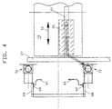
- a swivel arm 52 which is about a vertical axis of rotation 53 pivotable on the press stand 12 or the guide rail 27 or 28 is mounted.
- the swivel arm 52 is at least 90 ° from the longitudinal position shown, in the Cantilever 54 with the longitudinal direction of the guide rail 27 matches, is pivotable about a transverse direction, in the boom 54 matches the cross member 37, such as it is illustrated in Figure 4.
- the swing arm 52 can also along the Pivot axis 53 may be vertically adjustable, for which an additional Actuator serves. This has advantages, though the vertical position of the traverse 37 when changing the tool is not clearly defined.
- the arm 54 is, for example, telescopic.
- the telescopic movement can be used, the suction spider 38 (or 39) to be removed from the traverse 37.
- the then passive clutches 41, 42, 43, 44 can, for example, by a Transverse movement can be engaged and disengaged.
- the suction spiders 38, 39 with drives be provided in order to selectively along the traverse 37 moved or moved or pivoted about the cross member 37 to become.
- the drives are with the suction spiders 38, 39 changed. Alternatively, they can be part of the Traverse 37 be.
- Transport device 57 that leads to the transport and Transfer device 50 belongs.
- the transport device 57 is supported by two parallel rail guides 58, 59 formed, which, as is apparent from Figure 2, approximately The height of the swivel arm 52 extends in the horizontal direction begins and then angled in front of magazine 51 and up to the top of magazine 51, preferably up to the headpiece 14 or an overhanging one Podium 14a continues.
- On each rail guide 58, 59 is arranged a carriage or carriage 60, respectively carries a gripper 61.
- the grippers are in the pick-up position 61, as illustrated in Figure 4, with two on top of each other ends to be pointed between the press stands 12 at such a distance from each other that they are the suction spider Take over 38 (or 39) and hold between them can.
- the carriages 60 are assigned drives to the carriages 60 move along the rail guides 58, 59 can.
- the drives can be linear motors, servo motors driven belt drives or other drive means be educated.
- the grippers 61 are each trained like a crank and with a rotary or Swivel drive so that it is horizontal, be pivoted approximately in the longitudinal direction can.
- the magazine 51 arranged a number of storage spaces one above the other 62, 63, 64, 65 on, at least by the stands 12 approximately horizontally projecting supports or fingers are formed are on or on which the suction spider 38 can be discarded.
- the Suction spiders 38a, 38b, 38c are other tools and Workpieces assigned as the suction spider 38.
- the magazines 51 can be clad on the outside by means of a cover. If necessary however, they can also be left open.
- the individual recording places 62, 63, 64, 65 are each individually assigned to suction spiders 38a, 38b, 38c, 38. Markings on the suction spiders 38a, 38b, 38c, 38 such as bar code markings or other machine-readable Markers can identify the individual Make suction spider easier. You can continue to do so the grippers 61 or the storage spaces 62, 63, 64, 65 provided Readers can be provided with the Control device 45 are connected.
- the trays 62, 63, 64, 65 can, if necessary, by separate guides 71 may be formed on which grippers 72 run linearly.
- the grippers 72 are set up to to hold the respective suction spider 38 and to be moved along the guide 71. There are corresponding ones Drives provided.
- the tooling change of the press system 1 runs as follows from:
- the press system 1 is initially in the in Figure 7 illustrated state, all are suction spiders 38, 38a, 38b, 38c housed in the magazine 51.
- the Traverse 37 is empty.
- the desired tool 16 is already been moved into the press system 1.
- the lower part of the tool 18 is stored on the sliding table 19 while the upper tool part 17 is connected to the plunger 15.
- the Gripper 72 controlled so that the suction spider 38 in Direction of arrow 73 to that in the transfer position Gripper 61 is moved.
- the gripper 61 takes over the suction spider 18, after which the carriage 60 with the on it located suction spider 38 along the rail guide 57, 58 is moved vertically downwards.
- the latter is illustrated in Figure 8.
- the controller controls the carriages 60 to that Suction spider 38a, 38b or 38c, with which the traverse now 37 should be equipped.
- the transfer of the concerned Suction spider to the cross member 37 is as above described in connection with the suction spider 38. As well all other suction spiders of the transfer device 26 changed.
- a press system 1 is with a transfer device 26 provided, the workpiece-specific parts 38 through a specially designed transport and transfer facility 50 can be transported to a magazine 51.
- the Magazine 51 is preferably part of the press system 1.
Abstract
Description
Die Erfindung betrifft eine Pressenanlage, insbesondere eine Großteilstufenpresse, wie bspw. eine Karosseriepresse.The invention relates to a press system, in particular a large section press, such as a body press.
Pressenanlagen sind Einrichtungen, die über lange Zeiträume hinweg in Gebrauch bleiben, wobei sich die mit den Pressenanlagen herzustellenden Teile ändern. Bspw. bei Karosseriepressen, die zum Herstellen von Karosserieteilen dienen, sind spätestens bei einem Modellwechsel in der Pressenanlage neue Werkzeuge vorzusehen, um die geänderten Karosserieteile herstellen zu können. Zunehmend wird es jedoch außerdem erforderlich, während einer laufenden Modellreihe eine Umrüstung der Presse vorzunehmen. Bspw. kann gefordert sein, auf ein- und derselben Pressenanlage Karosserieteile unterschiedlicher Baureihen zu fertigen, die jeweils spezifische Werkzeuge erfordern. Außer den Werkzeugen sind in der Regel auch weitere Einrichtungen der Pressenanlage werkstückspezifisch. Bspw. zum Transport der Werkstücke von Arbeitsstation zu Arbeitsstation vorgesehene Transfereinrichtungen weisen Aufnahmen oder Greifer für die Werkstücke auf, die, zumindest in einigen Fällen, der Werkstückkontor angepasst sind. Solche häufig auch als Tooling bezeichneten Greifer oder Aufnahmen sind dann mit den Werkzeugen zu wechseln. Die Werkzeuge sind meist auf fahrbahren Tischen (sogenannten Schiebetischen) aus der Pressenanlage heraus und in diese hinein fahrbar. Gelegentlich sind die Schiebetische dann zusätzlich noch mit Aufnahmen für das Tooling versehen, das beim Werkzeugwechsel von der Transfereinrichtung an die Schiebetische übergeben und mit diesen aus der Presse heraus- bzw. in diese wieder hineingefahren wird.Press lines are facilities that last for a long time Remain in use for periods, with the change the parts to be manufactured in the press systems. E.g. at Body presses for the manufacture of body parts are at the latest when a model is changed in the Press machine to provide new tools to change the To be able to manufacture body parts. It is increasing however also required while a model series is in progress to convert the press. E.g. can be required on the same press system To manufacture body parts of different series, that require specific tools. Except the Tools are usually other facilities the press system, workpiece-specific. E.g. for transportation the workpieces from workstation to workstation Transfer devices have receptacles or grippers for the workpieces that, at least in some cases, the workpiece counter are adjusted. Such often are also known as tooling grippers or holders then switch with the tools. The tools are mostly on moving tables (so-called sliding tables) out of and into the press system. Occasionally, the sliding tables are additional provided with tooling receptacles for tool changing from the transfer device to the sliding tables handed over and with them out of the press or in this is driven back in.
Außerdem ist es aus der DE 19515606 A1 bekannt, an einer Transfereinrichtung vorgesehene Greifzeuge, wenn sie nicht benötigt werden, in Sammelschienen abzulegen. Die Transfereinrichtung weist zwei zueinander parallel angeordnete Führungsschienen auf, die aufeinander zu und voneinander weg sowie vertikal beweglich gelagert sind. Beide Bewegungsrichtungen werden über entsprechende Antriebe betätigt. An den Führungsschienen sind die Greifzeuge längsverschiebbar gelagert. Die Führungsschiene enthält Statoren von Linearmotoren, während die Greifzeuge dessen linear beweglichen Anker enthalten oder bilden. Im Anschluss an ein Ende der Führungsschiene ist eine Lifteinrichtung angeordnet, die mehrere kurze Aufnahmeschienenstücke trägt. Diese können bedarfsweise in direkte fluchtende Verlängerung zu der Führungsschiene überführt werden. In diesem Zustand können alle Greifzeuge, die die betreffende Führungsschiene enthält, in eine Aufnahmeschiene eingefahren werden.It is also known from DE 19515606 A1 gripping devices provided a transfer device, if they are not required to store in busbars. The Transfer device has two arranged parallel to each other Guide rails on each other towards and from each other away and vertically movable. Both Movement directions are via appropriate drives operated. The gripping devices are on the guide rails longitudinally displaceable. The guide rail contains Stators of linear motors, while the gripping devices of which contain or form linearly movable anchors. In connection at one end of the guide rail is a lifting device arranged the several short mounting rail pieces wearing. These can, if necessary, be in direct alignment Extension to be transferred to the guide rail. In this state, all gripping devices that the contains the relevant guide rail, in a receiving rail be retracted.
Diese Lösung basiert auf dem Prinzip der durch Linearmotoren bewegten Greifzeuge. Bei mechanisch bewegten Greifzeugen können sich konstruktive Schwierigkeiten ergeben. Außerdem sind die Aufnahmeschienen ein- oder ausgangsseitig der Pressenanlage anzuordnen, was insbesondere dann zu Platzproblemen führen kann, wenn als Greifzeuge Saugerbrücken zum Einsatz kommen. Außerdem müssen die Greifzeuge zur Überführung in die Aufnahmeschiene über die gesamte Länge der Führungsschiene bewegt werden. Dazu muss der entsprechende von den Greifzeugen zu durchlaufende Weg frei von Hindernissen gehalten werden.This solution is based on the principle of linear motors moving gripping devices. With mechanically moving Gryphons can experience design difficulties. In addition, the mounting rails are on the input or output side to arrange the press system, which in particular then can lead to space problems if as gripping tools Suction cups are used. They also have to Gripping tools for transfer into the mounting rail over the entire length of the guide rail can be moved. To do this the corresponding path to be followed by the gripping tools be kept clear of obstacles.
Zu dem Tooling einer Pressenanlage können auch sogenannte Ablageschablonen gehören. Sind zwischen zwei Umformstufen Zwischenablagen vorgesehen, müssen auch diese meist speziell an die zu bearbeitenden Werkstücke angepasst werden. Dies erfolgt durch an die Form der Werkstücke angepasste Schablonen, die von einem entsprechenden Träger der Zwischenablagestation gehalten und entsprechend der Werkzeugkontur ausgebildet sind. Dazu ist es aus der EP 0155332 bekannt, in einer Zwischenablage mehrere Schablonen vorzusehen, die an der Zwischenablage in Vertikalrichtung verstellbar sind. Dadurch können einzelne Schablonen in eine obere Aktivposition und andere in eine untere Passivposition überführt werden, so dass ein ausreichender Schablonensatz vorausgesetzt, eine Anpassung an unterschiedliche Werkstückkonturen durch Anheben und Absenken von einzelnen Schablonen durchgeführt werden kann.So-called tools can also be used for tooling Filing templates belong. Are between two forming stages Clipboards provided, these must also mostly specially adapted to the workpieces to be machined become. This is done by the shape of the workpieces customized stencils by a corresponding Carrier of the clipboard station held and accordingly the tool contour are formed. It is from the EP 0155332 known, several templates in a clipboard to be provided on the clipboard in the vertical direction are adjustable. This allows individual stencils in an upper active position and others in a lower one Passive position are transferred, so that a sufficient Template set provided an adjustment to different workpiece contours by raising and lowering can be carried out by individual templates.
Bei dieser Lösung sind alle möglichen Ablageschablonen in der Zwischenablagestation vorhanden.With this solution there are all possible storage templates present in the clipboard station.
Die DE 2124083 A1 offenbart eine Transferpressenlinie mit einer Transfereinrichtung, die Saugerbrücken zum Transportieren der Werkstücke aufweist. Wie die Schiebetische sind auch die Saugerbrücken seitlich aus der Transferpresse herausfahrbar. Im Bereich zwischen zwei Pressenstationen sind jeweils Pressenständer vorgesehen, zwischen denen ein Zwischenraum ausgebildet ist, durch den die Saugerbrücken durchgefahren werden können.DE 2124083 A1 discloses a transfer press line with a transfer device, the suction bridges to Transporting the workpieces. Like the sliding tables are the suction bridges from the side Transfer press can be pulled out. In the area between two Press stands are provided in each case, between which an intermediate space is formed through which the suction bridges can be run through.
Durch die erforderlichen Zwischenstände und somit Abstände zwischen den benachbarten Pressenständern benachbarter Pressenstufen ergibt sich eine vergrößerte Baulänge der Pressenanlage.Through the required intermediate status and thus Distances between the neighboring press stands Press stages result in an increased overall length the press system.
Davon ausgehend ist es Aufgabe der Erfindung, eine Pressenanlage zu schaffen, die einen verminderten Platzbedarf aufweist.Based on this, it is an object of the invention to To create press system that takes up less space having.
Diese Aufgabe wird von der Pressenanlage gemäß Anspruch 1 gelöst.This task is claimed by the press system 1 solved.
Die erfindungsgemäße Pressenanlage weist mehrere Pressenstufen auf, die hinsichtlich des Teiletransports durch eine Transfereinrichtung miteinander verknüpft sind. Die Transfereinrichtung ist dazu eingerichtet, die Werkstücke ggfs. unter zwischenzeitlichen Ablegen auf Zwischenablagen von Pressenstufe zu Pressenstufe zu transportieren. Die Transfereinrichtung weist zum Aufnehmen der Werkstücke werkstückspezifische Werkstückhaltemittel auf, die beim Werkzeugwechsel in der Regel mitzuwechseln sind. Zum Anschluss der Werkstückhaltemittel weist die Transfereinrichtung Kupplungen auf, die dazu dienen, einen feste mechanische Verbindung zwischen den Werkstückhaltemitteln und der übrigen Transfereinrichtung herzustellen. Die Kupplungen werden vorzugsweise so angeordnet, dass die wesentlichen, zur Bewirkung der Transferbewegung erforderlichen Antriebseinrichtungen an der Transfereinrichtung verbleiben, während die werkstückspezifischen Teile ausgewechselt werden. Diese können bedarfsweise noch ein oder mehrere numerisch gesteuerte Antriebseinheiten aufweisen, jedoch können sie auch vollständig passiv sein.The press system according to the invention has several Press levels on that regarding parts transport are linked together by a transfer device. The transfer device is set up to handle the workpieces if necessary with interim filing Transport clipboards from press level to press level. The transfer device has for receiving the Workpieces workpiece-specific workpiece holding means, which are usually to be changed when changing tools. The transfer device points to the connection of the workpiece holding means Couplings that serve to secure a mechanical connection between the workpiece holding means and the rest of the transfer device. The Couplings are preferably arranged so that the essential to effect the transfer movement Drive devices on the transfer device remain while the workpiece-specific parts are replaced become. If necessary, these can still be a or have several numerically controlled drive units, however, they can also be completely passive.
Jeder Kupplung sind mehrere Werkstückhaltemittel zugeordnet, die ihrerseits wiederum unterschiedlichen Werkstücken zugeordnet sind. Die Werkstückhaltemittel bilden eine zusammengehörige Gruppe oder einen Satz, wobei dieser Satz für jeden Werkstücktyp mindestes ein geeignetes Werkstückhaltemittel enthält. Dies ist insbesondere bei Anwendungen von Vorteil, bei denen mehrere fest eingerichtete Produktlinien oder Produkte nacheinander auf der genannten Pressenanlage zu produzieren sind. Einzelne Elemente des Satzes können bedarfsweise ausgewechselt, ergänzt oder angepasst werden.Several workpiece holding devices are assigned to each coupling, which in turn are different workpieces assigned. Form the workpiece holding means a related group or sentence, this one Set at least one suitable workpiece holder for each workpiece type contains. This is especially true for applications advantageous where several fixed Product lines or products one after the other on the above Press system are to be produced. Individual elements of the If necessary, the sentence can be replaced, supplemented or be adjusted.
An der Pressenanlage ist eine Steuereinrichtung vorgesehen, die eine Transport- und Übergabeeinrichtung steuert. Letztere dient dazu, die Werkstückhaltemittel automatisch aus ihrer Betriebsposition in der Pressenanlage in das Magazin zu überführen. Dabei wird das Werkstückhaltemittel von der Transfereinrichtung gelöst, indem die Kupplungen geöffnet werden, das Werkstückhaltemittel zu dem Magazin verfahren und dort abgelegt wird. Nachdem der gesamte Vorgang unter Kontrolle der Steuereinrichtung abläuft, kann auf manuelle Umrüstung des Toolings, d.h. der Werkstückhaltemittel verzichtet werden. Dies kann einen erheblichen Kostenvorteil mit sich bringen.A control device is provided on the press system, which controls a transport and transfer device. The latter is used to automatically hold the workpiece from their operating position in the press line in to transfer the magazine. The workpiece holding device released from the transfer device by the couplings be opened, the workpiece holder to the Move the magazine and place it there. After the whole Process under control of the control device, can be changed to manual tooling, i.e. the Workpiece holding means are dispensed with. This can be one bring considerable cost advantage.
Außerdem kann auf mechanische Aufnahmen zur Lagerung der Werkstückhaltemittel an den Schiebetischen beim Werkzeugwechsel verzichtet werden. Dadurch können Beschädigungen dieser Aufnahmen und evtl. schon auf den Aufnahmen befindlicher Werkstückhaltemittel beim Rüstvorgang vermieden werden. Die zum Teil relativ filigranen Werkstückhaltemittel können automatisch in geschützte Positionen, d.h. in ihre Magazine verfahren werden.You can also use mechanical shots for storage the workpiece holding device on the sliding tables when changing tools to be dispensed with. This can cause damage of these recordings and possibly already on the recordings existing workpiece holding means avoided during the setup process become. The partially filigree workpiece holding devices can automatically move into protected positions, i.e. get into their magazines.
Der Grundgedanke, an der Pressenanlage möglichst in ansonsten nicht genutzten Räumen Magazine zur Aufnahme der Werkstückhaltemittel vorzusehen und die Werkstückhaltemittel mittels einer von einer Steuereinrichtung kontrollierten Transport- und Übergabeeinrichtung in dieses Magazin oder diese Magazine zu überführen, ermöglicht eine wesentliche Platzreduktion beim Aufbau von Pressenanlagen. Die Werkstückhaltemittel müssen nun nicht mehr außerhalb der Pressenanlage gelagert werden. Ansonsten erforderlicher zusätzlicher Raumbedarf der vom Pressenbetreiber aufzubringen wäre, entfällt somit. Außerdem ermöglicht das von den Schiebetischen unabhängige Herausfahren der Werkstückhaltermittel (Saugerbrücken oder Saugerspinnen) aus den Pressestufen eine schmalere Gestaltung der Schiebetische und somit einen geringeren Ständerabstand. Die Gesamtlänge der Presse kann so reduziert werden.The basic idea of using the press system as possible otherwise unused rooms magazines to record the To provide workpiece holding means and the workpiece holding means by means of a controlled by a control device Transport and transfer device in this magazine or transferring these magazines enables one Significant space reduction when building press systems. The workpiece holding means no longer have to be outside the press system. Otherwise required additional space required by the press operator would be eliminated. It also enables the workpiece holder means move out independently of the sliding tables (Suction bridges or suction spiders) the press stages a narrower design of the sliding tables and therefore a smaller stand spacing. The total length the press can be reduced.
Ein weiterer Vorteil ist der Wegfall der ansonsten manuellen Be- und Entladevorgänge zum Bestücken des Schiebetischs mit Werkstückhaltemitteln. Darüber hinaus ist es möglich, Werkstückhaltemittel rechnergesteuert am CAD einzustellen und die Feineinstellung in der Pressenanlage selbst vorzunehmen, so dass Personal eingespart werden kann.Another benefit is the elimination of the otherwise manual loading and unloading processes for loading the sliding table with workpiece holding means. Beyond that it is possible to set workpiece holding devices computer-controlled on the CAD and the fine adjustment in the press system yourself, so that personnel are saved can.
Der vollautomatische Be- und Entladevorgang sowie die geschützte Unterbringung des Toolings bzw. der Werkstückhaltemittel in einem Magazin, erzielen eine Personalunabhängigkeit. Die Zuordnung des Magazins zu der Pressenanlage und die Personalunabhängigkeit schützen das Tooling (die Werkstückhaltemittel) und die Toolingaufnahmen von ungewollter Beschädigung.The fully automatic loading and unloading process as well as the Protected storage of tooling or workpiece holding devices in a magazine, achieve staff independence. The assignment of the magazine to the press system and staff independence protect tooling (the workpiece holding means) and the tooling recordings of unwanted damage.
Die kompakte Anordnung des Magazins oder Magazine an der Presse erspart dem Pressenbetreiber, wie erwähnt, eine zusätzliche Lagereinrichtung für das Tooling, wodurch sich der für den Betrieb der Pressenanlage erforderliche Platzbedarf verringert.The compact arrangement of the magazine or magazines the press saves the press operator one, as mentioned additional storage facility for the tooling, which makes the space required to operate the press system decreased.
Die Pressenanlage kann mit einem einzigen Magazin versehen sein. Vorzugsweise sind jedoch mehrere vorgesehen. Die Magazine können von den Pressenständern getragen sein. Ein zweckmäßiger unterbringungsort ist unterhalb der Kopfstücke. Andere Anordnungen sind möglich.The press system can be operated with a single magazine be provided. However, several are preferably provided. The magazines can be carried by the press stands his. A convenient location is below Head pieces. Other arrangements are possible.
Die Magazine oder das Magazin sind bzw. ist vorzugsweise an einer solchen Stelle angeordnet, dass es das Ausfahren des Schiebetischs aus der Pressenanlage nicht behindert. Das Magazin ist bei einer bevorzugten Ausführungsform der Pressenanlage außerhalb des Ausfahrfensters zum Ausfahren des Werkzeugs aus der Pressenanlage angeordnet. Bspw. kann es oberhalb desselben angeordnet, z.B. an den Pressenständern sein, so dass das Werkzeug und der Schiebetisch unter dem Magazin durchfahrbar sind. Das Magazin oder die Magazine können auch unter den Tischen angeordnet werden.The magazines or the magazine are or are preferred arranged in such a place that it is extending the sliding table from the press system is not hindered. The magazine is in a preferred embodiment the press system outside the exit window for moving the tool out of the press system arranged. E.g. it can be placed above it e.g. be on the press stands so that the tool and the sliding table can be passed under the magazine. The Magazine or magazines can also be placed under the tables to be ordered.
Die Transfereinrichtung ist vorzugsweise als Zweiachstransfereinrichtung ausgebildet, die Laufschienen zur Führung von Lauf wagen aufweist. Die Laufwagen sind vorzugsweise in zwei oder mehr Laufwagengruppen unterteilt, wobei die Laufwagen einer Gruppe jeweils synchron zueinander bewegt werden. Sie können bspw. über Schubstangen miteinander verbunden sein, um von einer gemeinsamen Antriebsquelle her angetrieben zu werden. Zwischen den Laufwagen können Traversen gehalten sein, die das Werkstückhaltemittel bilden oder Werkstückhaltemittel tragen. Bspw. können auf den Traversen Saugerspinnen angeordnet sein, wobei die Kupplungen zwischen den Saugerspinnen und den Traversen wirkend angeordnet sind. In diesem Fall werden von der Transport- und Übergabeeinrichtung lediglich die Saugerspinnen in die Magazine überführt, während die Traversen in der Transfereinrichtung verbleiben. Alternativ können auch die Traversen mit den Saugerspinnen ausgewechselt werden. Die Kupplungen sind dann zwischen den Laufwagen und den Traversen angeordnet.The transfer device is preferably a two-axis transfer device trained the rails for Carriage management. The carriages are preferred divided into two or more carriage groups, where the carriages of a group are synchronous to each other be moved. For example, you can use push rods connected to each other from a common drive source to be driven here. Between the carriages can be held trusses that the workpiece holding means form or carry workpiece holding means. E.g. suction spiders can be arranged on the traverses, the couplings between the suction spiders and the Trusses are arranged to act. In this case from the transport and transfer facility only that Suction spiders transferred to the magazines while the trusses remain in the transfer facility. Alternatively the trusses can also be replaced with the suction spiders become. The couplings are then between the carriages and arranged the trusses.
Die Ablagebewegung der Saugerspinne bzw. des sonstigen Werkstückhaltemittels findet auf einer Bahn statt, die von der übrigen Transfereinrichtung nicht durchlaufbar ist. Die Übergabe und Transporteinrichtung übernimmt deshalb den Transport der Werkstückhaltemittel auf dieser Bahn.The storage movement of the suction spider or the other Workpiece holding means takes place on a path, that cannot be run through by the rest of the transfer device is. The handover and transport equipment therefore takes over the transport of the workpiece holder on this Train.
Zu der Transport- und Übergabeeinrichtung gehört bei einer Ausführungsform eine Schwenkeinheit mit einem um eine vertikale Schwenkachse schwenkbaren Ausleger. Dieser dient dazu, das Werkstückhaltemittel aus seiner Gebrauchslage in eine Speicherlage zu schwenken, die sich von der Gebrauchslage unterscheidet. Dadurch können in Gebrauch bspw. quer orientierte Saugerspinnen in Längsrichtung geschwenkt werden, um so besonders platzsparend in seitlich an den Presse angeordneten Magazinen zwischengelagert zu werden.Belongs to the transport and handover facility one embodiment, a swivel unit with a a vertical swivel axis swiveling boom. This is used to remove the workpiece holder from its position of use to pivot into a storage location, which is different from the Use situation differs. This can be used For example, transversely oriented suction spiders pivoted in the longitudinal direction become all the more space-saving in sideways magazines arranged on the press temporarily stored become.
Ein Transportlift zur Bewegung der Werkstückhaltemittel auf vorgegebener Bahn zwischen dem Magazin und der Transfereinrichtung weist vorzugsweise einen Antrieb auf, der in mehreren Übergabepositionen gezielt anhaltbar ist. Der Antrieb kann ortsfest gelagert und kraftübertragend mit dem Aufnahmemittel verbunden sein oder direkt an dem Aufnahmemittel vorgesehen sein.A transport lift for moving the workpiece holder on a predefined path between the magazine and the The transfer device preferably has a drive, which can be stopped in several transfer positions. The drive can be mounted in a stationary position and transmits power be connected to the receiving means or directly on the Recording means may be provided.
Bei einer bevorzugten Ausführungsform sind in den Magazinen so viel Ablageplätze vorhanden, wie unterschiedliche Werkstückhaltemittel. Dadurch können bedarfsweise alle Werkstückhaltemittel aus der Pressenanlage, d.h. aus der Transfereinrichtung entfernt werden, so dass der Arbeitsbereich der Presse in einem Ruhezustand vollständig geräumt ist.In a preferred embodiment are in the Magazines have as many storage spaces as there are different ones Workpiece holding means. This can, if necessary all workpiece holding devices from the press system, i.e. out the transfer device to be removed, leaving the work area the press completely in an idle state is cleared.
Die Magazine weisen Ablagepositionen auf, die den Werkstückhaltemitteln vorzugsweise individuell zugeordnet sind. Die Zuordnung kann dabei bspw. schon dadurch vorgenommen werden, dass die Steuereinrichtung für jeden Ablageplatz ein bestimmtes Werkstückhaltemittel vorsieht. Alternativ können an den Werkstückhaltemitteln und/oder an den Ablageplätzen maschinenlesbare Markierungen vorgesehen sein, die ein bspw. an der Transport- und Übergabeeinrichtung vorgesehener Lesekopf erfasst. Die Steuereinrichtung kann dann das entsprechende Werkstückhaltemittel auf den für es vorgesehenen Platz in dem Magazin bringen. Alternativ können auch an den Aufnahmeplätzen Lesemittel vorgesehen sein, die Markierungen der Werkstückhaltemittel lesen und/oder anderweitig erfassen.The magazines have storage positions that the Workpiece holding means preferably assigned individually are. The assignment can already be made in this way, for example that the control device for each storage space provides a specific workpiece holding means. Alternatively, on the workpiece holding means and / or on machine-readable markings are provided for the storage spaces be, for example, at the transport and transfer facility provided read head detected. The control device can then the corresponding workpiece holder on the place it in the magazine. Alternatively reading means can also be provided at the recording locations be, read the marks of the workpiece holding means and / or capture otherwise.
Weitere Einzelheiten vorteilhafter Ausführungsformen und Weiterbildungen der Erfindung sind aus der Zeichnung oder der zugehörigen Beschreibung zu entnehmen und/oder Gegenstand von Unteransprüchen.Further details of advantageous embodiments and further developments of the invention are from the drawing or from the associated description and / or Subject of subclaims.
In der Zeichnung ist ein Ausführungsbeispiel der Erfindung
veranschaulicht. Es zeigen:
In Figur 1 ist eine Pressenanlage 1 veranschaulicht,
die mehrere Pressenstationen 2, 3, 4, 5, 6 aufweist. Die
Pressenstationen 2, 3, 4, 5, 6 sind untereinander im Wesentlichen
gleich ausgebildet, so dass die nachfolgende
Beschreibung einer Pressenstation stellvertretend für alle
steht. Gewisse Abweichungen können hinsichtlich der Pressenstation
2 vorhanden sein, die als Ziehstufe ausgebildet
sein kann. Die übrigen Pressenstationen 3, 4, 5, 6 sind
Umformstufen, wobei bedarfsweise auch Nachziehstufen vorgesehen
sein können.A press system 1 is illustrated in FIG. 1,
which has
Zu der Pressenstation 2 gehört ein Pressentisch 11,
auf dem Pressenständer 12 stehen, die wiederum ein Kopfstück
14 tragen. Das Kopfstück 14 weist einen Antrieb für
einen unter dem Kopfstück 14 hängenden Stößel 15 auf, der
durch den Antrieb vertikal auf und ab bewegbar ist. Der
Stößel 15 trägt einen zu einem Werkzeug 16 gehörigen Werkzeugteil
17. Ein unterer Werkzeugteil 18, der ebenfalls zu
dem Werkzeugteil 16 gehört, lagert dabei auf einem Schiebetisch
19, der auf dem Pressentisch 11 steht und auf
Schienen 21 seitlich zwischen Pressenständern 12 hindurch
aus der Pressenstation 2 ausfahrbar ist. Neben der Pressenanlage
1 stehen weitere Schiebetische 22, mit darauf
gelagerten Werkezeugen 23 bereit, um bedarfsweise von der
Seite her in die Pressenanlage eingefahren werden zu können.A press table 11 belongs to the
Die Pressenanlage 1 weist zwischen den einzelnen
Pressenstufen 2, 3, 4, 5, 6 Zwischenablagen 24 auf, auf
denen die Werkstücke, bspw. Blechteile auf ihrem Weg von
Pressenstufe zu Pressenstufe kurzzeitig abgelegt werden
können. The press system 1 points between the individual
Press stages 2, 3, 4, 5, 6
Die Pressenanlage 1 weist für den Werkstücktransport
von Pressenstation zu Pressenstation, d.h. im Einzelnen
von einem Werkzeug zu einer nachfolgenden Zwischenablage
und dann zu dem nächsten Werkzeug eine Transfereinrichtung
26 auf, die insbesondere aus Figur 2 hervorgeht. Zu der
Transfereinrichtung 26 gehören zwei zu beiden Seiten der
Werkzeuge 16 angeordnete Führungsschienen 27, 28, die
durch nicht weiter veranschaulichte Mittel in der Höhe
verfahrbar gehalten sind. Auf den sich horizontal erstreckenden
Führungsschienen 27, 28 die bspw. über Hubeinheiten
an den Pressenständern 12 gelagert sind, sind Laufwagen
31, 32 längsverschiebbar gelagert. Die von den Führungsschienen
27, 28 geführten Laufwagen werden z.B. durch
Schubstangen 33, 34 angetrieben, die zu einer entsprechenden
Transferantriebseinrichtung führen. Mit den Schubstangen
33, 34 können weitere Laufwagen verbunden sein,
die synchron mit den Laufwagen 31, 32 zu bewegen sind.
Weitere Schubstangen 35, 36 können eine weitere Wagengruppe
relativ unabhängig von Bewegungen der ersten Wagengruppe
bewegen.The press system 1 has for the workpiece transport
from press station to press station, i.e. in detail
from a tool to a subsequent clipboard
and then a transfer device to the
Die beiden einander gegenüberliegenden Laufwagen 31,
32 halten zwischeneinander eine Traverse 37, an der zwei
Saugerspinnen 38, 39 gehalten sind. Die Traverse 37 ist
bspw. ein Kastenprofilträgerelement, das mit seinen Enden
fest, bedarfsweise aber auch lösbar mit den Laufwagen 31,
32 verbunden sein kann. Zur Halterung der Saugerspinnen
38, 39 an der Traverse 37 dienen Kupplungen 41, 42, 43,
44, die entweder kraftbetätigt oder durch eine gezielte
Relativbewegung zwischen der jeweiligen Saugerspinne 38,
39 und der Traverse 37 ein- und auskuppelbar sind. Sind
die Kupplungen 41, 42, 43, 44 kraftbetätigt, sind sie der
Steuerung einer Steuereinrichtung 45 unterstellt, die über
nicht weiter veranschaulichte elektrische, pneumatische
oder hydraulische Signalleitungen die Kupplungen 41 bis 44
betätigt.The two
Die Saugerspinnen 38, 39 sind werkstückspezifisch
ausgebildet. Die Positionen einzelner Sauger 46, 47 hängen
von der Kontur der zu transportieren Blechteile ab. Um die
Saugerspinnen 38, 39, die als Werkstückhaltemittel dienen,
bedarfsweise wechseln zu können, ist wenigstens zu einer,
vorzugsweise jedoch zu beiden Seiten des Werkzeugs 16 jeweils
eine Transport- und Übergabeeinrichtung 50 angeordnet,
die dazu dient, die Saugerspinnen 38, 39 in ein Magazin
51 zu überführen. Wie aus Figur 2 ersichtlich, sind
die Transport- und Übergabeeinrichtungen 50 und die Magazine
51 zueinander spiegelsymmetrisch aufgebaut, so dass
sich die nachfolgende Beschreibung gleichermaßen sowohl
auf die rechtsseitige wie auf die linksseitigen Transport- und
Übergabeeinrichtung und die Magazine bezieht.The
Zu der Transport- und Übergabeeinrichtung 50 gehört
ein Schwenkarm 52, der um eine vertikale Drehachse 53
schwenkbar an dem Pressenständer 12 oder der Führungsschiene
27 bzw. 28 gelagert ist. Erstgenannte Variante
geht aus Figur 3 hervor. Der Schwenkarm 52 ist um wenigstens
90° aus der dargestellten Längsposition, in der sein
Ausleger 54 mit der Längsrichtung der Führungsschiene 27
übereinstimmt, über eine Querrichtung schwenkbar ist, in
der der Ausleger 54 mit der Traverse 37 übereinstimmt, wie
es in Figur 4 veranschaulicht ist. Zur Verschwenkung dient
ein symbolisch veranschaulichter Schwenkantrieb 55. Bedarfsweise
kann der Schwenkarm 52 außerdem entlang der
Schwenkachse 53 vertikal verstellbar sein, wozu ein zusätzlicher
Verstellantrieb dient. Dies hat Vorteile, wenn
die Vertikalposition der Traverse 37 bei Werkzeugwechsel
nicht eindeutig festgelegt ist.Belongs to the transport and transfer device 50
a
Der Ausleger 54 ist bspw. teleskopierbar ausgebildet.
Die Teleskopbewegung kann dazu genutzt werden, die Saugerspinne
38 (bzw. 39) von der Traverse 37 zu lösen. Die dann
passiven Kupplungen 41, 42, 43, 44 können bspw. durch eine
Querbewegung ein- und auskuppelbar sein.The
Alternativ können die Saugerspinnen 38, 39 mit Antrieben
versehen sein, um gezielt entlang der Traverse 37
verschoben bzw. verfahren oder um die Traverse 37 geschwenkt
zu werden. Die Antriebe werden mit den Saugerspinnen
38, 39 gewechselt. Alternativ können sie Teil der
Traverse 37 sein.Alternatively, the
Aus den Figuren 3 und 4 geht außerdem eine weitere
Transporteinrichtung 57 hervor, die zu der Transport- und
Übergabeeinrichtung 50 gehört. Die Transporteinrichtung 57
wird durch zwei zueinander parallele Schienenführungen 58,
59 gebildet, die, wie aus Figur 2 hervorgeht, etwa auf
Höhe des Schwenkarms 52 sich in Horizontalrichtung erstreckend
beginnt und dann vor dem Magazin 51 abgewinkelt und
sich bis zu dem oberen Rand des Magazins 51 nach oben,
vorzugsweise bis zu dem Kopfstück 14 oder einem überhängenden
Podest 14a fortsetzt. Auf jeder Schienenführung 58,
59 ist jeweils ein Schlitten oder Wagen 60 angeordnet, der
einen Greifer 61 trägt. In Abholposition stehen die Greifer
61, wie in Figur 4 veranschaulicht, mit zwei aufeinander
zu weisenden Enden zwischen den Pressenständern 12
in einem solchen Abstand voneinander, dass sie die Saugerspinne
38 (bzw. 39) übernehmen und zwischeneinander halten
können. Den Wagen 60 sind Antriebe zugeordnet, um die Wagen
60 entlang der Schienenführungen 58, 59 verfahren zu
können. Die Antriebe können durch Linearmotoren, über Servomotoren
getriebene Riementriebe oder anderweitige Antriebsmittel
gebildet sein. Die Greifer 61 sind jeweils
nach Art einer Kurbel ausgebildet und mit einem Dreh- oder
Schwenkantrieb versehen, so dass sie um eine horizontale,
etwa in Längsrichtung ausgerichtete Achse geschwenkt werden
können.Another is shown in FIGS. 3 and 4
Wie aus Figur 2 oder auch Figur 5 ersichtlich, weist
das Magazin 51 übereinander angeordnet mehrere Ablageplätze
62, 63, 64, 65 auf, die wenigstens durch von den Ständern
12 etwa horizontal wegragende Träger oder Finger gebildet
sind, auf oder an denen sich die Saugerspinne 38
ablegen lässt. In dem so gebildeten Magazin 51 sind Saugerspinnen
38a, 38b, 38c auf den Ablageplätzen 62, 63, 64
angeordnet und können bei Bedarf abgeholt und anstelle der
Saugerspinne 38 an der Traverse 37 befestigt werden. Die
Saugerspinnen 38a, 38b, 38c sind anderen Werkzeugen und
Werkstücken zugeordnet, als die Saugerspinne 38.As can be seen from FIG. 2 or also FIG. 5,
the
Wie Figur 1 andeutet, können die Magazine 51 nach
außen hin mittels einer Abdeckung verkleidet sein. Bedarfsweise
können sie jedoch auch offen gelassen werden.As indicated in Figure 1, the
Den einzelnen Aufnahmeplätzen 62, 63, 64, 65 sind
jeweils Saugerspinnen 38a, 38b, 38c, 38 individuell zugeordnet.
Markierungen an den Saugerspinnen 38a, 38b, 38c,
38 wie bspw. Barcodemarkierungen oder anderweitige maschinenlesbare
Markierungen können die Identifikation der einzelnen
Saugerspinnen erleichtern. Weiter können dazu an
den Greifern 61 oder den Ablageplätzen 62, 63, 64, 65 vorgesehenen
Leseeinrichtungen vorgesehen sein, die mit der
Steuereinrichtung 45 verbunden sind.The individual recording places 62, 63, 64, 65 are
each individually assigned to
Die Ablagen 62, 63, 64, 65 können bedarfsweise durch
separate Führungen 71 gebildet sein, auf denen Greifer 72
linear verschiebbar laufen. Die Greifer 72 sind dazu eingerichtet,
die jeweilige Saugerspinne 38 zu halten und
entlang der Führung 71 verfahren zu werden. Dazu sind entsprechende
Antriebe vorgesehen.The
Der Toolingwechsel der Pressenanlage 1 läuft folgendermaßen ab:The tooling change of the press system 1 runs as follows from:
Befindet sich die Pressenanlage 1 zunächst in dem in
Figur 7 veranschaulichten Zustand, sind alle Saugerspinnen
38, 38a, 38b, 38c in dem Magazin 51 untergebracht. Die
Traverse 37 ist leer. Das gewünschte Werkzeug 16 ist bereits
in die Pressenanlage 1 eingefahren worden. Das Werkzeugunterteil
18 lagert auf dem Schiebetisch 19, während
das Werkzeugoberteil 17 mit dem Stößel 15 verbunden ist.
Es ist nun noch die Saugerspinne 38 zu der Traverse 37 zu
transportieren und mit dieser zu verbinden. Dazu wird der
Greifer 72 angesteuert, so dass die Saugerspinne 38 in
Richtung des Pfeils 73 zu dem in Übergabeposition befindlichen
Greifer 61 verfahren wird. Der Greifer 61 übernimmt
die Saugerspinne 18, wonach der Laufwagen 60 mit der darauf
befindlichen Saugerspinne 38 entlang der Schienenführung
57, 58 vertikal nach unten verfahren wird. Letzteres
ist in Figur 8 veranschaulicht. Durch den an der Schienenführung
57 vorhandenen Bogen schwenkt dabei die Saugerspinne
38 zwangsläufig von ihrer im Magazin 51 eingenommenen
Vertikalposition in ihre Horizontalposition. Ist der
Laufwagen 60 mit der Saugerspinne 38 an dem unteren ständerseitigen
Ende der Schienenführungen 57, 58 angekommen,
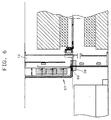
befindet sich die Sauerspinne 38, wie in Figur 6 veranschaulicht,
zwischen den Ständern 12. Der Schwenkarm 52
steht dabei in der Figur 3 veranschaulichten Übernahmeposition
zwischen den Pressenständern 12. Hier übergeben die
Greifer 61 die Saugerspinne 38 an den Ausleger 54. Dieser
schwenkt nun aus der Position gemäß Figur 3 in die Position
gemäß Figur 4, so dass die Saugerspinne 38 an die Traverse
37 herangefahren wird. Durch eine geeignete Verschiebung
in Richtung der Traverse 37 (Verschiebungsrichtung
ist in Figur 4 mit einem Pfeil 74 bezeichnet) können
die Kupplungen 41, 42 geschlossen und die Saugerspinne 38
somit an die Traverse 37 angekoppelt werden.The press system 1 is initially in the in
Figure 7 illustrated state, all are
Zum erneuten Werkzeugwechsel wird der vorab geschilderte
Ablauf zum Überführen einer Saugerspinne 38 aus dem
Magazin 51 zu der Traverse 37 umgekehrt durchlaufen. Dabei
sucht die Steuereinrichtung 45 zum Ablegen der Saugerspinne
38 in dem Magazin 51 einen freien Ablageplatz 62, 63,
64, 65. Eine einfache Möglichkeit dazu ist, wenn die Steuereinrichtung
die Ablageplatzbelegung in dem Magazin 51
speichert und auf diese Weise ohne Prüfung vor Ort über
Information über die Magazinbelegung verfügt. Alternativ
kann die Ablageplatzbelegung mit entsprechenden Sensoren
erfasst werden. Außerdem ist es möglich, mit an den Greifern
61 oder den Laufwagen 60 vorgesehenen Sensoren eine
an der Greiferspinne 38 angebrachte Saugerspinnenkennung
zu erfassen und mit einer Ablageplatzkennung abzugleichen.
Dadurch kann eine bestimmte Saugerspinne 38 immer wieder
an einem ihr allein zugeordneten Ablageplatz 65 abgelegt
werden. Entsprechendes gilt für die anderen Saugerspinnen
und Ablageplätze. To change the tool again, the one described above is used
Sequence for transferring a
Ist die Saugerspinne 38 in das Magazin 51 gefahren,
steuert die Steuereinrichtung die Laufwagen 60 zu derjenigen
Saugerspinne 38a, 38b oder 38c, mit der nun die Traverse
37 bestückt werden soll. Die Überführung der betreffenden
Saugerspinne zu der Traverse 37 erfolgt, wie oben
im Zusammenhang mit der Saugerspinne 38 beschrieben. Ebenso
werden alle anderen Saugerspinnen der Transfereinrichtung
26 gewechselt.If the
Eine Pressenanlage 1 ist mit einer Transfereinrichtung
26 versehen, deren werkstückspezifischen Teile 38
durch eine eigens vorgesehene Transport- und Übergabeeinrichtung
50 zu einem Magazin 51 transportierbar sind. Das
Magazin 51 ist vorzugsweise Bestandteil der Pressenanlage
1.A press system 1 is with a
Claims (17)
Applications Claiming Priority (2)
| Application Number | Priority Date | Filing Date | Title |
|---|---|---|---|
| DE19927824 | 1999-06-18 | ||
| DE1999127824 DE19927824A1 (en) | 1999-06-18 | 1999-06-18 | Press system with automatic tool change |
Publications (2)
| Publication Number | Publication Date |
|---|---|
| EP1063031A2 true EP1063031A2 (en) | 2000-12-27 |
| EP1063031A3 EP1063031A3 (en) | 2002-06-19 |
Family
ID=7911670
Family Applications (1)
| Application Number | Title | Priority Date | Filing Date |
|---|---|---|---|
| EP00112557A Withdrawn EP1063031A3 (en) | 1999-06-18 | 2000-06-14 | Press arrangement with automatic tool changing |
Country Status (3)
| Country | Link |
|---|---|
| EP (1) | EP1063031A3 (en) |
| BR (1) | BR0004012A (en) |
| DE (1) | DE19927824A1 (en) |
Cited By (3)
| Publication number | Priority date | Publication date | Assignee | Title |
|---|---|---|---|---|
| CN104353753A (en) * | 2014-11-11 | 2015-02-18 | 营口锻压机床有限责任公司 | Automotive filter casing drawing machine |
| CN114345994A (en) * | 2021-12-30 | 2022-04-15 | 福建省金瑞高科有限公司 | Multifunctional full-automatic infrared induction plane shaping equipment |
| CN114345994B (en) * | 2021-12-30 | 2024-04-19 | 福建省金瑞高科有限公司 | Multifunctional full-automatic infrared induction plane shaping equipment |
Families Citing this family (2)
| Publication number | Priority date | Publication date | Assignee | Title |
|---|---|---|---|---|
| DE102006050648B3 (en) * | 2006-10-24 | 2008-02-07 | Wilfried Strothmann Gmbh Maschinenbau- Und Handhabungstechnik | Device turning over sheet components between two presses and exchanging gripping tools, includes carriers with arms and clamping mechanisms running on elevated beam |
| CN107840156A (en) * | 2017-11-20 | 2018-03-27 | 海安交睿机器人科技有限公司 | Automatic laminating device |
Citations (6)
| Publication number | Priority date | Publication date | Assignee | Title |
|---|---|---|---|---|
| DE3246096A1 (en) * | 1981-12-15 | 1983-07-21 | Komatsu Mfg Co Ltd | Transfer device for presses |
| DE4124083A1 (en) * | 1991-07-19 | 1993-01-21 | Erfurt Umformtechnik Gmbh | TRANSFER PRESS LINE |
| DE19515606A1 (en) * | 1995-04-28 | 1996-10-31 | Schuler Pressen Gmbh & Co | Appts. for storing material to be passed through press or other similar machine |
| EP0773078A1 (en) * | 1995-11-13 | 1997-05-14 | SCHULER PRESSEN GmbH & Co. | Convertible multistage press |
| EP0878251A1 (en) * | 1997-05-16 | 1998-11-18 | SCHULER PRESSEN GmbH & Co. | Transfer press with a laterally located support on a moving bolster for workpiece-holders |
| EP0879659A2 (en) * | 1997-05-23 | 1998-11-25 | SCHULER PRESSEN GmbH & Co. | Press installations with automatic tool change and method of tool change |
-
1999
- 1999-06-18 DE DE1999127824 patent/DE19927824A1/en not_active Withdrawn
-
2000
- 2000-06-14 EP EP00112557A patent/EP1063031A3/en not_active Withdrawn
- 2000-06-19 BR BR0004012-6A patent/BR0004012A/en not_active Application Discontinuation
Patent Citations (6)
| Publication number | Priority date | Publication date | Assignee | Title |
|---|---|---|---|---|
| DE3246096A1 (en) * | 1981-12-15 | 1983-07-21 | Komatsu Mfg Co Ltd | Transfer device for presses |
| DE4124083A1 (en) * | 1991-07-19 | 1993-01-21 | Erfurt Umformtechnik Gmbh | TRANSFER PRESS LINE |
| DE19515606A1 (en) * | 1995-04-28 | 1996-10-31 | Schuler Pressen Gmbh & Co | Appts. for storing material to be passed through press or other similar machine |
| EP0773078A1 (en) * | 1995-11-13 | 1997-05-14 | SCHULER PRESSEN GmbH & Co. | Convertible multistage press |
| EP0878251A1 (en) * | 1997-05-16 | 1998-11-18 | SCHULER PRESSEN GmbH & Co. | Transfer press with a laterally located support on a moving bolster for workpiece-holders |
| EP0879659A2 (en) * | 1997-05-23 | 1998-11-25 | SCHULER PRESSEN GmbH & Co. | Press installations with automatic tool change and method of tool change |
Cited By (4)
| Publication number | Priority date | Publication date | Assignee | Title |
|---|---|---|---|---|
| CN104353753A (en) * | 2014-11-11 | 2015-02-18 | 营口锻压机床有限责任公司 | Automotive filter casing drawing machine |
| CN104353753B (en) * | 2014-11-11 | 2018-04-06 | 营口锻压机床有限责任公司 | Automobile filter housing stretching-machine |
| CN114345994A (en) * | 2021-12-30 | 2022-04-15 | 福建省金瑞高科有限公司 | Multifunctional full-automatic infrared induction plane shaping equipment |
| CN114345994B (en) * | 2021-12-30 | 2024-04-19 | 福建省金瑞高科有限公司 | Multifunctional full-automatic infrared induction plane shaping equipment |
Also Published As
| Publication number | Publication date |
|---|---|
| BR0004012A (en) | 2001-07-24 |
| DE19927824A1 (en) | 2000-12-21 |
| EP1063031A3 (en) | 2002-06-19 |
Similar Documents
| Publication | Publication Date | Title |
|---|---|---|
| DE102011015741B4 (en) | Umrüstverfahren | |
| AT304359B (en) | Mechanical transport trolley | |
| EP3463708B1 (en) | Tool storage system, production plant and method for manipulating with such a tool storage system | |
| EP3242755B1 (en) | Feeding device for a bending press and method for feeding a bending press | |
| DE102008017788A1 (en) | Device for transporting and picking up workpiece plates and method for transporting and picking up workpiece plates | |
| EP2724797B1 (en) | Tool holder for tools of a machine tool, machine assembly with such a tool holder and method for managing tools with such a mechanical assembly | |
| WO2006063541A1 (en) | Work cell for assembling units of workpieces on pallets and method for operating the same | |
| EP3579987B1 (en) | Bending tool storage device and method for feeding a press brake | |
| EP0671228A2 (en) | Transporting equipment for work pieces in a press | |
| DE4225248A1 (en) | Blank feeder for a press | |
| EP0901848B1 (en) | Transfer presses with automatic tool change | |
| DE102013223252B4 (en) | A workpiece transfer machine and machine unloading apparatus and machine assembly for processing workpieces with such a workpiece transfer apparatus | |
| EP2692455B1 (en) | Tool machine for processing sheet-shaped workpieces, in particular sheet metal | |
| DE102020001963B4 (en) | Manufacturing cell with workpiece return and operating procedures for this | |
| DE19925343A1 (en) | Transfer facility | |
| AT503648B1 (en) | Work station including at least one clamping frame at its side for positioning, holding and/or connecting number of components useful for production of vehicle bodies facilitates changing of workpiece type | |
| DE102004046176A1 (en) | Facility for automated storage of nonsorted goods comprises a shelves unit and a transfer unit with at least two transfer platforms movable between a transfer zone and at least one withdrawal zone | |
| EP0879659A2 (en) | Press installations with automatic tool change and method of tool change | |
| DE19756278B4 (en) | Machine system for processing cubic workpieces in particular | |
| EP1063031A2 (en) | Press arrangement with automatic tool changing | |
| EP0150662B1 (en) | Apparatus for loading and unloading machines for working on printed circuit boards, especially component-cladding machines | |
| EP0273932B1 (en) | Tool changing device for machine tools | |
| EP1479476B1 (en) | Loading device for workpieces | |
| DE19819965A1 (en) | Truss three-axis transfer | |
| EP3381818A1 (en) | System for handling packaging goods and method for the exchange of handling devices within a handling and/or packing machine |
Legal Events
| Date | Code | Title | Description |
|---|---|---|---|
| PUAI | Public reference made under article 153(3) epc to a published international application that has entered the european phase |
Free format text: ORIGINAL CODE: 0009012 |
|
| AK | Designated contracting states |
Kind code of ref document: A2 Designated state(s): AT BE CH CY DE DK ES FI FR GB GR IE IT LI LU MC NL PT SE |
|
| AX | Request for extension of the european patent |
Free format text: AL;LT;LV;MK;RO;SI |
|
| PUAL | Search report despatched |
Free format text: ORIGINAL CODE: 0009013 |
|
| AK | Designated contracting states |
Kind code of ref document: A3 Designated state(s): AT BE CH CY DE DK ES FI FR GB GR IE IT LI LU MC NL PT SE |
|
| AX | Request for extension of the european patent |
Free format text: AL;LT;LV;MK;RO;SI |
|
| 17P | Request for examination filed |
Effective date: 20020705 |
|
| 17Q | First examination report despatched |
Effective date: 20021022 |
|
| AKX | Designation fees paid |
Designated state(s): AT BE CH CY DE DK ES FI FR GB GR IE IT LI LU MC NL PT SE |
|
| STAA | Information on the status of an ep patent application or granted ep patent |
Free format text: STATUS: THE APPLICATION IS DEEMED TO BE WITHDRAWN |
|
| 18D | Application deemed to be withdrawn |
Effective date: 20030304 |