EP1062050B1 - Masking materials and method of use - Google Patents
Masking materials and method of use Download PDFInfo
- Publication number
- EP1062050B1 EP1062050B1 EP99909921A EP99909921A EP1062050B1 EP 1062050 B1 EP1062050 B1 EP 1062050B1 EP 99909921 A EP99909921 A EP 99909921A EP 99909921 A EP99909921 A EP 99909921A EP 1062050 B1 EP1062050 B1 EP 1062050B1
- Authority
- EP
- European Patent Office
- Prior art keywords
- strip
- cold
- masking material
- web
- curved surface
- Prior art date
- Legal status (The legal status is an assumption and is not a legal conclusion. Google has not performed a legal analysis and makes no representation as to the accuracy of the status listed.)
- Expired - Lifetime
Links
- 239000000463 material Substances 0.000 title claims abstract description 90
- 230000000873 masking effect Effects 0.000 title claims abstract description 85
- 238000000034 method Methods 0.000 title claims abstract description 13
- 239000004820 Pressure-sensitive adhesive Substances 0.000 claims abstract description 34
- 239000000758 substrate Substances 0.000 claims abstract description 20
- 239000006260 foam Substances 0.000 claims description 60
- 239000011248 coating agent Substances 0.000 claims description 40
- 238000000576 coating method Methods 0.000 claims description 40
- 238000003466 welding Methods 0.000 claims description 14
- 238000004519 manufacturing process Methods 0.000 claims description 11
- 239000003973 paint Substances 0.000 claims description 7
- 239000000853 adhesive Substances 0.000 description 4
- 230000001070 adhesive effect Effects 0.000 description 4
- 238000010422 painting Methods 0.000 description 3
- 239000002131 composite material Substances 0.000 description 2
- 230000006835 compression Effects 0.000 description 2
- 238000007906 compression Methods 0.000 description 2
- 229920005830 Polyurethane Foam Polymers 0.000 description 1
- 229910000831 Steel Inorganic materials 0.000 description 1
- 230000015572 biosynthetic process Effects 0.000 description 1
- 238000006073 displacement reaction Methods 0.000 description 1
- -1 e.g. Substances 0.000 description 1
- 230000000694 effects Effects 0.000 description 1
- 201000009240 nasopharyngitis Diseases 0.000 description 1
- 239000011496 polyurethane foam Substances 0.000 description 1
- 239000007921 spray Substances 0.000 description 1
- 239000010959 steel Substances 0.000 description 1
- 230000007704 transition Effects 0.000 description 1
Images
Classifications
-
- B—PERFORMING OPERATIONS; TRANSPORTING
- B05—SPRAYING OR ATOMISING IN GENERAL; APPLYING FLUENT MATERIALS TO SURFACES, IN GENERAL
- B05B—SPRAYING APPARATUS; ATOMISING APPARATUS; NOZZLES
- B05B12/00—Arrangements for controlling delivery; Arrangements for controlling the spray area
- B05B12/16—Arrangements for controlling delivery; Arrangements for controlling the spray area for controlling the spray area
- B05B12/20—Masking elements, i.e. elements defining uncoated areas on an object to be coated
- B05B12/26—Masking elements, i.e. elements defining uncoated areas on an object to be coated for masking cavities
-
- B—PERFORMING OPERATIONS; TRANSPORTING
- B05—SPRAYING OR ATOMISING IN GENERAL; APPLYING FLUENT MATERIALS TO SURFACES, IN GENERAL
- B05B—SPRAYING APPARATUS; ATOMISING APPARATUS; NOZZLES
- B05B12/00—Arrangements for controlling delivery; Arrangements for controlling the spray area
- B05B12/16—Arrangements for controlling delivery; Arrangements for controlling the spray area for controlling the spray area
- B05B12/20—Masking elements, i.e. elements defining uncoated areas on an object to be coated
- B05B12/24—Masking elements, i.e. elements defining uncoated areas on an object to be coated made at least partly of flexible material, e.g. sheets of paper or fabric
-
- B—PERFORMING OPERATIONS; TRANSPORTING
- B05—SPRAYING OR ATOMISING IN GENERAL; APPLYING FLUENT MATERIALS TO SURFACES, IN GENERAL
- B05B—SPRAYING APPARATUS; ATOMISING APPARATUS; NOZZLES
- B05B12/00—Arrangements for controlling delivery; Arrangements for controlling the spray area
- B05B12/16—Arrangements for controlling delivery; Arrangements for controlling the spray area for controlling the spray area
- B05B12/20—Masking elements, i.e. elements defining uncoated areas on an object to be coated
- B05B12/26—Masking elements, i.e. elements defining uncoated areas on an object to be coated for masking cavities
- B05B12/265—Masking elements, i.e. elements defining uncoated areas on an object to be coated for masking cavities between a door and a post, e.g. foam strips
Definitions
- This invention relates to masking materials and to their use during the application of two or more coating materials to a surface.
- the invention relates to masking materials having a curved edge strip which is removable from the remainder of the masking material.
- Masking foam tape comprising a foam substrate having on part of its outer surface a layer of pressure-sensitive adhesive is known.
- a preferred tape has a cross-section comprising a curved surface e.g., circular or elliptical, since such masking tape allows a "feathered edge" or "soft edge", to be attained during surface coating operations, such as painting.
- the masking tape is positioned such that the curved surface overhangs the surface to be painted and thus when the paint is sprayed only paint projected at certain angles will pass beneath the overhanging portion of the masking tape and the paint thickness will be thinner, the edges beneath the overhang allowing a smooth transition to the adjacent painted area to be attained.
- foam allows paint impinging thereon to be absorbed preventing it running off the masking material and marring the surface being treated.
- Such masking material is commercially available from 3M United Kingdom plc under the trade name Soft Edge Masking Foam Tape.
- Soft edge masking foam tape may be produced from a foam web by compression over a predetermined area with a blunt rotary cutter so that a cold-welded seam is formed which secures opposing surfaces of the web to each other at the region of the weld, thereby forming a curved surface.
- An array of circular or elliptical adjacent foam strips which are readily separable may be formed by passing a foam web through a plurality of parallel blunt rotary cutters causing compression and welding of the foam along parallel lines. The production of such foam strips is disclosed in EP-B-0384626.
- Other masking materials comprising foam, which may be cold-welded are disclosed in GB-2254811 and GB-2288137.
- SEMFT is commonly used to mask the inside of door apertures to prevent paint or primer spray from contaminating the inside of the vehicle. After applying primer to a car panel it is desirable to apply the paint in a manner such that it extends beyond the primer to ensure the primer is completely covered and not left exposed. In such situations the SEMFT may be removed after application of the primer and repositioned. Alternatively, the SEMFT may be gently pushed in an attempt to displace it and position it away from the primer edge. Neither technique is satisfactory since it is labour intensive and not desirable if the primer is still wet.
- a masking material comprising an elongate strip at least partially coated with a layer of a pressure-sensitive adhesive.
- the strip has a curved surface which is convex when the strip is viewed in cross-section and is positioned such that when the strip is adhered to a substrate by the layer of pressure-sensitive adhesive a portion of the curved surface overhangs the substrate.
- the masking material comprises a removable edge portion comprising the portion of the curved surface detachably secured to a remainder of the strip and which may be removed to expose a second curved surface on the remainder of the strip which is convex when viewed in cross-section and which is positioned to overhang the substrate.
- the removable portion and the remainder of the strip have different dimensions.
- a method of coating an area of the surface of a substrate with layers of a first and second coating material comprises the steps of:
- the masking material of the invention is simple and effective to use.
- the elongate strip is applied to the surface in the normal manner with the curved surface adjacent the edge of the area of the surface to be coated.
- a first coating material e.g., primer
- the curved surface is readily removable to expose a second curved surface slightly extending the area to be coated such that the second coating will completely overlap the first coating while ensuring a feathered edge is obtained.
- a first coating material e.g., primer
- the masking material is preferably made of foam and may conveniently be produced by cold-welding foam web by the techniques disclosed in EP-0384626.
- Polyurethane foam is preferred for use in the cold-welded embodiments of the invention.
- the foam preferably has a density of about 26Kg /m 3 .
- a preferred cold-weldable foam is commercially available from Caligen Foam Limited under the trade designation "Grade 4273A".
- the removable edge of the masking material may be achieved in various ways.
- the elongate strip may be formed with a circular or elliptical cross-section and a layer of foam or similar material releasably secured to and following the contour of the curved surface extends as a strip along the length of the masking material to form a removable edge.
- the removable strip may be secured by pressure-sensitive adhesive, welding or a combination thereof.
- Such a masking material may be made by a method which comprises the steps of:
- the elongate strip may comprise a plurality of removable edge portions in the form of layers of foam following the contour of the curved surface and extending along the length of the strip.
- Such masking materials may be made by a method comprising the steps of:
- the masking material may comprise a primary cord of circular or elliptical cross-section having a strip of pressure-sensitive adhesive coated thereon and a secondary cord parallel to the primary cord releasably secured thereto.
- the secondary cord may readily be formed simultaneously with the primary cord from a foam web by cold-welding.
- Such a masking material may be made by a method comprising the steps of:
- the masking material may be in the form of an endless elongate strip e.g., a closed curve, such as a circle or ellipse or other shape, e.g., square, hexagon etc.
- a concentric array of such strips may be formed e.g., by compressing and cold-welding foam, adjacent strips being separable from each other by tearing the weld. Examples of such an array are disclosed in GB-2254811.
- the user removes sufficient strips which define an aperture having the area of the surface to be coated and the masking material is applied to the surface. After the first coating e.g., primer has been applied, the inner strip is removed and the second coating applied overlapping the first coating.
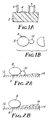
- Figures 1a and b illustrate the production of a masking material in accordance with one embodiment of the invention.
- Figure 1a shows, in cross-section, a portion of a foam web (2) on which is coated a stripe of pressure-sensitive adhesive (4).
- the foam web is passed through a multi-slitter fitted with crush cutter blades (6).
- Three crush cutter blades (6) are shown which are spaced an appropriate distance apart to form a primary cord (8) and a secondary cord (10).
- a repeating arrangement of such cutter blades may extend across the full width of the web to produce a multiple array of masking strips.
- a primary cord (8) having the stripe of pressure-sensitive adhesive (4) is formed joined to a secondary cord (10) by a common cold-weld.
- the secondary cord (10) is readily separable from the primary cord (8) by tearing along the weld.
- Figures 2a and b illustrate the use of the masking material.
- the masking material is secured to a surface (12) to be coated by the pressure-sensitive adhesive stripe (4).
- the masking material is positioned such that the secondary cord (10) contacts the surface (12) and is adjacent the area to be coated.
- a first coating (14) (shown in exaggerated thickness) is applied.
- the first coating (14) will be a primer. It will be noted that the coating (14) extends under the curvature of the secondary cord (10) resulting in a tapered or feathered edge to the coating (14).
- the secondary cord (10) is removed by tearing along the cold-weld.
- the primary cord (8) remains in position and a second coating (16) (shown in exaggerated thickness) is applied over the first coating (14).
- the second coating (16) extends over the edge of the coating (14) and under the overhanging curvature of the primary cord (8) thereby assuring that none of the coating (14) is exposed and providing a feathered edge to the coating (16). Thereafter, the primary cord (8) is removed.
- the dimensions of the primary and secondary cords may be varied by suitable selection of the thickness of the foam web and spacing of the crushed cutter blades. Suitable masking materials have been produced from a foam web having a thickness of about 15mm to produce a substantially cylindrical primary cord having a diameter of approximately 13mm. Secondary cords of approximately 3, 6 and 7mm attached to the primary cord have been formed by suitable spacing of the crushed cutter blades.
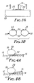
- FIGs 3a and b illustrate the production of a masking material in accordance with a second embodiment of the invention.
- a foam web (20) is coated with two stripes of pressure-sensitive adhesive (22, 24) and a second thinner foam web (25) e.g., having a thickness of 2 to 5mm, is placed such that it overlaps, but does not completely cover, the adhesive strips (22, 24).
- the composite web is fed into a multi-slitter fitted with crushed cutter blades the positions of which are shown at 26. The crush cutter blades compress the foam web forming cold-welds resulting in the production of two separate masking strips (28).
- Each masking strip (28) comprises a substantially cylindrical portion (30) formed from the foam web (20), an adhesive stripe (22, 24) and a removable edge portion (32) formed from the foam web (25) which is secured to the cylindrical portion (30) by the adhesive stripe (22, 24) and a cold-weld.
- the removable edge (32) follows the cylindrical contour of the core (30).
- Figures 4a and b illustrate use of the masking material (28).
- the masking material is positioned on a surface (12) to be coated and secured by the pressure-sensitive adhesive stripe (22, or 24, not shown).
- the masking material is positioned such that the removable edge (32) is adjacent the edge of the area to be coated.
- a first coating material (14), e.g., primer, is applied, some of which extends beneath the overhang of the curve of the removable edge (32) to provide a feathered edge to the coating.
- the removable edge (32) is stripped from the core (30) without displacement of the core thereby exposing the curved surface of the core adjacent the edge of the area to be coated.
- a second coating (16) is applied over the first coating.
- the second coating (16) completely overlays the first coating and extends under the overhang of the curve of the core (30) thereby providing a feathered edge to the second coating.
- the masking material is removed.
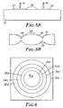
- FIGs 5a and b illustrate the production of a masking material similar to that disclosed in Figures 3 and 4 but having two removable edges.
- the masking material is formed from a foam web (31) on which two thin foam strips (33) are adhered by a pressure-sensitive adhesive or double sided pressure sensitive adhesive tape (not shown).
- the two foam strips (33) are separated by a gap (34) on which a stripe of pressure-sensitive adhesive is applied either before or after cold-welding.
- the composite web is fed into a multi-slitter fitted with crusher blades (36) which compress the foam and form a cold-weld.
- the resultant masking material is shown in Figure 5b and comprises an array of masking material each comprising a central core (38) and a pair of removable edges (40). Adjacent masking strips are adhered to each other by the cold-weld but are readily separable. Each masking strip may be used in the manner described with reference to Figures 4a and b.
- Figure 6 of the accompanying drawings illustrates a variable size painting mask which is made by die stamping a foam web e.g., 5mm thick, in a manner such that the die steel does not cut all the way through the foam but the foam is marked with a series of concentric cold-welds.
- the overall masking material may be in the region of 1 metre square and comprise a plurality of concentric welds (50a to 50d) defining annular segments (52a to 52d).
- segment (52a) one or more segments of the mask large enough to completely reveal the area to be painted is removed e.g., segment (52a), and the mask applied to the surface and held in place by a layer of adhesive (not shown).
- a first coating material is applied, the mask allowing formation of a feathered edge due to the curvature caused by the cold-weld.
- the inner segment of the mask e.g., segment (52b) is then removed by tearing the cold-weld thereby exposing a further curved surface.
- a second coating material is applied over the first coat, the curve of the remaining masking material causing a feathering effect at the edge of the top layer. It will be appreciated that a variety of shapes other than circular may be employed for the variable size painting mask.
Landscapes
- Details Or Accessories Of Spraying Plant Or Apparatus (AREA)
- Application Of Or Painting With Fluid Materials (AREA)
- Adhesive Tapes (AREA)
Applications Claiming Priority (3)
| Application Number | Priority Date | Filing Date | Title |
|---|---|---|---|
| GB9804967 | 1998-03-09 | ||
| GBGB9804967.9A GB9804967D0 (en) | 1998-03-09 | 1998-03-09 | Masking materials and method of use |
| PCT/US1999/005053 WO1999046056A1 (en) | 1998-03-09 | 1999-03-09 | Masking materials and method of use |
Publications (2)
| Publication Number | Publication Date |
|---|---|
| EP1062050A1 EP1062050A1 (en) | 2000-12-27 |
| EP1062050B1 true EP1062050B1 (en) | 2005-05-25 |
Family
ID=10828229
Family Applications (1)
| Application Number | Title | Priority Date | Filing Date |
|---|---|---|---|
| EP99909921A Expired - Lifetime EP1062050B1 (en) | 1998-03-09 | 1999-03-09 | Masking materials and method of use |
Country Status (10)
| Country | Link |
|---|---|
| EP (1) | EP1062050B1 (enExample) |
| JP (1) | JP4274695B2 (enExample) |
| KR (1) | KR100563873B1 (enExample) |
| CN (1) | CN1106889C (enExample) |
| BR (1) | BR9908640A (enExample) |
| CA (1) | CA2322956C (enExample) |
| DE (1) | DE69925465T2 (enExample) |
| ES (1) | ES2241266T3 (enExample) |
| GB (1) | GB9804967D0 (enExample) |
| WO (1) | WO1999046056A1 (enExample) |
Families Citing this family (9)
| Publication number | Priority date | Publication date | Assignee | Title |
|---|---|---|---|---|
| US6596376B1 (en) | 1999-03-09 | 2003-07-22 | 3M Innovative Properties Company | Masking materials and method of use |
| GB0109177D0 (en) * | 2001-04-12 | 2001-05-30 | 3M Innovative Properties Co | Improvements in or relating to foam articles |
| KR100503384B1 (ko) * | 2002-02-26 | 2005-07-26 | 김희식 | 인덕션 가열기용 조리용기의 부분적 도장 방지용 조성물및 부분적 도장 방지방법 |
| TWD102057S1 (zh) | 2002-07-13 | 2004-12-21 | 新設資產公司 | 遮蔽條 |
| ES2241409B1 (es) * | 2002-12-04 | 2006-07-16 | Boss Auto Import S.A. | Dispositivo para la fabricacion de burletes de goma. |
| ATE510629T1 (de) * | 2005-04-22 | 2011-06-15 | 3M Innovative Properties Co | Abdeckartikel und verfahren zum abdecken eines zu beschichtenden substrats |
| USD751358S1 (en) | 2007-11-09 | 2016-03-15 | 3M Innovative Properties Company | Masking article |
| GB2497540B (en) * | 2011-12-13 | 2016-06-22 | Pexa Ltd | Masking apparatus |
| DE102012223440A1 (de) * | 2012-12-17 | 2014-06-18 | Kunststoff-Technik Scherer & Trier Gmbh & Co. Kg | Verfahren zum Lackieren einer zumindest zweifarbigen, stufenfreien Karosserieleiste, Maskierschablone, Karosserieleiste |
Family Cites Families (6)
| Publication number | Priority date | Publication date | Assignee | Title |
|---|---|---|---|---|
| US4996092A (en) * | 1989-02-20 | 1991-02-26 | Minnesota Mining And Manufacturing Company | Shaped foam |
| US5413637A (en) * | 1991-04-19 | 1995-05-09 | Minnesota Mining And Manufacturing Company | Masking methods using a foam web |
| GB2254811B (en) * | 1991-04-19 | 1994-11-30 | Minnesota Mining & Mfg | Masking methods using a foam web |
| GB9402812D0 (en) * | 1994-02-14 | 1994-04-06 | Speedarrive Projects Limited | For a sealing strip |
| GB2288137A (en) | 1994-03-08 | 1995-10-11 | Minnesota Mining & Mfg | Masking the "B" post of a vehicle using a foam strip |
| DE59601995D1 (de) * | 1996-03-11 | 1999-07-01 | Voss Chemie | Dicht- und Abdeckstreifen |
-
1998
- 1998-03-09 GB GBGB9804967.9A patent/GB9804967D0/en not_active Ceased
-
1999
- 1999-03-09 CA CA002322956A patent/CA2322956C/en not_active Expired - Fee Related
- 1999-03-09 KR KR1020007009946A patent/KR100563873B1/ko not_active Expired - Fee Related
- 1999-03-09 CN CN99803794A patent/CN1106889C/zh not_active Expired - Fee Related
- 1999-03-09 BR BR9908640-9A patent/BR9908640A/pt not_active IP Right Cessation
- 1999-03-09 WO PCT/US1999/005053 patent/WO1999046056A1/en not_active Ceased
- 1999-03-09 DE DE69925465T patent/DE69925465T2/de not_active Expired - Lifetime
- 1999-03-09 EP EP99909921A patent/EP1062050B1/en not_active Expired - Lifetime
- 1999-03-09 ES ES99909921T patent/ES2241266T3/es not_active Expired - Lifetime
- 1999-03-09 JP JP2000535461A patent/JP4274695B2/ja not_active Expired - Fee Related
Also Published As
| Publication number | Publication date |
|---|---|
| ES2241266T3 (es) | 2005-10-16 |
| JP2002505950A (ja) | 2002-02-26 |
| KR100563873B1 (ko) | 2006-03-27 |
| BR9908640A (pt) | 2000-11-14 |
| WO1999046056A1 (en) | 1999-09-16 |
| CA2322956A1 (en) | 1999-09-16 |
| CN1106889C (zh) | 2003-04-30 |
| KR20010041717A (ko) | 2001-05-25 |
| DE69925465D1 (de) | 2005-06-30 |
| DE69925465T2 (de) | 2006-05-11 |
| GB9804967D0 (en) | 1998-05-06 |
| CN1292732A (zh) | 2001-04-25 |
| CA2322956C (en) | 2008-05-20 |
| EP1062050A1 (en) | 2000-12-27 |
| JP4274695B2 (ja) | 2009-06-10 |
Similar Documents
| Publication | Publication Date | Title |
|---|---|---|
| US6596376B1 (en) | Masking materials and method of use | |
| US7175732B2 (en) | Method of applying seam tape to the edge of a membrane | |
| EP1062050B1 (en) | Masking materials and method of use | |
| US4996092A (en) | Shaped foam | |
| US6627259B1 (en) | Masking tapes and application methods | |
| EP1539369B1 (en) | Masking strip | |
| CA2075631A1 (en) | Paint masking assembly and method of masking | |
| EP1377425B1 (en) | Improved foam masking device, and method of manufacturing such a device | |
| DE2721420A1 (de) | Dosenfoermiger aufreiss-behaelter sowie verfahren und vorrichtung zu seiner herstellung | |
| AU2002250560A1 (en) | Improved foam masking device | |
| US5413637A (en) | Masking methods using a foam web | |
| KR100343820B1 (ko) | 마스킹방법 | |
| WO1999012654A2 (en) | Masking tapes and application methods | |
| US20050006021A1 (en) | Foam articles | |
| EP0580804B1 (en) | Masking methods using a foam web | |
| US10232396B2 (en) | Method for masking a gap | |
| JPH0337739Y2 (enExample) | ||
| GB2425076A (en) | Masking tape | |
| DE9007753U1 (de) | Geformter Schaum |
Legal Events
| Date | Code | Title | Description |
|---|---|---|---|
| PUAI | Public reference made under article 153(3) epc to a published international application that has entered the european phase |
Free format text: ORIGINAL CODE: 0009012 |
|
| 17P | Request for examination filed |
Effective date: 20000824 |
|
| AK | Designated contracting states |
Kind code of ref document: A1 Designated state(s): DE ES FR GB IT |
|
| 17Q | First examination report despatched |
Effective date: 20030610 |
|
| GRAP | Despatch of communication of intention to grant a patent |
Free format text: ORIGINAL CODE: EPIDOSNIGR1 |
|
| GRAS | Grant fee paid |
Free format text: ORIGINAL CODE: EPIDOSNIGR3 |
|
| GRAA | (expected) grant |
Free format text: ORIGINAL CODE: 0009210 |
|
| AK | Designated contracting states |
Kind code of ref document: B1 Designated state(s): DE ES FR GB IT |
|
| REG | Reference to a national code |
Ref country code: GB Ref legal event code: FG4D |
|
| REF | Corresponds to: |
Ref document number: 69925465 Country of ref document: DE Date of ref document: 20050630 Kind code of ref document: P |
|
| REG | Reference to a national code |
Ref country code: ES Ref legal event code: FG2A Ref document number: 2241266 Country of ref document: ES Kind code of ref document: T3 |
|
| ET | Fr: translation filed | ||
| PLBE | No opposition filed within time limit |
Free format text: ORIGINAL CODE: 0009261 |
|
| STAA | Information on the status of an ep patent application or granted ep patent |
Free format text: STATUS: NO OPPOSITION FILED WITHIN TIME LIMIT |
|
| 26N | No opposition filed |
Effective date: 20060228 |
|
| REG | Reference to a national code |
Ref country code: FR Ref legal event code: PLFP Year of fee payment: 17 |
|
| PGFP | Annual fee paid to national office [announced via postgrant information from national office to epo] |
Ref country code: IT Payment date: 20150224 Year of fee payment: 17 Ref country code: DE Payment date: 20150305 Year of fee payment: 17 Ref country code: ES Payment date: 20150212 Year of fee payment: 17 |
|
| PGFP | Annual fee paid to national office [announced via postgrant information from national office to epo] |
Ref country code: FR Payment date: 20150309 Year of fee payment: 17 Ref country code: GB Payment date: 20150304 Year of fee payment: 17 |
|
| REG | Reference to a national code |
Ref country code: DE Ref legal event code: R119 Ref document number: 69925465 Country of ref document: DE |
|
| GBPC | Gb: european patent ceased through non-payment of renewal fee |
Effective date: 20160309 |
|
| REG | Reference to a national code |
Ref country code: FR Ref legal event code: ST Effective date: 20161130 |
|
| PG25 | Lapsed in a contracting state [announced via postgrant information from national office to epo] |
Ref country code: DE Free format text: LAPSE BECAUSE OF NON-PAYMENT OF DUE FEES Effective date: 20161001 Ref country code: FR Free format text: LAPSE BECAUSE OF NON-PAYMENT OF DUE FEES Effective date: 20160331 Ref country code: GB Free format text: LAPSE BECAUSE OF NON-PAYMENT OF DUE FEES Effective date: 20160309 |
|
| PG25 | Lapsed in a contracting state [announced via postgrant information from national office to epo] |
Ref country code: IT Free format text: LAPSE BECAUSE OF NON-PAYMENT OF DUE FEES Effective date: 20160309 |
|
| REG | Reference to a national code |
Ref country code: ES Ref legal event code: FD2A Effective date: 20170427 |
|
| PG25 | Lapsed in a contracting state [announced via postgrant information from national office to epo] |
Ref country code: ES Free format text: LAPSE BECAUSE OF NON-PAYMENT OF DUE FEES Effective date: 20160310 |