EP1377425B1 - Improved foam masking device, and method of manufacturing such a device - Google Patents
Improved foam masking device, and method of manufacturing such a device Download PDFInfo
- Publication number
- EP1377425B1 EP1377425B1 EP02719481A EP02719481A EP1377425B1 EP 1377425 B1 EP1377425 B1 EP 1377425B1 EP 02719481 A EP02719481 A EP 02719481A EP 02719481 A EP02719481 A EP 02719481A EP 1377425 B1 EP1377425 B1 EP 1377425B1
- Authority
- EP
- European Patent Office
- Prior art keywords
- foam
- strips
- strip
- cord
- article
- Prior art date
- Legal status (The legal status is an assumption and is not a legal conclusion. Google has not performed a legal analysis and makes no representation as to the accuracy of the status listed.)
- Expired - Lifetime
Links
- 239000006260 foam Substances 0.000 title claims abstract description 329
- 230000000873 masking effect Effects 0.000 title claims abstract description 100
- 238000004519 manufacturing process Methods 0.000 title claims description 9
- 239000000463 material Substances 0.000 claims abstract description 92
- 239000000853 adhesive Substances 0.000 claims abstract description 50
- 230000001070 adhesive effect Effects 0.000 claims abstract description 50
- 239000006261 foam material Substances 0.000 claims description 29
- 238000000034 method Methods 0.000 claims description 18
- 238000003466 welding Methods 0.000 claims description 10
- 238000005304 joining Methods 0.000 claims description 3
- 238000007592 spray painting technique Methods 0.000 abstract 1
- 239000010410 layer Substances 0.000 description 142
- 238000010422 painting Methods 0.000 description 17
- 230000008901 benefit Effects 0.000 description 9
- 238000002156 mixing Methods 0.000 description 9
- 238000010276 construction Methods 0.000 description 7
- 230000004048 modification Effects 0.000 description 7
- 238000012986 modification Methods 0.000 description 7
- 239000003973 paint Substances 0.000 description 6
- 239000004820 Pressure-sensitive adhesive Substances 0.000 description 5
- 239000003086 colorant Substances 0.000 description 4
- 239000000758 substrate Substances 0.000 description 3
- 239000004698 Polyethylene Substances 0.000 description 2
- 239000004793 Polystyrene Substances 0.000 description 2
- 229920002323 Silicone foam Polymers 0.000 description 2
- 238000007607 die coating method Methods 0.000 description 2
- 229920001971 elastomer Polymers 0.000 description 2
- 239000012943 hotmelt Substances 0.000 description 2
- 229920000728 polyester Polymers 0.000 description 2
- -1 polyethylene Polymers 0.000 description 2
- 229920000573 polyethylene Polymers 0.000 description 2
- 229920001228 polyisocyanate Polymers 0.000 description 2
- 239000005056 polyisocyanate Substances 0.000 description 2
- 150000008442 polyphenolic compounds Chemical class 0.000 description 2
- 235000013824 polyphenols Nutrition 0.000 description 2
- 229920002223 polystyrene Polymers 0.000 description 2
- 229920002635 polyurethane Polymers 0.000 description 2
- 239000004814 polyurethane Substances 0.000 description 2
- 229920000915 polyvinyl chloride Polymers 0.000 description 2
- 239000004800 polyvinyl chloride Substances 0.000 description 2
- 230000009467 reduction Effects 0.000 description 2
- 230000008439 repair process Effects 0.000 description 2
- 230000006835 compression Effects 0.000 description 1
- 238000007906 compression Methods 0.000 description 1
- 239000012792 core layer Substances 0.000 description 1
- 238000012864 cross contamination Methods 0.000 description 1
- 238000005520 cutting process Methods 0.000 description 1
- 239000000203 mixture Substances 0.000 description 1
- 238000003825 pressing Methods 0.000 description 1
- 230000008569 process Effects 0.000 description 1
- 239000007921 spray Substances 0.000 description 1
Images


Classifications
-
- B—PERFORMING OPERATIONS; TRANSPORTING
- B29—WORKING OF PLASTICS; WORKING OF SUBSTANCES IN A PLASTIC STATE IN GENERAL
- B29C—SHAPING OR JOINING OF PLASTICS; SHAPING OF MATERIAL IN A PLASTIC STATE, NOT OTHERWISE PROVIDED FOR; AFTER-TREATMENT OF THE SHAPED PRODUCTS, e.g. REPAIRING
- B29C44/00—Shaping by internal pressure generated in the material, e.g. swelling or foaming ; Producing porous or cellular expanded plastics articles
- B29C44/02—Shaping by internal pressure generated in the material, e.g. swelling or foaming ; Producing porous or cellular expanded plastics articles for articles of definite length, i.e. discrete articles
- B29C44/04—Shaping by internal pressure generated in the material, e.g. swelling or foaming ; Producing porous or cellular expanded plastics articles for articles of definite length, i.e. discrete articles consisting of at least two parts of chemically or physically different materials, e.g. having different densities
- B29C44/06—Making multilayered articles
-
- B—PERFORMING OPERATIONS; TRANSPORTING
- B05—SPRAYING OR ATOMISING IN GENERAL; APPLYING FLUENT MATERIALS TO SURFACES, IN GENERAL
- B05B—SPRAYING APPARATUS; ATOMISING APPARATUS; NOZZLES
- B05B12/00—Arrangements for controlling delivery; Arrangements for controlling the spray area
- B05B12/16—Arrangements for controlling delivery; Arrangements for controlling the spray area for controlling the spray area
- B05B12/20—Masking elements, i.e. elements defining uncoated areas on an object to be coated
- B05B12/26—Masking elements, i.e. elements defining uncoated areas on an object to be coated for masking cavities
- B05B12/265—Masking elements, i.e. elements defining uncoated areas on an object to be coated for masking cavities between a door and a post, e.g. foam strips
-
- Y—GENERAL TAGGING OF NEW TECHNOLOGICAL DEVELOPMENTS; GENERAL TAGGING OF CROSS-SECTIONAL TECHNOLOGIES SPANNING OVER SEVERAL SECTIONS OF THE IPC; TECHNICAL SUBJECTS COVERED BY FORMER USPC CROSS-REFERENCE ART COLLECTIONS [XRACs] AND DIGESTS
- Y10—TECHNICAL SUBJECTS COVERED BY FORMER USPC
- Y10T—TECHNICAL SUBJECTS COVERED BY FORMER US CLASSIFICATION
- Y10T428/00—Stock material or miscellaneous articles
- Y10T428/23—Sheet including cover or casing
- Y10T428/233—Foamed or expanded material encased
-
- Y—GENERAL TAGGING OF NEW TECHNOLOGICAL DEVELOPMENTS; GENERAL TAGGING OF CROSS-SECTIONAL TECHNOLOGIES SPANNING OVER SEVERAL SECTIONS OF THE IPC; TECHNICAL SUBJECTS COVERED BY FORMER USPC CROSS-REFERENCE ART COLLECTIONS [XRACs] AND DIGESTS
- Y10—TECHNICAL SUBJECTS COVERED BY FORMER USPC
- Y10T—TECHNICAL SUBJECTS COVERED BY FORMER US CLASSIFICATION
- Y10T428/00—Stock material or miscellaneous articles
- Y10T428/23907—Pile or nap type surface or component
- Y10T428/23929—Edge feature or configured or discontinuous surface
-
- Y—GENERAL TAGGING OF NEW TECHNOLOGICAL DEVELOPMENTS; GENERAL TAGGING OF CROSS-SECTIONAL TECHNOLOGIES SPANNING OVER SEVERAL SECTIONS OF THE IPC; TECHNICAL SUBJECTS COVERED BY FORMER USPC CROSS-REFERENCE ART COLLECTIONS [XRACs] AND DIGESTS
- Y10—TECHNICAL SUBJECTS COVERED BY FORMER USPC
- Y10T—TECHNICAL SUBJECTS COVERED BY FORMER US CLASSIFICATION
- Y10T428/00—Stock material or miscellaneous articles
- Y10T428/24—Structurally defined web or sheet [e.g., overall dimension, etc.]
- Y10T428/24479—Structurally defined web or sheet [e.g., overall dimension, etc.] including variation in thickness
- Y10T428/24496—Foamed or cellular component
-
- Y—GENERAL TAGGING OF NEW TECHNOLOGICAL DEVELOPMENTS; GENERAL TAGGING OF CROSS-SECTIONAL TECHNOLOGIES SPANNING OVER SEVERAL SECTIONS OF THE IPC; TECHNICAL SUBJECTS COVERED BY FORMER USPC CROSS-REFERENCE ART COLLECTIONS [XRACs] AND DIGESTS
- Y10—TECHNICAL SUBJECTS COVERED BY FORMER USPC
- Y10T—TECHNICAL SUBJECTS COVERED BY FORMER US CLASSIFICATION
- Y10T428/00—Stock material or miscellaneous articles
- Y10T428/24—Structurally defined web or sheet [e.g., overall dimension, etc.]
- Y10T428/24777—Edge feature
-
- Y—GENERAL TAGGING OF NEW TECHNOLOGICAL DEVELOPMENTS; GENERAL TAGGING OF CROSS-SECTIONAL TECHNOLOGIES SPANNING OVER SEVERAL SECTIONS OF THE IPC; TECHNICAL SUBJECTS COVERED BY FORMER USPC CROSS-REFERENCE ART COLLECTIONS [XRACs] AND DIGESTS
- Y10—TECHNICAL SUBJECTS COVERED BY FORMER USPC
- Y10T—TECHNICAL SUBJECTS COVERED BY FORMER US CLASSIFICATION
- Y10T428/00—Stock material or miscellaneous articles
- Y10T428/249921—Web or sheet containing structurally defined element or component
- Y10T428/249953—Composite having voids in a component [e.g., porous, cellular, etc.]
- Y10T428/24996—With internal element bridging layers, nonplanar interface between layers, or intermediate layer of commingled adjacent foam layers
-
- Y—GENERAL TAGGING OF NEW TECHNOLOGICAL DEVELOPMENTS; GENERAL TAGGING OF CROSS-SECTIONAL TECHNOLOGIES SPANNING OVER SEVERAL SECTIONS OF THE IPC; TECHNICAL SUBJECTS COVERED BY FORMER USPC CROSS-REFERENCE ART COLLECTIONS [XRACs] AND DIGESTS
- Y10—TECHNICAL SUBJECTS COVERED BY FORMER USPC
- Y10T—TECHNICAL SUBJECTS COVERED BY FORMER US CLASSIFICATION
- Y10T428/00—Stock material or miscellaneous articles
- Y10T428/249921—Web or sheet containing structurally defined element or component
- Y10T428/249953—Composite having voids in a component [e.g., porous, cellular, etc.]
- Y10T428/249978—Voids specified as micro
- Y10T428/24998—Composite has more than two layers
-
- Y—GENERAL TAGGING OF NEW TECHNOLOGICAL DEVELOPMENTS; GENERAL TAGGING OF CROSS-SECTIONAL TECHNOLOGIES SPANNING OVER SEVERAL SECTIONS OF THE IPC; TECHNICAL SUBJECTS COVERED BY FORMER USPC CROSS-REFERENCE ART COLLECTIONS [XRACs] AND DIGESTS
- Y10—TECHNICAL SUBJECTS COVERED BY FORMER USPC
- Y10T—TECHNICAL SUBJECTS COVERED BY FORMER US CLASSIFICATION
- Y10T428/00—Stock material or miscellaneous articles
- Y10T428/249921—Web or sheet containing structurally defined element or component
- Y10T428/249953—Composite having voids in a component [e.g., porous, cellular, etc.]
- Y10T428/249981—Plural void-containing components
-
- Y—GENERAL TAGGING OF NEW TECHNOLOGICAL DEVELOPMENTS; GENERAL TAGGING OF CROSS-SECTIONAL TECHNOLOGIES SPANNING OVER SEVERAL SECTIONS OF THE IPC; TECHNICAL SUBJECTS COVERED BY FORMER USPC CROSS-REFERENCE ART COLLECTIONS [XRACs] AND DIGESTS
- Y10—TECHNICAL SUBJECTS COVERED BY FORMER USPC
- Y10T—TECHNICAL SUBJECTS COVERED BY FORMER US CLASSIFICATION
- Y10T428/00—Stock material or miscellaneous articles
- Y10T428/249921—Web or sheet containing structurally defined element or component
- Y10T428/249953—Composite having voids in a component [e.g., porous, cellular, etc.]
- Y10T428/249982—With component specified as adhesive or bonding agent
- Y10T428/249983—As outermost component
-
- Y—GENERAL TAGGING OF NEW TECHNOLOGICAL DEVELOPMENTS; GENERAL TAGGING OF CROSS-SECTIONAL TECHNOLOGIES SPANNING OVER SEVERAL SECTIONS OF THE IPC; TECHNICAL SUBJECTS COVERED BY FORMER USPC CROSS-REFERENCE ART COLLECTIONS [XRACs] AND DIGESTS
- Y10—TECHNICAL SUBJECTS COVERED BY FORMER USPC
- Y10T—TECHNICAL SUBJECTS COVERED BY FORMER US CLASSIFICATION
- Y10T428/00—Stock material or miscellaneous articles
- Y10T428/249921—Web or sheet containing structurally defined element or component
- Y10T428/249953—Composite having voids in a component [e.g., porous, cellular, etc.]
- Y10T428/249987—With nonvoid component of specified composition
- Y10T428/249991—Synthetic resin or natural rubbers
Definitions
- This invention concerns improvements in or relating to foam articles.
- the invention has particular, but not exclusive, application to foam articles for use as masking materials when painting part of a vehicle to protect another part of the vehicle so that paint is only applied to the selected part of the vehicle.
- the invention also concerns a method of manufacturing such foam articles.
- the invention relates to foam articles for use as masking materials to block temporarily a gap between two parts of a vehicle to prevent paint entering the gap when the vehicle is being spray painted.
- the foam articles of this invention are especially suitable for use in vehicle body shops when respraying part of a vehicle following a repair.
- the foam strip has a longitudinally extending stripe of pressure sensitive adhesive by means of which the foam strip can be secured in the required position prior to painting and subsequently removed after painting.
- the size and shape of the gap, and the available surface for mounting the foam strip may vary according to the position of the gap.
- the "A" post is the pillar situated between the vehicle body and the front edge of the front door
- the "B” post is the pillar situated between the rear edge of the front door and the front edge of the rear door
- the "C” post is the pillar situated between the rear edge of the rear door and the vehicle body.
- the "A" post supports the hinges for the front door
- the "B” post supports the catch for the front door and the hinges for the rear door
- the "C” post supports the catch for the rear door.
- a different type of foam strip is required to block the gap formed at each of these positions with each type of foam strip being provided in a range of sizes to accommodate variations in the dimensions of the gap between different makes or models of vehicle.
- the user has to select and fit the correct type and size of foam strip for a given application, and use of the wrong foam strip may allow paint to penetrate the gap requiring corrective work to be carried out. This involves extra time and materials to complete a repair which reduces efficiency and profitability.
- a foam strip is disclosed in International Patent Application No. WO99/52646 assigned to the assignee of the present application having a generally elongate cross-section with rounded ends which can be used as a masking material in more than one position when painting a vehicle.
- the foam strip of this application can be used to mask the gap formed at the "A" or "B" post of a vehicle as well as the gap formed between the rear edge of the vehicle body and a tailgate.
- foam strip reduces the number of types of foam strip required for use at different positions of the vehicle and offers significant advantages and benefits to the user by allowing the same foam strip to be used in more than one location.
- the problem still remains however that a given thickness of foam strip may not be capable of masking gaps of different size and different thicknesses of foam strips may still be required for effective masking of these gaps.
- the foam strips currently used as masking materials including the foam strip of WO99/52646 require access to the gap to be masked for securing the foam strip by means of the adhesive stripe and particular problems arise when masking the "A" post.
- the foam strips currently used as masking materials including the foam strip of WO99/52646 require access to the gap to be masked for securing the foam strip by means of the adhesive stripe and particular problems arise when masking the "A" post.
- attaching the foam strip in the required position to mask across the gap when the door is closed is often a difficult and time consuming operation.
- the existing foam strips including the foam strip of WO99/52646 are only suitable for use once and, after painting, are removed and thrown away.
- the exposed portion of the foam strip is painted and the foam strip cannot be re-attached to conceal the painted portion and present a new, clean portion of the strip.
- re-use of the foam strip is at best unsatisfactory and is generally avoided.
- a masking material comprises an elongate strip at least partially coated with a layer of a pressure-sensitive adhesive, the strip having a curved surface which is convex when the strip is viewed in cross section and is positioned such that when the strip is adhered to a substrate by the layer of pressure-sensitive adhesive a portion of the curved surface overhangs the substrate.
- the masking material comprises a removable edge portion comprising said portion of the curved surface detachably secured to a remainder of the strip and which may be removed to expose a second curved surface on the remainder of the strip which is convex when viewed in cross section and which is positioned to overhang the substrate.
- the present invention provides a foam article which can be used as a masking material having an even wider range of application for masking gaps of different types and different sizes than existing masking materials.
- the present invention provides a foam article for use as a masking material that is capable of being secured in position without the use of adhesive.
- the present invention provides such a foam article for use as a masking material that can be used where access to a surface for adhesively securing the article is limited or restricted.
- the present invention provides such a foam article for use as a masking material that can be used more than once.
- the present invention provides a foam article, the manufacture of such article and the use thereof as a masking material to mask a gap when painting a vehicle which has generally universal application for masking gaps at different locations and in a range of sizes.
- the present invention provides a foam article for use as a masking material comprising at least three elongate foam strips, each strip having a longitudinally extending edge and being joined at said longitudinally extending edge to a longitudinally extending edge of at least one further elongate strip by a seam common to all said strips.
- the foam article By forming the foam article from at least three foam strips, the foam article can be adapted to provide masking material of the required thickness for use in any selected one of a range of different types and size of gap by the selection of the appropriate number of foam strips to mask the gap.
- the masking material can be re-used by arranging the foam strips to mask a gap with fresh or clean surfaces of the masking material exposed.
- each foam strip is of generally elongate cross-section having longitudinally extending edges on opposite sides of a longitudinally extending body portion.
- the common seam joins all the foam strips along one side edge and the other side edge is free.
- the foam strips are secured longitudinally to radiate from said common seam.
- the foam strips can be arranged to superimpose different combinations of the foam strips to provide different thicknesses of masking material.
- the foam strips are separable along said common seam. In this way, any foam strips that are not required can be removed to leave the desired thickness of masking material.
- any foam strips that are painted can be removed and the remaining foam strips arranged to provide masking material for another use.
- Removing any painted foam strips reduces the thickness of masking material that can be produced with the remaining foam strips. It may be possible to re-use the masking material without reducing the thickness by re-arranging the foam strips so that any painted foam strips are concealed by unpainted foam strips when the masking material is secured in position.
- the common seam joins all the foam strips along one side edge and a further common seam joins all the foam strips along the other side edge.
- the foam strips are secured relative to each other in a superimposed relationship to provide masking material having a thickness corresponding substantially to the combined thickness of the individual foam strips.
- the foam strips are separable along said common seams. In this way, the outermost foam strips can be removed to vary the thickness of the masking material.
- any foam strips that are covered in paint can be removed and the remaining foam strips arranged to provide masking material for another use.
- the number and/or thickness of the foam strips may be chosen to provide the masking material with any desired range of thicknesses by selecting an appropriate combination of foam strips.
- the foam strips may all be of the same thickness or at least one foam strip may be of different thickness to the other foam strip(s).
- the foam strips are selected when combined to provide masking material having a maximum thickness of up to about 30mm.
- the foam material of the foam strips may be chosen to provide the masking material with any desired properties.
- the foam strips may all be of the same type of foam material or at least one foam strip may be of a different type of foam material.
- the foam material employed may be an open or closed cell polymeric foam that is resiliently compressible for conforming to a required shape for a given application.
- Foams having a density in the range of from 20 to 30Kg/m 3 are generally found to be useful for use as masking materials.
- the foam strips may all be of the same colour. Alternatively, different properties or characteristics of the foam strips such as thickness or type of foam material, may be distinguished by different colours or combinations of colours. Colour coding the foam strips in this way has advantages for both the manufacture and use of masking materials with the appropriate combination of foam strips for the required application.
- Different colours may also be used to provide a colour contrast de-limiting a sight line at the boundary between differently coloured portions of the foam strips to assist in accurately positioning the masking material.
- the foam strips are made of cold weldable material.
- the foam article may be produced by forming a cold weld seam along at least one side edge of the foam strips.
- Preferred foam materials include polystyrene, polyvinylchloride, polyethylene, polyurethane, polyisocyanate, polyphenol, polyester and silicone foams.
- the foam material may be cold welded by applying pressure to superimposed layers of foam web with a former such as a rotatable pressure roller or wheel so as to compress the layers of foam web sufficiently to cause the foam layers to fuse together.
- a former such as a rotatable pressure roller or wheel
- a cold weld seam formed in this way unites the layers of foam material to each other along the seam and allows individual layers to be separated from the other layers which remain united along the seam.
- the foam articles may be provided with a longitudinal adhesive stripe on at least one foam strip for sticking the foam article in position.
- Preferred adhesives are pressure sensitive adhesives such as a hot melt rubber adhesive.
- the adhesive may be applied to the foam by any suitable means, for example die coating, before or after the cold welding operation.
- the present invention provides a method of manufacturing a foam article for use as a masking material including the steps of providing at least three sheets of foam material, superimposing the sheets of foam material, joining the sheets of foam material at a plurality of spaced positions by longitudinally extending parallel seams, and separating the sheets of foam material along the seams to produce a plurality of elongate foam articles, wherein each foam article comprises at least three foam strips joined together by at least one seam a side edge of the foam strips.
- the foam article produced by the above method may have the foam strips joined together along both side edges so that the foam strips are secured in superimposed relationship to each other.
- This form of the foam article can be used as a masking material and can be adapted to a required thickness of masking material for a given application by removing one or more of the foam strips.
- the foam strips may be joined together along one side edge only so that the foam strips radiate from the seam.
- This form of the foam article can also be used as a masking material and can be adapted to any desired thickness by superimposing the appropriate number of foam strips.
- the foam material is cold weldable and the seams are formed by compressing the sheets of foam material to fuse the sheets together along the seams.
- the cold welding operation may be effected by a former such as a rotary pressure wheel or roller and a plurality of seams may be formed simultaneously by arranging a series of formers transversely spaced across the superimposed sheets of foam material.
- the foam strips are joined together by cold weld seams along both side edges when the sheets of foam material are separated to produce one form of foam article, and the seam along one side edge can be optionally ruptured if it is desired to produce another form of foam article.
- both forms of the foam article each comprising at least three foam strips can be produced by the same method.
- the foam strips can be arranged to provide any required thickness of masking material for a given application as described previously and, after use, the arrangement of the foam strips can be adapted so that the masking material can be re-used.
- any painted foam strips may be removed to expose a new, unpainted foam strip below for re-use of the masking material.
- any painted foam strips may be removed leaving the remaining new, unpainted foam strips for re-use of the masking material.
- the foam strips may be folded and superimposed in a different orientation so that the painted foam strips are concealed for re-use of the masking material.
- the arrangement of the foam strips can be adapted to enable the foam article to be re-used.
- any foam strip that has been painted when the foam article is used as a masking material can be removed so as to leave new, unpainted foam strips for further use of the foam article as a masking material.
- the foam articles of the present invention are particularly suited for use in masking a gap between two parts of a vehicle such as a door and the vehicle body or two doors.
- the foam article can be adapted to a range of gap sizes by selecting the combination of the individual foam strips to vary the thickness of the foam article.
- the arrangement of the foam strips can be adapted to vary the thickness of the foam article.
- a method can be considered of masking a gap between two parts of a vehicle when painting at least one of the parts, the method comprising the steps of providing an elongate foam article comprising a plurality of elongate foam strips joined together by a seam along at least one side edge, and positioning the foam article to mask the gap.
- the method may include the step of selecting a combination of foam strips to adapt the thickness of foam article to the gap to be masked.
- the method may also include the step of wedging the selected combination of foam strips in the gap without the use of adhesive.
- wedging the selected combination of foam strips in position may be of particular benefit if access to the gap is limited or restricted, for example when masking an "A" post.
- the selected combination of foam strips may be positioned in the gap and pulled through to wedge in the gap without the use of adhesive to secure the foam strip inside the gap.
- the foam article for use as a masking material comprises a plurality of superimposed foam strips releasably secured together.
- the foam strips may be secured together by cold welding or adhesive or any other suitable method that allows selective removal of one or more foam strips. In this way, different thicknesses of masking material can be obtained and/or, after use, contaminated foam strips can be removed to expose fresh strips allowing the masking material to be re-used.
- a foam article for use as a masking material embodying the present invention is made by cold welding at least three superimposed layers of foam web or sheet.
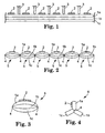
- three layers 1a, 1b, 1c of foam web are employed but it will be understood that the number of layers of foam webs employed may be varied depending on the requirements and intended application of the masking material.
- the layers 1a, 1b, 1c of foam web are shown in an uncompressed or free state in Figure 1.
- Each layer 1a, 1b, 1c is made of foam which is resiliently compressible and can be cold welded as described later herein.
- the foam may be open or closed cell polymeric foam and suitable types of foam include polystyrene, polyvinylchloride, polyethylene, polyurethane, polyisocyanate, polyphenol, polyester and silicone foams.
- Foams having a density of 20 to 30Kg/m 3 are generally useful for use as masking materials. Suitable foam materials are available under the trade designations "4273A” and "X4200AM” from Caligen Foam Limited of Broadoak, Accrington, Lancashire, England.
- each layer 1a, 1b, 1c is the same and has a thickness of 7mm. It will be understood, however that this is not essential and one or more of the layers 1a, 1b, 1c may be of different thickness and/or made of a different type of foam. Thus, any combination of thicknesses and/or foam materials may be employed depending on the requirements and intended application of the masking material. Alternatively or additionally, the layers 1a, 1b, 1c may be distinguished by colour for reasons discussed later.
- the upper layer la is provided with a plurality of spaced, parallel stripes 2 of an adhesive capable of adhering to the foam material.
- Suitable adhesives include pressure sensitive adhesives such as hot melt rubber adhesives that can be applied by die coating. Again, the selection and composition of the adhesive depends on the requirements and intended application of the masking material.
- the adhesive stripes 2 are applied to the foam web of the upper layer 1 a prior to joining the layers 1a, 1b, 1c together as described below. It will be understood, however, this is not essential and that the adhesive stripes 2 could be provided at any stage in the manufacture of the foam articles. Furthermore, adhesive stripes 2 could be applied to any of the foam webs forming the layers 1a, 1b, 1c. The arrangement of the stripes 2 depends on the requirements and intended application of the masking material.
- the layers 1a, 1b, 1c are cold welded by the application of pressure with rotary rollers or wheels 3 spaced apart a pre-determined distance to form a plurality of spaced, parallel seams 4 extending longitudinally of the webs.
- the rollers 3 compress the layers 1a, 1b, 1c so that the foam material fuses together to unite the layers 1a, 1b, 1c along the seams.
- the spacing between the seams 4 is about 20mm but this may be altered to suit the requirements and intended application of the masking material.
- Figure 2 shows the layers 1a, 1b, 1c after the cold welding operation to produce an array of longitudinally extending, parallel foam cords 5 joined by the cold weld seams 4.
- the foam cords 5 are separable from each other along the seams 4 either manually or by a suitable cutting device (not shown) and may be stored and supplied in rolls of pre-determined length wound on itself or a core (not shown) from which the user can unwind and separate a required length.
- More than one foam cord 5 of the same or different size may be wound on a common core. Where cords 5 of the same size are provided on a common core, these may be provided separately or joined together by the cold weld seams 4 and manually separated by the user when unwinding a required length of the selected cord 5.
- Figure 3 shows a single foam cord 5 separated from the array of foam cords 5 illustrated in Figure 2.
- the foam cord 5 has a generally elliptical shape in which the layers 1a, 1b, 1c of foam web form superimposed foam strips joined along both longitudinally extending side edges by cold weld seams 4.
- the shape of the foam cord 5 will depend on a number of factors including the thickness of the layers 1a, 1b, 1c of foam web, the number of layers 1a, 1b, 1c of foam web, the spacing between the cold weld seams 4, and the size and/or position of the adhesive stripe(s) 2. Varying any one or more of these may alter the shape of the foam cord from that illustrated and may be used to produce foam cords having an appropriate shape for any given application.
- the foam cord 5 shown in Figure 3 may be used in this form as a masking material when painting a vehicle to mask a gap between two parts of a vehicle to prevent paint entering the gap as described later herein.
- the foam cord 5 shown in Figure 3 may be converted to another form shown in Figure 4 by opening the cold weld seam 4 along one side edge of the foam layers 1a, 1b, 1c.
- foam cord 6 may also be used as a masking material when painting a vehicle to mask a gap between two parts of a vehicle to prevent paint entering the gap as described later herein.
- Figures 5A, 5B show cords 5, 6 made from six layers 1a, 1b, 1c, 1d, 1e, 1f of foam web of the same thickness, for example 4mm.
- Figures 6A, 6B show cords 5, 6 made from four layers 1a, 1b, 1c, 1d of foam web of different thicknesses, for example 4mm, 5mm, 6mm, 7mm.
- Figures 7A, 7B show cords 5, 6 in which an adhesive stripe 2 is provided on each layer 1a, 1b, 1c.
- Figures 8A, 8B show cords 5, 6 in which the layer 1a is of different colour to the layers 1b, 1c to indicate a difference in thickness or foam material between the layer la and the layers 1b, 1c.
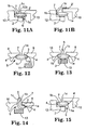
- Figures 9A, 9B, 9C, 9D show the use of the star-shaped foam cord 6 of Figure 4 to mask a gap 7 between the front edge 8a of a vehicle front door 8 and an adjacent edge 9a of a body part 9 such as a front wing to protect the A-post 11 when painting the door 8 and/or body part 9.
- the foam cord 6 is held by the foam layer la having the adhesive stripe 2.
- the door 8 is opened and the other foam layers 1b, 1c fed into the gap 7.
- the door 8 is then gently closed and the foam cord 6 fed along the length of the gap 7 by pulling through with the protruding layer 1a as shown in Figure 9A.
- the foam cord 6 is secured by folding down the layer la and sticking to the part 9 using the adhesive stripe 2 as shown in Figure 9B when painting the door 8.
- the orientation of the foam cord 6 may be reversed to stick the layer 1 a to the door 8 when painting the part 9.
- the foam cord 6 is pulled up so as to wedge the layers 1b, 1c in the gap 7 as shown in Figure 9C.
- the layer 1a is then removed by separating along the cold weld seam 4 as shown in Figure 9D.
- the cord 6 remains in place due to the friction wedging the layers 1b, 1c in the gap 7.
- Figures 10A, 10B show the use of the star-shaped cord 6 of Figure 4 to mask a gap 7 between the rear edge 8b of a vehicle front door 8 and the front edge 10a of a vehicle rear door 10 to protect the B-post 13 when painting the door 8 and/or door 10.
- the front door 8 is opened and the cord 6 secured by sticking the layer 1a to either the B-post 13 ( Figure 10A) or the inside of the door 8 ( Figure 10B) with the adhesive stripe 2.
- the layers 1b, 1c are folded down to overlie the layer 1a and held in place when the door 8 is closed.
- the cord 6 masks the gap 7 and allows blending across the gap 7.
- the layer 1c adjacent to the door 8 may have an adhesive stripe 2' as indicated in dotted lines to adhere to the inside of the closed door 8.
- the adhesive stripe 2' may be applied to the layer 1c prior to cold welding to join the layers 1a, 1b, 1c.
- the layer 1a is attached to the inside of the door 8 as shown in Figure 10B, one or both of the layers 1b, 1c protrudes through the gap 7 when the door 8 is closed. Any protruding layer 1b, 1c can be left if blending across the gap 7 is not required or pushed back into the gap 7 if blending across the gap 7 is required.
- Figures 11A, 11B show the use of the star-shaped cord 6 of Figure 4 to mask a gap 7 between the rear edge 10b of a rear door 10 and a body part 12 such as a rear wing to protect a C-post when painting the door 10 and/or part 12.
- the rear door 10 is opened and the cord 6 secured by sticking the layer la to the body part 12 with the adhesive stripe 2.
- the layers 1b, 1c are folded down to overlie the layer 1a and held in place when the door 10 is shut.
- the cord 6 masks the gap 7 while allowing blending across the gap 7 as shown in Figure 11A.
- the layer 1c adjacent to the door 10 may be provided with an adhesive stripe 2' as shown in dotted line to adhere to the door 10.
- the stripe 2' maybe applied to the layer 1c prior to cold welding the layers 1a, 1b, 1c.
- one of the layers 1b, 1c can be left to protrude through the gap 7 and used to mask up to the edge of gap 7 on one side either by securing the protruding layer with masking tape or by providing this layer with an adhesive stripe 2' for sticking to the appropriate surface as shown in Figure 11B.
- the cord 6 can be adhesively secured to a surface inside the gap to be masked when a suitable surface is readily accessible by opening a door or similar movable panel such as when protecting the B-post 13 or C-post of a vehicle.
- the cord 6 when access to a surface inside the gap 7 is restricted, the cord 6 can be wedged in the gap without the use of adhesive or adhesively secured to a surface outside the gap such as when protecting the A-post 11 of a vehicle.
- wedging the cord 6 in the gap 7 or adhesively securing the cord to a surface outside the gap 7 could also be employed in locations where surfaces inside the gap 7 are accessible, for example when protecting the B-post 13 or C-post of a vehicle.
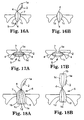
- Figures 12 to 15 show how the cord 5 of Figure 3 can be used in place of the cord 6 to mask a gap 7 between two parts (8, 9) or (8, 10) or (10, 12) of a vehicle to protect an A-post 11 ( Figure 12), B-post 13 ( Figures 13 and 14), and a C-post ( Figure 15).
- the cord 5 is shown attached to a surface inside the gap 7 using the adhesive stripe 2 as shown and arranged to mask the gap 7 to allow blending across the gap 7 if required or to protrude from the gap 7 if blending is not required.
- cord 5 could be located and secured in position by wedging in the gap 7 and optionally securing to a surface outside the gap 7 using the adhesive stripe 2 as described previously for the cord 6.
- the layer 1a may be released along one side of the cord 5 and used to hold the cord 5 when inserting and feeding the cord 5 along the gap 7, pulling the cord 5 into the gap to wedge it in place as shown in Figure 16A and then removing the layer 1a if desired as shown in Figure 16B.
- the multiple layers 1a, 1b, 1c of foam web enable the cords 5, 6 to be adapted to provide different thicknesses of masking material for masking across gaps in a range of sizes and locations.
- the same cord 5, 6 may therefore be used where previously several different cords were required to mask across gaps of different sizes and/or in different locations.
- cord 5 shown in Figure 5A can be adapted to provide a required thickness of masking material for different sizes of gap 7 by removing one or more foam strips as shown in Figures 17A, 17B.
- cord 6 shown in Figure 5B can be adapted to provide a required thickness of masking material for different sizes of gap 7 by superimposing the appropriate number of foam strips as shown in Figures 18A, 18B.
- a further advantage of forming the cords from multiple layers 1a, 1b, 1c of foam web is that the cords 5, 6 may be used more than once. For example, after painting, any foam layer of cord 5 that has been painted may be removed to reveal an underlying clean foam layer. Likewise, after painting, any foam layer of cord 6 that has been painted may be removed or, alternatively, the foam layers may be folded in a different configuration to conceal the painted foam layer.
- the extent to which the cords 5, 6 can be re-used may depend on the number and/or thickness of the foam layers forming the initial cord 5, 6 and thus, the range of sizes that can be obtained by different combinations of the foam layers.
- a large number of relatively thin foam layers may provide more options than a small number of relatively thick foam layers.
- foam layers of different thickness may be provided in different colours to assist identification and selection of the appropriate combination of foam layers to produce a desired overall thickness of cord 5, 6.
- Adhesive stripes may also be provided on more than one foam layer of the cords 5, 6.
- each foam layer in the finished cord 5, 6 may have an adhesive stripe. This may allow the cord 5, 6 to be stuck to more than one surface in use. Alternatively or additionally, after use, the foam layer used to stick the cord to a surface may be removed to reveal a foam layer with a fresh adhesive stripe for sticking the cord when re-using the masking material.
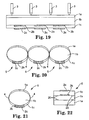
- FIGs 19 to 21 show a cord 5 and method of producing the cord 5 similar to Figures 1 to 3 but in which the removable outer layers 1a, 1c are of different thickness to the centre or core layer 1b.
- three superimposed layers 1a, 1b, 1c of foam web are cold welded to produce an array of longitudinally extending, parallel cords 5 joined together by cold weld seams 4 as before.
- the outer layers 1a, 1c are of the same thickness and the centre layer 1b is of substantially greater thickness than the combined thickness of the layers 1a, 1c.
- an adhesive stripe 2b is provided on the surface of layer 1b facing outer layer 1c in addition to the adhesive stripe 2c on the outer surface of layer 1c.
- the foam cord 5 may be secured with the adhesive stripe 2c of the outer layer 1c to mask across a gap as described previously.
- the outer layers 1a, 1c can be removed to expose the clean surfaces on both sides of the centre layer 1b.
- the cord 5 can then be re-used to mask across a gap by securing in position with the adhesive stripe 2b of the centre layer 1b.
- the cord 5 can be stored without removing the outer layers 1a, 1c so that the clean surfaces of the centre layer 1b are protected beneath the outer layers 1a, 1c until it is desired to re-use the cord 5.
- the cord 5 may have portions of different colour, for example the layer 1a may be a light coloured foam and the layer 1c a dark coloured foam, such that a colour contrast is produced at each side edge of the cord 5 creating a longitudinal sight line which may be used to facilitate accurate positioning of the cord 5.
- a colour contrast between portions of the cord 5 may also be employed to provide a longitudinal sight line between the side edges of the cord 5 on one or both faces of the cord 5 to assist accurate positioning of the cord 5.
- the colour contrast may be produced by any suitable method and may be repeated for any underlying layers on re-use of the cord 5 if the outer layers are removed.
- foam cords 5 may be produced having a centre layer with one or more removable outer layers on each side and in any combination of thicknesses.
- a centre layer of substantially greater thickness than the removable outer layers there is only a small reduction in the thickness of the cord 5 on each re-use.
- the thickness of the removable outer layers may be chosen to produce a desired reduction in thickness of the cord 5 when the outer layers are removed. For example, we may produce a cord 5 having a centre layer 13mm thick and an outer layer 3mm thick on each side such that the cord 5 has an initial thickness of 19mm which is reduced to 13mm for re-use when the outer layers are removed.
- n-1 uses if the outer layers on both sides are removed after each use.
- cross-contamination from any painted layer is not a problem it may only be necessary to remove one of the layers to expose a new adhesive stripe to secure the cord in position.
- there are n uses if there are n layers with adhesive in the original cord, there are n uses if an adhesive bearing layer is removed before each re-use.
- a release coat (not shown) may be applied to the inner surface of the outer layer to reduce or prevent adhesion of this layer to the adhesive stripe of the underlying inner layer. In this way, removal of the outer layer is facilitated.
- release coats are well known to those skilled in the art and are typically referred to as LAB's (Low Adhesion Backsize).
- a non-stick liner or laminate may be incorporated between the outer layer and the underlying inner layer to facilitate removal of the outer layer.
- Such liner or laminate may be incorporated during the cold welding process for producing the multi-layer masking material.
- the outer layer may be sculpted or otherwise shaped on the inner surface to minimise contact with the opposed adhesive stripe of the underlying inner layer to facilitate removal of the outer layer.
- FIG 22 shows an example of a cord formed from three superimposed layers 1a, 1b, 1c of foam secured together by adhesive strips 20 along both side edges of the cord. These strips 20 may have a low tack so as to hold the layers 1a, 1b, 1c together but allow the layers 1a, 1c to be removed without damaging the underlying layer 1b. This construction may permit cords to be produced having any desired cross-section.
Abstract
Description
- This invention concerns improvements in or relating to foam articles. The invention has particular, but not exclusive, application to foam articles for use as masking materials when painting part of a vehicle to protect another part of the vehicle so that paint is only applied to the selected part of the vehicle. The invention also concerns a method of manufacturing such foam articles.
- More specifically, the invention relates to foam articles for use as masking materials to block temporarily a gap between two parts of a vehicle to prevent paint entering the gap when the vehicle is being spray painted. The foam articles of this invention are especially suitable for use in vehicle body shops when respraying part of a vehicle following a repair.
- It is already known to use masking materials in the form of an elongate foam strip to fill the gap between a movable part of the vehicle such as a door, hood or trunk and an adjacent part of the vehicle. Typically the foam strip has a longitudinally extending stripe of pressure sensitive adhesive by means of which the foam strip can be secured in the required position prior to painting and subsequently removed after painting.
- The size and shape of the gap, and the available surface for mounting the foam strip may vary according to the position of the gap. For example, in a vehicle, the "A" post is the pillar situated between the vehicle body and the front edge of the front door, the "B" post is the pillar situated between the rear edge of the front door and the front edge of the rear door, and the "C" post is the pillar situated between the rear edge of the rear door and the vehicle body.
- Typically, the "A" post supports the hinges for the front door, the "B" post supports the catch for the front door and the hinges for the rear door, and the "C" post supports the catch for the rear door. Often, a different type of foam strip is required to block the gap formed at each of these positions with each type of foam strip being provided in a range of sizes to accommodate variations in the dimensions of the gap between different makes or models of vehicle.
- As a result vehicle body shops have to stock many types of foam strips in a variety of sizes to cover all possible applications. This is expensive both in terms of the amount of stock required and the space required to store the stock.
- Furthermore, the user has to select and fit the correct type and size of foam strip for a given application, and use of the wrong foam strip may allow paint to penetrate the gap requiring corrective work to be carried out. This involves extra time and materials to complete a repair which reduces efficiency and profitability.
- A foam strip is disclosed in International Patent Application No. WO99/52646 assigned to the assignee of the present application having a generally elongate cross-section with rounded ends which can be used as a masking material in more than one position when painting a vehicle. In particular, the foam strip of this application can be used to mask the gap formed at the "A" or "B" post of a vehicle as well as the gap formed between the rear edge of the vehicle body and a tailgate.
- Such foam strip reduces the number of types of foam strip required for use at different positions of the vehicle and offers significant advantages and benefits to the user by allowing the same foam strip to be used in more than one location. The problem still remains however that a given thickness of foam strip may not be capable of masking gaps of different size and different thicknesses of foam strips may still be required for effective masking of these gaps.
- Moreover, the foam strips currently used as masking materials including the foam strip of WO99/52646 require access to the gap to be masked for securing the foam strip by means of the adhesive stripe and particular problems arise when masking the "A" post. Thus, there is only limited access to the gap in both the closed and open position of the door for inserting and sticking the foam strip to the appropriate surface. As a result, attaching the foam strip in the required position to mask across the gap when the door is closed is often a difficult and time consuming operation.
- Furthermore, the existing foam strips including the foam strip of WO99/52646 are only suitable for use once and, after painting, are removed and thrown away. Thus, on first use, the exposed portion of the foam strip is painted and the foam strip cannot be re-attached to conceal the painted portion and present a new, clean portion of the strip. As a result, re-use of the foam strip is at best unsatisfactory and is generally avoided.
- WO 99/46056 describes masking materials and method of use. A masking material comprises an elongate strip at least partially coated with a layer of a pressure-sensitive adhesive, the strip having a curved surface which is convex when the strip is viewed in cross section and is positioned such that when the strip is adhered to a substrate by the layer of pressure-sensitive adhesive a portion of the curved surface overhangs the substrate. The masking material comprises a removable edge portion comprising said portion of the curved surface detachably secured to a remainder of the strip and which may be removed to expose a second curved surface on the remainder of the strip which is convex when viewed in cross section and which is positioned to overhang the substrate.
- The present invention provides a foam article which can be used as a masking material having an even wider range of application for masking gaps of different types and different sizes than existing masking materials.
- Furthermore, the present invention provides a foam article for use as a masking material that is capable of being secured in position without the use of adhesive.
- Moreover, the present invention provides such a foam article for use as a masking material that can be used where access to a surface for adhesively securing the article is limited or restricted.
- Additionally, the present invention provides such a foam article for use as a masking material that can be used more than once.
- More specifically, the present invention provides a foam article, the manufacture of such article and the use thereof as a masking material to mask a gap when painting a vehicle which has generally universal application for masking gaps at different locations and in a range of sizes.
- In one aspect, the present invention provides a foam article for use as a masking material comprising at least three elongate foam strips, each strip having a longitudinally extending edge and being joined at said longitudinally extending edge to a longitudinally extending edge of at least one further elongate strip by a seam common to all said strips.
- By forming the foam article from at least three foam strips, the foam article can be adapted to provide masking material of the required thickness for use in any selected one of a range of different types and size of gap by the selection of the appropriate number of foam strips to mask the gap.
- Moreover, it may be possible to locate and retain the masking material without the use of adhesive by relying on the compression of the masking material through the selection of the appropriate number of foam strips to wedge the masking material in the gap.
- Furthermore, after use, the masking material can be re-used by arranging the foam strips to mask a gap with fresh or clean surfaces of the masking material exposed.
- Typically, each foam strip is of generally elongate cross-section having longitudinally extending edges on opposite sides of a longitudinally extending body portion.
- In one embodiment, the common seam joins all the foam strips along one side edge and the other side edge is free. In this way, the foam strips are secured longitudinally to radiate from said common seam. As a result, the foam strips can be arranged to superimpose different combinations of the foam strips to provide different thicknesses of masking material.
- Advantageously, the foam strips are separable along said common seam. In this way, any foam strips that are not required can be removed to leave the desired thickness of masking material.
- Furthermore, after use, any foam strips that are painted can be removed and the remaining foam strips arranged to provide masking material for another use.
- Removing any painted foam strips reduces the thickness of masking material that can be produced with the remaining foam strips. It may be possible to re-use the masking material without reducing the thickness by re-arranging the foam strips so that any painted foam strips are concealed by unpainted foam strips when the masking material is secured in position.
- In another embodiment, the common seam joins all the foam strips along one side edge and a further common seam joins all the foam strips along the other side edge. In this way, the foam strips are secured relative to each other in a superimposed relationship to provide masking material having a thickness corresponding substantially to the combined thickness of the individual foam strips.
- Advantageously, the foam strips are separable along said common seams. In this way, the outermost foam strips can be removed to vary the thickness of the masking material.
- Additionally, after use, any foam strips that are covered in paint can be removed and the remaining foam strips arranged to provide masking material for another use.
- In either construction, the number and/or thickness of the foam strips may be chosen to provide the masking material with any desired range of thicknesses by selecting an appropriate combination of foam strips.
- For example, the foam strips may all be of the same thickness or at least one foam strip may be of different thickness to the other foam strip(s). Generally, the foam strips are selected when combined to provide masking material having a maximum thickness of up to about 30mm.
- Furthermore, the foam material of the foam strips may be chosen to provide the masking material with any desired properties. For example, the foam strips may all be of the same type of foam material or at least one foam strip may be of a different type of foam material.
- Typically, the foam material employed may be an open or closed cell polymeric foam that is resiliently compressible for conforming to a required shape for a given application. Foams having a density in the range of from 20 to 30Kg/m3 are generally found to be useful for use as masking materials.
- The foam strips may all be of the same colour. Alternatively, different properties or characteristics of the foam strips such as thickness or type of foam material, may be distinguished by different colours or combinations of colours. Colour coding the foam strips in this way has advantages for both the manufacture and use of masking materials with the appropriate combination of foam strips for the required application.
- Different colours may also be used to provide a colour contrast de-limiting a sight line at the boundary between differently coloured portions of the foam strips to assist in accurately positioning the masking material.
- Typically, the foam strips are made of cold weldable material. In this way, the foam article may be produced by forming a cold weld seam along at least one side edge of the foam strips. Preferred foam materials include polystyrene, polyvinylchloride, polyethylene, polyurethane, polyisocyanate, polyphenol, polyester and silicone foams.
- The foam material may be cold welded by applying pressure to superimposed layers of foam web with a former such as a rotatable pressure roller or wheel so as to compress the layers of foam web sufficiently to cause the foam layers to fuse together.
- A cold weld seam formed in this way unites the layers of foam material to each other along the seam and allows individual layers to be separated from the other layers which remain united along the seam.
- The foam articles may be provided with a longitudinal adhesive stripe on at least one foam strip for sticking the foam article in position. Preferred adhesives are pressure sensitive adhesives such as a hot melt rubber adhesive. The adhesive may be applied to the foam by any suitable means, for example die coating, before or after the cold welding operation.
- In another aspect, the present invention provides a method of manufacturing a foam article for use as a masking material including the steps of providing at least three sheets of foam material, superimposing the sheets of foam material, joining the sheets of foam material at a plurality of spaced positions by longitudinally extending parallel seams, and separating the sheets of foam material along the seams to produce a plurality of elongate foam articles, wherein each foam article comprises at least three foam strips joined together by at least one seam a side edge of the foam strips.
- The foam article produced by the above method may have the foam strips joined together along both side edges so that the foam strips are secured in superimposed relationship to each other. This form of the foam article can be used as a masking material and can be adapted to a required thickness of masking material for a given application by removing one or more of the foam strips.
- Alternatively, the foam strips may be joined together along one side edge only so that the foam strips radiate from the seam. This form of the foam article can also be used as a masking material and can be adapted to any desired thickness by superimposing the appropriate number of foam strips.
- Typically, the foam material is cold weldable and the seams are formed by compressing the sheets of foam material to fuse the sheets together along the seams. The cold welding operation may be effected by a former such as a rotary pressure wheel or roller and a plurality of seams may be formed simultaneously by arranging a series of formers transversely spaced across the superimposed sheets of foam material.
- In one method, the foam strips are joined together by cold weld seams along both side edges when the sheets of foam material are separated to produce one form of foam article, and the seam along one side edge can be optionally ruptured if it is desired to produce another form of foam article. In this way, both forms of the foam article each comprising at least three foam strips can be produced by the same method.
- By forming the foam article with cold weld seams along one or both side edges of the foam strips, the foam strips can be arranged to provide any required thickness of masking material for a given application as described previously and, after use, the arrangement of the foam strips can be adapted so that the masking material can be re-used.
- For example, where the foam strips are joined along both side edges, any painted foam strips may be removed to expose a new, unpainted foam strip below for re-use of the masking material.
- Similarly, where the foam strips are joined along one side edge, any painted foam strips may be removed leaving the remaining new, unpainted foam strips for re-use of the masking material.
- Alternatively, where the foam strips are joined along one side edge, the foam strips may be folded and superimposed in a different orientation so that the painted foam strips are concealed for re-use of the masking material.
- The options and variations for altering and adapting the masking material for re-use are numerous and will be understood by those skilled in the art.
- Thus, in another embodiment of the foam article for use as a masking material, the arrangement of the foam strips can be adapted to enable the foam article to be re-used.
- By releasably securing the foam strips, any foam strip that has been painted when the foam article is used as a masking material can be removed so as to leave new, unpainted foam strips for further use of the foam article as a masking material.
- The foam articles of the present invention are particularly suited for use in masking a gap between two parts of a vehicle such as a door and the vehicle body or two doors. Thus, the foam article can be adapted to a range of gap sizes by selecting the combination of the individual foam strips to vary the thickness of the foam article.
- Thus, in another embodiment of the foam article for use as a masking material, the arrangement of the foam strips can be adapted to vary the thickness of the foam article.
- Although not part of the present invention, a method can be considered of masking a gap between two parts of a vehicle when painting at least one of the parts, the method comprising the steps of providing an elongate foam article comprising a plurality of elongate foam strips joined together by a seam along at least one side edge, and positioning the foam article to mask the gap.
- The method may include the step of selecting a combination of foam strips to adapt the thickness of foam article to the gap to be masked.
- The method may also include the step of wedging the selected combination of foam strips in the gap without the use of adhesive.
- Wedging the selected combination of foam strips in position may be of particular benefit if access to the gap is limited or restricted, for example when masking an "A" post. Thus, the selected combination of foam strips may be positioned in the gap and pulled through to wedge in the gap without the use of adhesive to secure the foam strip inside the gap.
- In yet a further embodiment, the foam article for use as a masking material comprises a plurality of superimposed foam strips releasably secured together.
- The foam strips may be secured together by cold welding or adhesive or any other suitable method that allows selective removal of one or more foam strips. In this way, different thicknesses of masking material can be obtained and/or, after use, contaminated foam strips can be removed to expose fresh strips allowing the masking material to be re-used.
- Other features, benefits and advantages of the invention in each of its aspects will be more readily understood from the description hereinafter of exemplary embodiments in which like reference numerals are used throughout to indicate corresponding parts.
- The invention will now be described in more detail by way of example only with reference to the accompanying drawings in which like reference numerals are used to indicate corresponding parts.
-
- Figure 1 shows a method of manufacturing foam articles embodying the present invention;
- Figure 2 shows a section through a plurality of foam articles produced by the method of Figure 1;
- Figure 3 shows a section through one of the foam articles shown in Figure 2;
- Figure 4 shows a section through another foam article produced from the foam article shown in Figure 3;
- Figures 5A, 5B show modifications of the foam articles shown in Figures 3 and 4;
- Figures 6A, 6B shows another modification of the foam articles shown in Figures 3 and 4;
- Figures 7A, 7B shows a further modification of the foam articles shown in Figures 3 and 4;
- Figures 8A, 8B shows a still further modification of the foam articles shown in Figures 3 and 4;
- Figures 9A to 9D show the application of the foam article shown in Figure 4 as a masking material to mask an A-post;
- Figures 10A, 10B show the application of the foam article shown in Figure 4 as a masking material to mask a B-post;
- Figures 11A, 11B show the application of the foam article shown in Figure 4 as a masking material to mask a C-post;
- Figure 12 shows the application of the foam article shown in Figure 3 as a masking material to mask an A-post;
- Figure 13 shows the application of the foam article shown in Figure 3 as a masking material to mask a B-post;
- Figure 14 shows an alternative application of the foam article shown in Figure 3 as a masking material to mask a B-post;
- Figure 15 shows the application of the foam article shown in Figure 3 as a masking material to mask a C-post;
- Figures 16A, 16B shows an alternative application of the foam article shown in Figure 3 as a masking material;
- Figures 17A, 17B show the application of the foam article shown in Figure 5A as a masking material to mask gaps of different size;
- Figures 18A, 18B show the application of the foam article shown in Figure 5B as a masking material to mask gaps of different size; and
- Figure 19 is a view similar to Figure 1 showing the method of manufacturing foam articles according to another embodiment of the invention;
- Figure 20 is a view similar to Figure 2 showing a section through a plurality of foam articles produced by the method of Figure 19;
- Figure 21 is a view similar to Figure 3 showing a section through one of the foam articles shown in Figure 20; and
- Figure 22 shows a section through another foam article embodying the invention.
- Referring first to Figure 1, a foam article for use as a masking material embodying the present invention is made by cold welding at least three superimposed layers of foam web or sheet. In this example, three
layers - The
layers layer - The selection of the type of foam depends on the requirements and intended application of the masking material and the above examples of suitable materials are not intended to be limiting on the scope of this invention. Other types of foams may be employed where appropriate as will be appreciated by those skilled in the art.
- In this embodiment, each
layer layers layers - As shown the upper layer la is provided with a plurality of spaced,
parallel stripes 2 of an adhesive capable of adhering to the foam material. Suitable adhesives include pressure sensitive adhesives such as hot melt rubber adhesives that can be applied by die coating. Again, the selection and composition of the adhesive depends on the requirements and intended application of the masking material. - In this embodiment, the
adhesive stripes 2 are applied to the foam web of theupper layer 1 a prior to joining thelayers adhesive stripes 2 could be provided at any stage in the manufacture of the foam articles. Furthermore,adhesive stripes 2 could be applied to any of the foam webs forming thelayers stripes 2 depends on the requirements and intended application of the masking material. - The
layers wheels 3 spaced apart a pre-determined distance to form a plurality of spaced,parallel seams 4 extending longitudinally of the webs. Therollers 3 compress thelayers layers - In this embodiment, the spacing between the
seams 4 is about 20mm but this may be altered to suit the requirements and intended application of the masking material. - Figure 2 shows the
layers parallel foam cords 5 joined by the cold weld seams 4. - The
foam cords 5 are separable from each other along theseams 4 either manually or by a suitable cutting device (not shown) and may be stored and supplied in rolls of pre-determined length wound on itself or a core (not shown) from which the user can unwind and separate a required length. - More than one
foam cord 5 of the same or different size may be wound on a common core. Wherecords 5 of the same size are provided on a common core, these may be provided separately or joined together by the cold weld seams 4 and manually separated by the user when unwinding a required length of the selectedcord 5. - Figure 3 shows a
single foam cord 5 separated from the array offoam cords 5 illustrated in Figure 2. Thefoam cord 5 has a generally elliptical shape in which thelayers - The shape of the
foam cord 5 will depend on a number of factors including the thickness of thelayers layers - The
foam cord 5 shown in Figure 3 may be used in this form as a masking material when painting a vehicle to mask a gap between two parts of a vehicle to prevent paint entering the gap as described later herein. - Alternatively, the
foam cord 5 shown in Figure 3 may be converted to another form shown in Figure 4 by opening thecold weld seam 4 along one side edge of thefoam layers foam cord 6 in which thefoam layers cold weld seam 4 along the other side edge only. - This alternative form of the
foam cord 6 may also be used as a masking material when painting a vehicle to mask a gap between two parts of a vehicle to prevent paint entering the gap as described later herein. - Some modifications illustrating the scope of the invention are shown.in Figures 5 to 8 which show how the number and/or thickness of the layers of the
cords cords - Figures 5A,
5B show cords layers 6B show cords layers 7B show cords adhesive stripe 2 is provided on eachlayer 8B show cords layer 1a is of different colour to thelayers layers - These examples are illustrative only of different possible constructions of the
cords - Various examples of the application of the
foam cord 6 shown in Figure 4 as masking materials are now described with reference to Figure 9 to 11. - Figures 9A, 9B, 9C, 9D show the use of the star-shaped
foam cord 6 of Figure 4 to mask agap 7 between thefront edge 8a of a vehiclefront door 8 and anadjacent edge 9a of abody part 9 such as a front wing to protect the A-post 11 when painting thedoor 8 and/orbody part 9. - The
foam cord 6 is held by the foam layer la having theadhesive stripe 2. Thedoor 8 is opened and theother foam layers gap 7. Thedoor 8 is then gently closed and thefoam cord 6 fed along the length of thegap 7 by pulling through with the protrudinglayer 1a as shown in Figure 9A. - If blending across the
gap 7 between thedoor 8 andpart 9 is not required, thefoam cord 6 is secured by folding down the layer la and sticking to thepart 9 using theadhesive stripe 2 as shown in Figure 9B when painting thedoor 8. The orientation of thefoam cord 6 may be reversed to stick thelayer 1 a to thedoor 8 when painting thepart 9. - If blending across the
gap 7 is required when painting both thedoor 8 andpart 9, thefoam cord 6 is pulled up so as to wedge thelayers gap 7 as shown in Figure 9C. Thelayer 1a is then removed by separating along thecold weld seam 4 as shown in Figure 9D. Thecord 6 remains in place due to the friction wedging thelayers gap 7. - Figures 10A, 10B show the use of the star-shaped
cord 6 of Figure 4 to mask agap 7 between therear edge 8b of a vehiclefront door 8 and thefront edge 10a of a vehiclerear door 10 to protect the B-post 13 when painting thedoor 8 and/ordoor 10. - The
front door 8 is opened and thecord 6 secured by sticking thelayer 1a to either the B-post 13 (Figure 10A) or the inside of the door 8 (Figure 10B) with theadhesive stripe 2. - If the
layer 1a is attached to the B-post 13 as shown in Figure 10A, thelayers layer 1a and held in place when thedoor 8 is closed. Thecord 6 masks thegap 7 and allows blending across thegap 7. - If desired, the
layer 1c adjacent to thedoor 8 may have an adhesive stripe 2' as indicated in dotted lines to adhere to the inside of theclosed door 8. The adhesive stripe 2' may be applied to thelayer 1c prior to cold welding to join thelayers - If the
layer 1a is attached to the inside of thedoor 8 as shown in Figure 10B, one or both of thelayers gap 7 when thedoor 8 is closed. Any protrudinglayer gap 7 is not required or pushed back into thegap 7 if blending across thegap 7 is required. - Figures 11A, 11B show the use of the star-shaped
cord 6 of Figure 4 to mask agap 7 between therear edge 10b of arear door 10 and abody part 12 such as a rear wing to protect a C-post when painting thedoor 10 and/orpart 12. - The
rear door 10 is opened and thecord 6 secured by sticking the layer la to thebody part 12 with theadhesive stripe 2. - The
layers layer 1a and held in place when thedoor 10 is shut. Thecord 6 masks thegap 7 while allowing blending across thegap 7 as shown in Figure 11A. - If desired, the
layer 1c adjacent to thedoor 10 may be provided with an adhesive stripe 2' as shown in dotted line to adhere to thedoor 10. The stripe 2' maybe applied to thelayer 1c prior to cold welding thelayers - If blending across the
gap 7 is not required, one of thelayers gap 7 and used to mask up to the edge ofgap 7 on one side either by securing the protruding layer with masking tape or by providing this layer with an adhesive stripe 2' for sticking to the appropriate surface as shown in Figure 11B. - The above examples illustrate alternative ways of locating and securing the
cord 6. Thus, thecord 6 can be adhesively secured to a surface inside the gap to be masked when a suitable surface is readily accessible by opening a door or similar movable panel such as when protecting the B-post 13 or C-post of a vehicle. - Alternatively, when access to a surface inside the
gap 7 is restricted, thecord 6 can be wedged in the gap without the use of adhesive or adhesively secured to a surface outside the gap such as when protecting the A-post 11 of a vehicle. - Of course, it will be appreciated that wedging the
cord 6 in thegap 7 or adhesively securing the cord to a surface outside thegap 7 could also be employed in locations where surfaces inside thegap 7 are accessible, for example when protecting the B-post 13 or C-post of a vehicle. - Referring now to Figures 12 to 15, these show how the
cord 5 of Figure 3 can be used in place of thecord 6 to mask agap 7 between two parts (8, 9) or (8, 10) or (10, 12) of a vehicle to protect an A-post 11 (Figure 12), B-post 13 (Figures 13 and 14), and a C-post (Figure 15). - In each of these examples, the
cord 5 is shown attached to a surface inside thegap 7 using theadhesive stripe 2 as shown and arranged to mask thegap 7 to allow blending across thegap 7 if required or to protrude from thegap 7 if blending is not required. - It will be appreciated however, that the
cord 5 could be located and secured in position by wedging in thegap 7 and optionally securing to a surface outside thegap 7 using theadhesive stripe 2 as described previously for thecord 6. - For this, the
layer 1a may be released along one side of thecord 5 and used to hold thecord 5 when inserting and feeding thecord 5 along thegap 7, pulling thecord 5 into the gap to wedge it in place as shown in Figure 16A and then removing thelayer 1a if desired as shown in Figure 16B. - The foregoing examples illustrates the versatility of both forms of the
foam cord multiple layers - In particular, the
multiple layers cords same cord - For example, the
cord 5 shown in Figure 5A can be adapted to provide a required thickness of masking material for different sizes ofgap 7 by removing one or more foam strips as shown in Figures 17A, 17B. - Similarly, the
cord 6 shown in Figure 5B can be adapted to provide a required thickness of masking material for different sizes ofgap 7 by superimposing the appropriate number of foam strips as shown in Figures 18A, 18B. - It will be appreciated, however, that many different combinations of the number of foam layers and/or the thickness of individual foam layers may be employed in which all the layers may be of the same thickness or one or more foam layers may be of different thickness to the other layers. All combinations of the number and/or thickness of the individual foam layers forming the cords are within the scope of the present invention.
- A further advantage of forming the cords from
multiple layers cords cord 5 that has been painted may be removed to reveal an underlying clean foam layer. Likewise, after painting, any foam layer ofcord 6 that has been painted may be removed or, alternatively, the foam layers may be folded in a different configuration to conceal the painted foam layer. - The extent to which the
cords initial cord - Where foam layers of different thickness are employed, these may be provided in different colours to assist identification and selection of the appropriate combination of foam layers to produce a desired overall thickness of
cord - Adhesive stripes may also be provided on more than one foam layer of the
cords finished cord cord - Referring now to Figures 19 to 21, these show a
cord 5 and method of producing thecord 5 similar to Figures 1 to 3 but in which the removableouter layers core layer 1b. - In this embodiment, three
superimposed layers parallel cords 5 joined together by cold weld seams 4 as before. Theouter layers centre layer 1b is of substantially greater thickness than the combined thickness of thelayers adhesive stripe 2b is provided on the surface oflayer 1b facingouter layer 1c in addition to theadhesive stripe 2c on the outer surface oflayer 1c. - In use, the
foam cord 5 may be secured with theadhesive stripe 2c of theouter layer 1c to mask across a gap as described previously. After use, theouter layers centre layer 1b. Thecord 5 can then be re-used to mask across a gap by securing in position with theadhesive stripe 2b of thecentre layer 1b. Before re-use, thecord 5 can be stored without removing theouter layers centre layer 1b are protected beneath theouter layers cord 5. - The
cord 5 may have portions of different colour, for example thelayer 1a may be a light coloured foam and thelayer 1c a dark coloured foam, such that a colour contrast is produced at each side edge of thecord 5 creating a longitudinal sight line which may be used to facilitate accurate positioning of thecord 5. A colour contrast between portions of thecord 5 may also be employed to provide a longitudinal sight line between the side edges of thecord 5 on one or both faces of thecord 5 to assist accurate positioning of thecord 5. The colour contrast may be produced by any suitable method and may be repeated for any underlying layers on re-use of thecord 5 if the outer layers are removed. - It will be appreciated that
foam cords 5 may be produced having a centre layer with one or more removable outer layers on each side and in any combination of thicknesses. By providing a centre layer of substantially greater thickness than the removable outer layers, there is only a small reduction in the thickness of thecord 5 on each re-use. Alternatively, the thickness of the removable outer layers may be chosen to produce a desired reduction in thickness of thecord 5 when the outer layers are removed. For example, we may produce acord 5 having a centre layer 13mm thick and an outer layer 3mm thick on each side such that thecord 5 has an initial thickness of 19mm which is reduced to 13mm for re-use when the outer layers are removed. - In general, it can be seen that for a cord consisting of n layers, there are n-1 uses if the outer layers on both sides are removed after each use. In some cases, however, if cross-contamination from any painted layer is not a problem it may only be necessary to remove one of the layers to expose a new adhesive stripe to secure the cord in position. In this case, if there are n layers with adhesive in the original cord, there are n uses if an adhesive bearing layer is removed before each re-use. For some applications, it may even be possible to re-use the cord without removing any of the layers. Accordingly, it can be seen that the multi-layer construction of the cord provides many options for the application and use of the cord.
- Where an adhesive stripe for securing the cord is provided between two superimposed layers of the cord, a release coat (not shown) may be applied to the inner surface of the outer layer to reduce or prevent adhesion of this layer to the adhesive stripe of the underlying inner layer. In this way, removal of the outer layer is facilitated. Such release coats are well known to those skilled in the art and are typically referred to as LAB's (Low Adhesion Backsize).
- Alternatively, a non-stick liner or laminate (not shown) may be incorporated between the outer layer and the underlying inner layer to facilitate removal of the outer layer. Such liner or laminate may be incorporated during the cold welding process for producing the multi-layer masking material.
- Alternatively, the outer layer may be sculpted or otherwise shaped on the inner surface to minimise contact with the opposed adhesive stripe of the underlying inner layer to facilitate removal of the outer layer.
- Other modifications and variations will be apparent to those skilled in the art. For example, although we have described constructions of foam cord in which superimposed layers of foam are secured by cold weld seams along both sides edges of the cord, it will be appreciated that similar constructions could be made using adhesive strips instead of cold welds to hold the layers together. Figure 22 shows an example of a cord formed from three superimposed
layers adhesive strips 20 along both side edges of the cord. Thesestrips 20 may have a low tack so as to hold thelayers layers underlying layer 1b. This construction may permit cords to be produced having any desired cross-section. - It will be understood that the above-described examples are intended to illustrate the diverse range and application of the invented foam articles and that features of the embodiments may be used separately or in combination with any other feature of the same or different embodiments to produce a foam article that can be used as a masking material.
- Moreover, while the specific materials and/or configuration of the foam articles described and illustrated are believed to represent the best means currently known to the applicant for producing foam articles having application as multi-purpose masking materials, it will be appreciated that the invention is not limited thereto and that various modifications and improvements can be made within the scope of the appended claims.
Claims (25)
- A foam article for use as a masking material comprising at least three elongate foam strips, each strip having a longitudinally extending edge and being joined at said longitudinally extending edge to a longitudinally extending edge of at least one further elongate strip by a seam common to all said strips.
- A foam article according to claim 1 wherein each foam strip is of generally elongate cross-section having longitudinally extending edges on opposite sides of a longitudinally extending body portion.
- A foam article according to claim 2 wherein said common seam joins all the foam strips along one side edge and the other side edge is free.
- A foam article according to claim 3 wherein the foam strips are separable along said common seam.
- A foam article according to claim 2 wherein said common seam joins all the foam strips along one side edge and a further common seam joins all the foam strips along the other side edge.
- A foam article according to claim 5 wherein the foam strips are separable along said common seams.
- A foam article according to claim 1 wherein at least one foam strip is of different thickness to at least one other foam strip.
- A foam article according to claim 1 wherein the foam strips have a combined thickness of up to 30mm.
- A foam article according to claim 1 wherein at least one foam strip is made of a different foam material to at least one other foam strip.
- A foam article according to claim 1 wherein the foam strips are made of an open cell foam material.
- A foam article according to claim 1 wherein at least one foam strip is of different colour to at least one other foam strip.
- A foam article according to claim 1 wherein the foam strips are made of cold weldable material.
- A foam article according to claim 1 wherein at least one foam strip has a longitudinally extending adhesive stripe.
- A foam article according to claim 1 whereby, in use of the foam article as a masking material, the arrangement of the foam strips are adapted to enable the foam article to be re-used.
- A foam article according to claim 1 whereby, in use of the foam article as a masking material, the arrangement of the foam strips are adapted to vary the thickness of the foam article.
- A foam article according to claim 1, wherein the foam strips are releasably secured together.
- A foam article as claimed in Claim 16 wherein the foam strips are secured together by cold welding.
- A foam article as claimed in Claim 16 wherein the foam strips are secured together by adhesive.
- A foam article as claimed in Claims 16 to 18 wherein one or more of the foam strips is of different thickness to the other foam strips.
- A foam article as claimed in any one of Claims 16 to 18 comprising a centre foam strip and one or more removable foam strips on each side.
- A method of manufacturing a foam article for use as a masking material including the steps of providing at least three sheets of foam material, superimposing the sheets of foam material, joining the sheets of foam material at a plurality of spaced positions by longitudinally extending parallel seams, and separating the sheets of foam material along the seams to produce a plurality of elongate foam articles, wherein each foam article comprises at least three foam strips joined together by at least one seam a side edge of the foam strips.
- A method according to claim 21 wherein the foam strips are joined together along both side edges so that the foam strips are secured in superimposed relationship to each other.
- A method according to claim 21 wherein the foam strips are joined together along one side edge only so that the foam strips radiate from the seam.
- A method according to clam 21 wherein the foam material is cold weldable and the seams are formed by compressing the sheets of foam material to fuse the sheets together along the seams.
- A method according to claim 21 wherein a longitudinal adhesive stripe is provided on at least one foam strip of each foam article.
Applications Claiming Priority (3)
| Application Number | Priority Date | Filing Date | Title |
|---|---|---|---|
| GBGB0109177.6A GB0109177D0 (en) | 2001-04-12 | 2001-04-12 | Improvements in or relating to foam articles |
| GB0109177 | 2001-04-12 | ||
| PCT/US2002/011307 WO2002083392A1 (en) | 2001-04-12 | 2002-04-12 | Improved foam masking device |
Publications (2)
| Publication Number | Publication Date |
|---|---|
| EP1377425A1 EP1377425A1 (en) | 2004-01-07 |
| EP1377425B1 true EP1377425B1 (en) | 2006-08-23 |
Family
ID=9912751
Family Applications (1)
| Application Number | Title | Priority Date | Filing Date |
|---|---|---|---|
| EP02719481A Expired - Lifetime EP1377425B1 (en) | 2001-04-12 | 2002-04-12 | Improved foam masking device, and method of manufacturing such a device |
Country Status (12)
| Country | Link |
|---|---|
| US (1) | US6797361B2 (en) |
| EP (1) | EP1377425B1 (en) |
| JP (1) | JP3981016B2 (en) |
| AT (1) | ATE337151T1 (en) |
| AU (1) | AU2002250560B2 (en) |
| CA (1) | CA2443860C (en) |
| DE (1) | DE60214148T2 (en) |
| ES (1) | ES2271241T3 (en) |
| GB (1) | GB0109177D0 (en) |
| PT (1) | PT1377425E (en) |
| WO (1) | WO2002083392A1 (en) |
| ZA (1) | ZA200308776B (en) |
Families Citing this family (13)
| Publication number | Priority date | Publication date | Assignee | Title |
|---|---|---|---|---|
| US6596376B1 (en) * | 1999-03-09 | 2003-07-22 | 3M Innovative Properties Company | Masking materials and method of use |
| US20050006021A1 (en) * | 2001-04-12 | 2005-01-13 | 3M Innovative Properties Company | Foam articles |
| GB0109176D0 (en) * | 2001-04-12 | 2001-05-30 | 3M Innovative Properties Co | Masking material and a method of masking using same |
| AU2003249043A1 (en) * | 2002-07-13 | 2004-02-02 | 3M Innovative Properties Company | Patterned polymer articles |
| EP1426539B1 (en) * | 2002-12-05 | 2016-11-09 | Konrad Dipl.-Ing. Lehrhuber | Connecting section for a junction between a structural member and a building wall |
| GB0622340D0 (en) * | 2006-11-09 | 2006-12-20 | 3M Innovative Properties Co | Masking article |
| GB0711109D0 (en) * | 2007-06-11 | 2007-07-18 | 3M Innovative Properties Co | Masking article comprising skinned foam |
| USD751358S1 (en) | 2007-11-09 | 2016-03-15 | 3M Innovative Properties Company | Masking article |
| JP4568785B2 (en) | 2009-01-19 | 2010-10-27 | 株式会社神戸製鋼所 | Kneading rotor |
| GB201316765D0 (en) * | 2013-09-20 | 2013-11-06 | 3M Innovative Properties Co | Masking Tape |
| US9782788B2 (en) * | 2014-04-02 | 2017-10-10 | The Boeing Company | Method and system for forming masks |
| ES1139131Y (en) * | 2015-04-29 | 2015-08-10 | Bossauto Innova S A | BURLETE FOR BODIES |
| US11964292B2 (en) | 2021-03-17 | 2024-04-23 | David Rivera | Door hinge masking tape and method of use |
Family Cites Families (19)
| Publication number | Priority date | Publication date | Assignee | Title |
|---|---|---|---|---|
| US4484574A (en) * | 1984-01-25 | 1984-11-27 | Keene Corporation | Self-rolled foam tape without release layer and method of making same |
| US4698252A (en) * | 1984-04-26 | 1987-10-06 | Colamco, Inc. | Composite foam articles and method for fabricating such articles |
| US4996092A (en) | 1989-02-20 | 1991-02-26 | Minnesota Mining And Manufacturing Company | Shaped foam |
| GB2254812B (en) | 1991-04-19 | 1994-10-26 | Minnesota Mining & Mfg | Masking methods using flexible strip |
| DE4236948A1 (en) | 1992-11-02 | 1994-05-05 | Hoffmann Hans Guenter | Process as well as protective and masking tape for protecting and masking the rubber sealing strips of flush-mounted vehicle windows |
| US5354614A (en) | 1993-03-01 | 1994-10-11 | Minnesota Mining And Manufacturing Company | Masking tape with stiffened edge and method of gasket masking |
| GB9402812D0 (en) | 1994-02-14 | 1994-04-06 | Speedarrive Projects Limited | For a sealing strip |
| US5547725A (en) * | 1994-02-25 | 1996-08-20 | Tesa Tape Inc. | Production of a novel sculptured strip of plastic foam |
| GB2288137A (en) | 1994-03-08 | 1995-10-11 | Minnesota Mining & Mfg | Masking the "B" post of a vehicle using a foam strip |
| US5747094A (en) | 1996-01-29 | 1998-05-05 | Fibre Glass-Evercoat Company, Inc. | Method for checking paint applied to a surface |
| EP0795356B1 (en) | 1996-03-11 | 1999-05-26 | VOSSCHEMIE GmbH | Sealing and masking strips |
| JP3622931B2 (en) | 1996-04-04 | 2005-02-23 | ソニーケミカル株式会社 | Paint masking tape substrate and paint masking tape |
| DE29610642U1 (en) * | 1996-06-18 | 1996-10-02 | Voss Chemie | Foam strips |
| CA2235898C (en) | 1997-04-30 | 2006-08-15 | Sony Chemicals Corporation | Paint masking tape |
| GB2327052B (en) | 1997-09-10 | 1999-06-23 | Oliver Jevons | Masking tape and application method |
| GB9804967D0 (en) * | 1998-03-09 | 1998-05-06 | Minnesota Mining & Mfg | Masking materials and method of use |
| GB9807613D0 (en) | 1998-04-09 | 1998-06-10 | Minnesota Mining & Mfg | Masking material and method |
| GB9825591D0 (en) | 1998-11-24 | 1999-01-13 | Western Donald M | Device for masking and method |
| US20010005551A1 (en) | 1999-02-05 | 2001-06-28 | Paul Peter Siero | Striplike material for use with spraypainting |
-
2001
- 2001-04-12 GB GBGB0109177.6A patent/GB0109177D0/en not_active Ceased
-
2002
- 2002-04-12 JP JP2002581174A patent/JP3981016B2/en not_active Expired - Fee Related
- 2002-04-12 AU AU2002250560A patent/AU2002250560B2/en not_active Ceased
- 2002-04-12 DE DE60214148T patent/DE60214148T2/en not_active Expired - Lifetime
- 2002-04-12 ES ES02719481T patent/ES2271241T3/en not_active Expired - Lifetime
- 2002-04-12 AT AT02719481T patent/ATE337151T1/en not_active IP Right Cessation
- 2002-04-12 PT PT02719481T patent/PT1377425E/en unknown
- 2002-04-12 WO PCT/US2002/011307 patent/WO2002083392A1/en active IP Right Grant
- 2002-04-12 US US10/121,492 patent/US6797361B2/en not_active Expired - Fee Related
- 2002-04-12 CA CA2443860A patent/CA2443860C/en not_active Expired - Fee Related
- 2002-04-12 EP EP02719481A patent/EP1377425B1/en not_active Expired - Lifetime
-
2003
- 2003-11-11 ZA ZA200308776A patent/ZA200308776B/en unknown
Also Published As
| Publication number | Publication date |
|---|---|
| US6797361B2 (en) | 2004-09-28 |
| WO2002083392A1 (en) | 2002-10-24 |
| ES2271241T3 (en) | 2007-04-16 |
| JP2004530543A (en) | 2004-10-07 |
| AU2002250560B2 (en) | 2007-08-09 |
| ZA200308776B (en) | 2004-09-13 |
| EP1377425A1 (en) | 2004-01-07 |
| CA2443860C (en) | 2010-10-05 |
| ATE337151T1 (en) | 2006-09-15 |
| GB0109177D0 (en) | 2001-05-30 |
| CA2443860A1 (en) | 2002-10-24 |
| DE60214148T2 (en) | 2007-07-19 |
| DE60214148D1 (en) | 2006-10-05 |
| US20020160154A1 (en) | 2002-10-31 |
| PT1377425E (en) | 2007-01-31 |
| JP3981016B2 (en) | 2007-09-26 |
Similar Documents
| Publication | Publication Date | Title |
|---|---|---|
| EP1377425B1 (en) | Improved foam masking device, and method of manufacturing such a device | |
| AU2002250560A1 (en) | Improved foam masking device | |
| US6627259B1 (en) | Masking tapes and application methods | |
| ZA200501224B (en) | Masking strip | |
| EP0580766B1 (en) | Masking methods using flexible strip | |
| US20050006021A1 (en) | Foam articles | |
| EP1377388B1 (en) | Differently coloured masking material and a method of masking using same | |
| US6818251B2 (en) | Masking materials and method of use | |
| EP1069959A1 (en) | Foam strip for masking and method for masking a gap | |
| EP0749359B1 (en) | Masking method | |
| US6759089B2 (en) | Masking method | |
| JP2003527229A (en) | Masking tape and method for attaching the same | |
| WO1999046056A1 (en) | Masking materials and method of use |
Legal Events
| Date | Code | Title | Description |
|---|---|---|---|
| PUAI | Public reference made under article 153(3) epc to a published international application that has entered the european phase |
Free format text: ORIGINAL CODE: 0009012 |
|
| 17P | Request for examination filed |
Effective date: 20031024 |
|
| AK | Designated contracting states |
Kind code of ref document: A1 Designated state(s): AT BE CH CY DE DK ES FI FR GB GR IE IT LI LU MC NL PT SE TR |
|
| AX | Request for extension of the european patent |
Extension state: AL LT LV MK RO SI |
|
| 17Q | First examination report despatched |
Effective date: 20050426 |
|
| RTI1 | Title (correction) |
Free format text: IMPROVED FOAM MASKING DEVICE, AND METHOD OF MANUFACTURING SUCH A DEVICE |
|
| GRAP | Despatch of communication of intention to grant a patent |
Free format text: ORIGINAL CODE: EPIDOSNIGR1 |
|
| GRAS | Grant fee paid |
Free format text: ORIGINAL CODE: EPIDOSNIGR3 |
|
| GRAA | (expected) grant |
Free format text: ORIGINAL CODE: 0009210 |
|
| AK | Designated contracting states |
Kind code of ref document: B1 Designated state(s): AT BE CH CY DE DK ES FI FR GB GR IE IT LI LU MC NL PT SE TR |
|
| PG25 | Lapsed in a contracting state [announced via postgrant information from national office to epo] |
Ref country code: AT Free format text: LAPSE BECAUSE OF FAILURE TO SUBMIT A TRANSLATION OF THE DESCRIPTION OR TO PAY THE FEE WITHIN THE PRESCRIBED TIME-LIMIT Effective date: 20060823 Ref country code: IT Free format text: LAPSE BECAUSE OF FAILURE TO SUBMIT A TRANSLATION OF THE DESCRIPTION OR TO PAY THE FEE WITHIN THE PRESCRIBED TIME-LIMIT;WARNING: LAPSES OF ITALIAN PATENTS WITH EFFECTIVE DATE BEFORE 2007 MAY HAVE OCCURRED AT ANY TIME BEFORE 2007. THE CORRECT EFFECTIVE DATE MAY BE DIFFERENT FROM THE ONE RECORDED. Effective date: 20060823 Ref country code: LI Free format text: LAPSE BECAUSE OF FAILURE TO SUBMIT A TRANSLATION OF THE DESCRIPTION OR TO PAY THE FEE WITHIN THE PRESCRIBED TIME-LIMIT Effective date: 20060823 Ref country code: FI Free format text: LAPSE BECAUSE OF FAILURE TO SUBMIT A TRANSLATION OF THE DESCRIPTION OR TO PAY THE FEE WITHIN THE PRESCRIBED TIME-LIMIT Effective date: 20060823 Ref country code: CH Free format text: LAPSE BECAUSE OF FAILURE TO SUBMIT A TRANSLATION OF THE DESCRIPTION OR TO PAY THE FEE WITHIN THE PRESCRIBED TIME-LIMIT Effective date: 20060823 Ref country code: NL Free format text: LAPSE BECAUSE OF FAILURE TO SUBMIT A TRANSLATION OF THE DESCRIPTION OR TO PAY THE FEE WITHIN THE PRESCRIBED TIME-LIMIT Effective date: 20060823 Ref country code: BE Free format text: LAPSE BECAUSE OF FAILURE TO SUBMIT A TRANSLATION OF THE DESCRIPTION OR TO PAY THE FEE WITHIN THE PRESCRIBED TIME-LIMIT Effective date: 20060823 |
|
| REG | Reference to a national code |
Ref country code: GB Ref legal event code: FG4D |
|
| REG | Reference to a national code |
Ref country code: CH Ref legal event code: EP |
|
| REG | Reference to a national code |
Ref country code: IE Ref legal event code: FG4D |
|
| REF | Corresponds to: |
Ref document number: 60214148 Country of ref document: DE Date of ref document: 20061005 Kind code of ref document: P |
|
| PG25 | Lapsed in a contracting state [announced via postgrant information from national office to epo] |
Ref country code: DK Free format text: LAPSE BECAUSE OF FAILURE TO SUBMIT A TRANSLATION OF THE DESCRIPTION OR TO PAY THE FEE WITHIN THE PRESCRIBED TIME-LIMIT Effective date: 20061123 Ref country code: SE Free format text: LAPSE BECAUSE OF FAILURE TO SUBMIT A TRANSLATION OF THE DESCRIPTION OR TO PAY THE FEE WITHIN THE PRESCRIBED TIME-LIMIT Effective date: 20061123 |
|
| REG | Reference to a national code |
Ref country code: PT Ref legal event code: SC4A Free format text: AVAILABILITY OF NATIONAL TRANSLATION Effective date: 20061123 |
|
| NLV1 | Nl: lapsed or annulled due to failure to fulfill the requirements of art. 29p and 29m of the patents act | ||
| REG | Reference to a national code |
Ref country code: CH Ref legal event code: PL |
|
| ET | Fr: translation filed | ||
| REG | Reference to a national code |
Ref country code: ES Ref legal event code: FG2A Ref document number: 2271241 Country of ref document: ES Kind code of ref document: T3 |
|
| PLBE | No opposition filed within time limit |
Free format text: ORIGINAL CODE: 0009261 |
|
| STAA | Information on the status of an ep patent application or granted ep patent |
Free format text: STATUS: NO OPPOSITION FILED WITHIN TIME LIMIT |
|
| 26N | No opposition filed |
Effective date: 20070524 |
|
| PG25 | Lapsed in a contracting state [announced via postgrant information from national office to epo] |
Ref country code: GR Free format text: LAPSE BECAUSE OF FAILURE TO SUBMIT A TRANSLATION OF THE DESCRIPTION OR TO PAY THE FEE WITHIN THE PRESCRIBED TIME-LIMIT Effective date: 20061124 |
|
| PG25 | Lapsed in a contracting state [announced via postgrant information from national office to epo] |
Ref country code: IE Free format text: LAPSE BECAUSE OF NON-PAYMENT OF DUE FEES Effective date: 20070412 |
|
| PGFP | Annual fee paid to national office [announced via postgrant information from national office to epo] |
Ref country code: TR Payment date: 20080321 Year of fee payment: 7 |
|
| PG25 | Lapsed in a contracting state [announced via postgrant information from national office to epo] |
Ref country code: MC Free format text: LAPSE BECAUSE OF NON-PAYMENT OF DUE FEES Effective date: 20070430 |
|
| PG25 | Lapsed in a contracting state [announced via postgrant information from national office to epo] |
Ref country code: CY Free format text: LAPSE BECAUSE OF FAILURE TO SUBMIT A TRANSLATION OF THE DESCRIPTION OR TO PAY THE FEE WITHIN THE PRESCRIBED TIME-LIMIT Effective date: 20060823 Ref country code: LU Free format text: LAPSE BECAUSE OF NON-PAYMENT OF DUE FEES Effective date: 20070412 |
|
| PG25 | Lapsed in a contracting state [announced via postgrant information from national office to epo] |
Ref country code: TR Free format text: LAPSE BECAUSE OF NON-PAYMENT OF DUE FEES Effective date: 20090412 |
|
| REG | Reference to a national code |
Ref country code: FR Ref legal event code: PLFP Year of fee payment: 14 |
|
| PGFP | Annual fee paid to national office [announced via postgrant information from national office to epo] |
Ref country code: ES Payment date: 20150310 Year of fee payment: 14 |
|
| PGFP | Annual fee paid to national office [announced via postgrant information from national office to epo] |
Ref country code: PT Payment date: 20150407 Year of fee payment: 14 Ref country code: DE Payment date: 20150408 Year of fee payment: 14 Ref country code: GB Payment date: 20150408 Year of fee payment: 14 |
|
| PGFP | Annual fee paid to national office [announced via postgrant information from national office to epo] |
Ref country code: FR Payment date: 20150408 Year of fee payment: 14 Ref country code: IT Payment date: 20150420 Year of fee payment: 14 |
|
| REG | Reference to a national code |
Ref country code: DE Ref legal event code: R119 Ref document number: 60214148 Country of ref document: DE |
|
| GBPC | Gb: european patent ceased through non-payment of renewal fee |
Effective date: 20160412 |
|
| REG | Reference to a national code |
Ref country code: FR Ref legal event code: ST Effective date: 20161230 |
|
| PG25 | Lapsed in a contracting state [announced via postgrant information from national office to epo] |
Ref country code: DE Free format text: LAPSE BECAUSE OF NON-PAYMENT OF DUE FEES Effective date: 20161101 Ref country code: FR Free format text: LAPSE BECAUSE OF NON-PAYMENT OF DUE FEES Effective date: 20160502 Ref country code: GB Free format text: LAPSE BECAUSE OF NON-PAYMENT OF DUE FEES Effective date: 20160412 |
|
| PG25 | Lapsed in a contracting state [announced via postgrant information from national office to epo] |
Ref country code: PT Free format text: LAPSE BECAUSE OF NON-PAYMENT OF DUE FEES Effective date: 20161012 Ref country code: IT Free format text: LAPSE BECAUSE OF NON-PAYMENT OF DUE FEES Effective date: 20160412 |
|
| PG25 | Lapsed in a contracting state [announced via postgrant information from national office to epo] |
Ref country code: ES Free format text: LAPSE BECAUSE OF NON-PAYMENT OF DUE FEES Effective date: 20160413 |
|
| REG | Reference to a national code |
Ref country code: ES Ref legal event code: FD2A Effective date: 20180620 |