EP1060897B1 - Transportvorrichtung eines Aufzeichnungsträgers - Google Patents
Transportvorrichtung eines Aufzeichnungsträgers Download PDFInfo
- Publication number
- EP1060897B1 EP1060897B1 EP00112301A EP00112301A EP1060897B1 EP 1060897 B1 EP1060897 B1 EP 1060897B1 EP 00112301 A EP00112301 A EP 00112301A EP 00112301 A EP00112301 A EP 00112301A EP 1060897 B1 EP1060897 B1 EP 1060897B1
- Authority
- EP
- European Patent Office
- Prior art keywords
- belt
- recording medium
- roller
- recording
- transport belt
- Prior art date
- Legal status (The legal status is an assumption and is not a legal conclusion. Google has not performed a legal analysis and makes no representation as to the accuracy of the status listed.)
- Expired - Lifetime
Links
Images


Classifications
-
- B—PERFORMING OPERATIONS; TRANSPORTING
- B65—CONVEYING; PACKING; STORING; HANDLING THIN OR FILAMENTARY MATERIAL
- B65H—HANDLING THIN OR FILAMENTARY MATERIAL, e.g. SHEETS, WEBS, CABLES
- B65H5/00—Feeding articles separated from piles; Feeding articles to machines
- B65H5/02—Feeding articles separated from piles; Feeding articles to machines by belts or chains, e.g. between belts or chains
- B65H5/021—Feeding articles separated from piles; Feeding articles to machines by belts or chains, e.g. between belts or chains by belts
-
- B—PERFORMING OPERATIONS; TRANSPORTING
- B41—PRINTING; LINING MACHINES; TYPEWRITERS; STAMPS
- B41J—TYPEWRITERS; SELECTIVE PRINTING MECHANISMS, i.e. MECHANISMS PRINTING OTHERWISE THAN FROM A FORME; CORRECTION OF TYPOGRAPHICAL ERRORS
- B41J11/00—Devices or arrangements of selective printing mechanisms, e.g. ink-jet printers or thermal printers, for supporting or handling copy material in sheet or web form
- B41J11/007—Conveyor belts or like feeding devices
-
- B—PERFORMING OPERATIONS; TRANSPORTING
- B41—PRINTING; LINING MACHINES; TYPEWRITERS; STAMPS
- B41J—TYPEWRITERS; SELECTIVE PRINTING MECHANISMS, i.e. MECHANISMS PRINTING OTHERWISE THAN FROM A FORME; CORRECTION OF TYPOGRAPHICAL ERRORS
- B41J11/00—Devices or arrangements of selective printing mechanisms, e.g. ink-jet printers or thermal printers, for supporting or handling copy material in sheet or web form
- B41J11/0085—Using suction for maintaining printing material flat
-
- B—PERFORMING OPERATIONS; TRANSPORTING
- B65—CONVEYING; PACKING; STORING; HANDLING THIN OR FILAMENTARY MATERIAL
- B65H—HANDLING THIN OR FILAMENTARY MATERIAL, e.g. SHEETS, WEBS, CABLES
- B65H5/00—Feeding articles separated from piles; Feeding articles to machines
- B65H5/22—Feeding articles separated from piles; Feeding articles to machines by air-blast or suction device
- B65H5/222—Feeding articles separated from piles; Feeding articles to machines by air-blast or suction device by suction devices
- B65H5/224—Feeding articles separated from piles; Feeding articles to machines by air-blast or suction device by suction devices by suction belts
-
- B—PERFORMING OPERATIONS; TRANSPORTING
- B65—CONVEYING; PACKING; STORING; HANDLING THIN OR FILAMENTARY MATERIAL
- B65H—HANDLING THIN OR FILAMENTARY MATERIAL, e.g. SHEETS, WEBS, CABLES
- B65H2301/00—Handling processes for sheets or webs
- B65H2301/40—Type of handling process
- B65H2301/44—Moving, forwarding, guiding material
- B65H2301/443—Moving, forwarding, guiding material by acting on surface of handled material
- B65H2301/4433—Moving, forwarding, guiding material by acting on surface of handled material by means holding the material
- B65H2301/44336—Moving, forwarding, guiding material by acting on surface of handled material by means holding the material using suction forces
-
- B—PERFORMING OPERATIONS; TRANSPORTING
- B65—CONVEYING; PACKING; STORING; HANDLING THIN OR FILAMENTARY MATERIAL
- B65H—HANDLING THIN OR FILAMENTARY MATERIAL, e.g. SHEETS, WEBS, CABLES
- B65H2406/00—Means using fluid
- B65H2406/30—Suction means
- B65H2406/32—Suction belts
-
- B—PERFORMING OPERATIONS; TRANSPORTING
- B65—CONVEYING; PACKING; STORING; HANDLING THIN OR FILAMENTARY MATERIAL
- B65H—HANDLING THIN OR FILAMENTARY MATERIAL, e.g. SHEETS, WEBS, CABLES
- B65H2513/00—Dynamic entities; Timing aspects
- B65H2513/10—Speed
Definitions
- the present invention relates generally to devices incorporated into an image recording apparatus or the like used to form, e.g., print an image on a sheet of paper or other types of recording media, for transporting a recording medium, and in particular to improvements of such devices driving a belt to transport a recording medium.
- Printers and copiers are conventionally known apparatuses for forming, e.g., printing an image on a sheet of paper, film or other types of recording media, as disclosed for example in Japanese Patent Laying-Open No. 6-135613.
- apparatuses employ electro-photography, ink-jetting and the like to form an image.
- a tonered image formed on a photoreceptor drum is transferred onto a recording medium to form an image on the recording medium.
- a printing head jets ink toward a recording medium to form an image on the recording medium.
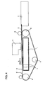
- a belt drive device of this type includes a drive roller a, a subordinate roller b and a tension roller c, with an endless belt d engaged therearound.
- Drive roller a connected to a drive shaft of a motor (not shown), receives the motor's driving force and thus rotates.
- belt d in the figure runs in a direction A.
- a pinch roller e is arranged to cooperate with subordinate roller b to pinch belt d.
- a sheet feed cassette f is arranged, from which a recording medium (a sheet of paper) g is drawn and transported in direction A, pinched together with belt d between subordinate roller b and pinch roller e, as belt d runs.
- a printing head h is arranged above belt d between drive roller a and subordinate roller b.
- the portion of belt d between drive roller a and subordinate roller b will be referred to as a span s.
- Printing head h is a linear head or a serial head.
- the linear head has a multitude of jet nozzles depending on the resolution of interest that are arranged across a printing width as required in a direction perpendicular to the plane of Fig. 4, e.g., 200 mm for a sheet of the A4 size.
- the serial head has several tens to hundreds of jet nozzles in direction A as shown in Fig. 4 and prints an image on recording medium g as it moves in a direction perpendicular to the plane of Fig. 4.
- recording medium g is drawn from sheet feed cassette f, pinched together with belt d between subordinate roller b and pinch roller e and thus transferred in direction A.
- recording medium g is continuously transferred, while the printing head's nozzles jet ink appropriately to print an image on recording medium g.
- recording medium g is initially transferred to the position at which printing head h is arranged.
- belt d halts.
- printing head h jets ink through its nozzles as it moves in the direction perpendicular to the plane of Fig. 4, and it thus prints an image.
- belt d again starts to run and then stops after recording medium g has been moved by a predetermined distance.
- printing head h then again moves in the direction perpendicular to the plane of Fig. 4 and thus prints an image.
- the print operation by printing head h and the recording-medium transport operation by the belt drive device are alternately provided to print an image on recording medium g.
- One exemplary device of this type also includes a platen chamber i arranged on a back side of the belt's span s existing between drive roller a and subordinate roller b.
- Platen chamber i can aspirate recording medium g on belt d so that recording medium g does not displace and is thus transported satisfactorily.
- platen chamber i has an upper surface provided with multiple aspiration holes j.
- belt d is also provided with multiple aspiration holes (not shown).
- belt d aspirates recording medium g to prevent any positional displacement of recording medium g while transporting recording medium g.
- the conventional belt drive device configured as above, however, tends to transport recording medium g by a distance larger than a predetermined distance. If such event occurs, a difference would be introduced between the driveability of belt d and the transportability of recording medium g. Thus, recording medium g would slide relative to belt d and thus be positionally displaced from a predetermined position. As a result, recording medium g would be transported with less precision or worse it would come off belt d and contact printing head h or divert from a transporting path and jam up the machine of interest, resulting in an unsatisfactory print operation. As such, recording-medium transport devices using such conventional belt drive device are still disadvantageous in transporting recording medium g.
- the present inventors have studied what introduces a difference between the driveability of belt d and the transportability of recording medium g and have found that such difference is introduced by the following event:
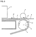
- belt d when recording medium g is introduced between subordinate roller b and pinch roller e, in a vicinity of the portion pinched by rollers b and e, which will be referred to as a nip hereinafter, belt d has a front surface running at an temporarily increased rate, which introduces the difference between the driveability of belt d and the transportability of recording medium g. More specifically, belt d around subordinate roller b has an expanding front surface and a contracting back surface. Furthermore, as indicated in Fig. 5 by a broken line, belt d has a layer approximately intermediate as seen in a direction of the belt's thickness that neither expands nor contracts.
- V n r n ⁇ ⁇
- the belt's front surface runs faster than the belt's intermediate layer by the difference between the two rates, i.e., ⁇ r ⁇ ⁇ .
- a front surface of belt d not around subordinate roller b e.g., that of belt d opposite to printing head h, no longer expands and thus runs at a reduced rate and thus the same rate as the belt's intermediate layer.
- belt d has a front surface running faster at subordinate roller b (at a rate V1 in Fig. 5) than at printing head h (at a rate V2 in Fig. 5). Because of such difference in rate, in Fig. 5 at the nip there would work a force which would transport recording medium g on a front surface of belt d at a rate greater than that of the intermediate layer of belt d. That is, recording medium g is transported farther at the nip than at printing head h. As such, recording medium g cannot contact the front surface of belt d, with a result that recording medium g and belt d slide relative to each other or recording medium g comes off the front surface of belt d. Consequently, recording medium g would be brought into contact with printing head h or divert from a transporting path and jam up the machine of interest.
- One object of the present invention is to achieve an image formation, wherein a variation in driveability between a portion of a belt engaging and contacting a roller and a portion of the belt out of contact with the roller does not have any effect on a recording medium being transported, to reliably transport the recording medium to form on the recording medium an image of high quality as well as prevent the recording medium from diverting from a transporting path and thus achieve reliable image formation.
- the endless transport belt has a transporting side bearing thereon and thus transporting a recording medium pinched together with the endless transport belt by the pair of pinch rollers.
- the pair of pinch rollers pinch a portion of the belt out of contact with the plurality of rollers.
- the pair of pinch rollers pinch a portion of the endless transport belt which does not have a curve.
- the belt does not have an expanding surface and in a vicinity of the pair of pinch rollers the belt has a surface running at a constant rate while transporting the recording medium, on which an image formation means forms an image.
- the recording medium can be transported satisfactorily, with high precision.
- the recording medium does not come off the belt or contact a printing head or the like or divert from a transporting path or thus jam up the machine of interest.
- the plurality of rollers with the endless transport belt therearound correspond to a drive roller and a subordinate roller and rotating and thus driving the drive roller allows the endless transport belt to run so that the endless transport belt has an upper surface transporting the recording medium
- the pair of pinch rollers includes an outer pinch roller in contact with the upper surface of the endless transport belt and an inner pinch roller in contact with a back surface of the endless transport belt, wherein the drive roller, the subordinate roller and the inner pinch roller are arranged to have their respective upper edges aligned in a single plane.
- the endless transport belt has an upper surface adapted to transport a recording medium, while on a back side of the recording-medium transporting span of the belt there is provided aspiration means producing a force to aspirate the recording medium on the endless transport belt
- the pair of pinch rollers includes an outer pinch roller in contact with the upper surface of the endless transport belt and an inner pinch roller in contact with an back surface of the endless transport belt and are arranged between a roller with the belt engaged therearound and the aspiration means and wherein the drive roller, the subordinate roller, the aspiration means and the inner pinch roller have their respective upper edges aligned in a single plane.
- the aspiration means is also provided, its aspiration allows the recording medium to be aspirated on the endless transport belt to reliably prevent the recording medium from sliding relative to the belt and having a positional displacement from a predetermined position, thus more reliably transporting the recording medium.
- the recording-medium transport device preferably has the pair of pinch rollers generally equal in outer diameter to allow the endless transport belt to have a front surface and a back surface contacting the paired pinch rollers in the same condition. This ensures that the endless transport belt pinched by the pair of pinch rollers is flat.
- the recording-medium transport device includes registration means starting to run the endless transport belt with a recording medium having its preceding edge abutting between the endless transport belt and an outer pinch roller of the pair of pinch rollers in contact with an upper surface of the endless transport belt, to register the recording medium so that a side of the recording medium that corresponds to the recording medium's preceding edge extends orthogonal to a direction in which the endless transport belt runs, for transporting the recording medium.
- the pair of pinch rollers and the endless transport belt in contact with each other, form therebetween a line (parallel to each pinch roller's rotation axis) parallel to the preceding edge of the recording medium.
- the recording medium with its preceding edge satisfactorily registered in position passes through the pair of pinch rollers.
- Running the endless transport belt with the recording medium thus registered allows the recording medium to be transferred, registered on the endless transport belt, with a longitudinal direction of the preceding edge of the recording medium orthogonal to a direction in which the endless transport belt runs.
- the recording-medium transport device is incorporated into a recording-medium transport system of an image recording apparatus to transport a recording medium on the recording-medium transporting span of the belt and pass the recording medium through the pair of pinch rollers before the image formation means form an image on the recording medium.
- a specific application of the recording-medium transport device of the present invention allowing the image recording apparatus to form an image of high quality.
- Fig. 1 schematically shows a printer of the present embodiment, with a transport system transporting a sheet of paper P as a recording medium and a print system printing an image on the sheet of paper P transported.
- the sheet of paper P is transported by a transport device corresponding to a belt drive device 1 including a drive roller 11, a subordinate roller 12 and a tension roller 13 with an endless belt 14 engaged therearound.
- belt 14 in the figure runs in a direction A.
- the motor is for example a stepping motor driving the roller intermittently for each predetermined step angle. Linked to the motor's driving ability, belt 14 also runs intermittently.
- Above drive roller 11 is arranged a pinch roller 15 cooperating with drive roller 11 to pinch belt 14.
- a printing head 2 as image formation means is arranged above a span S of belt 14 that exists between drive roller 11 and subordinate roller 12.
- Printing head 2 is a serial head having several tens to hundreds of jet nozzles in direction A as shown in Fig. 1 (a direction in which the sheet of paper P is transported).
- Printing head 2 also has means (not shown) for moving the head in a direction perpendicular to the plane of Fig. 1.
- Printing head 2 is provided with cartridges for yellow, magenta, cyan and black colors, allowing full-color printing.
- a pair of pinch rollers 31 and 32 is provided at the belt's span S in a vicinity of subordinate roller 12 to pinch belt 14 at its front surface or transporting side and back surface.
- the pinch-roller pair is formed of an outer pinch roller 31 positioned on a front surface of belt 14 and an inner pinch roller 32 positioned on a back surface of belt 14.
- Inner pinch roller 32 is smaller in diameter than drive roller 11 and subordinate roller 12.
- Outer pinch roller 31 is smaller in diameter than inner pinch roller 32. More specifically, drive roller 11 and subordinate roller 12 has an outer diameter of 25 mm, inner pinch roller 32 has an outer diameter of 20 mm, and outer pinch roller 31 has an outer diameter of 10 mm.
- the pair of pinch rollers 31 and 32 is arranged to maintain the belt's span S flat. More specifically, inner pinch roller 32 has an upper edge positioned on a straight line linking an upper edge of drive roller 11 and that of subordinate roller 12, and outer pinch roller 31 has a lower edge spaced from the upper edge of inner pinch roller 32 by a distance corresponding approximately to the belt's thickness.
- a sheet feeding cassette 4 housing multiple sheets of paper P.
- belt drive device 1 As belt drive device 1 is driven, a sheet of paper P is drawn from sheet feeding cassette 4 and thus transported on belt 4.
- a platen chamber 5 is arranged as aspiration means on a back side of the belt's span S. Platen chamber 5 is spaced from subordinate roller 12 for example by 40 mm. Platen chamber 5 corresponds to a container in the form of a generally rectangular parallelepiped having an upper surface positioned to generally match the straight line linking the upper edge of drive roller 11 and that of subordinate roller 12. Furthermore, platen chamber 5 has an upper surface provided with a plurality of aspiration holes 51 and also has a fan (not shown) driven to create a negative pressure inside the container to produce a force for aspirating the sheet of paper P on belt 14. Thus, the sheet of paper P can be free of displacement relative to belt 14 and thus transported satisfactorily.
- belt 14 also has a plurality of aspiration holes 14a to cause a force aspirating the sheet of paper P on a surface of belt 14 when platen chamber 5 is driven.
- Belt 14 is formed of rubber such as urethane rubber, providing a large friction between the belt's surface and the sheet of paper P.
- belt 14 is for example 0.5 mm thick, with aspiration holes 14a provided in the directions of the length and width of belt 14, spaced for example by an equidistance, or at a pitch, of 20 mm. It should be noted that aspiration holes 14a may have a size and pitch set as desired.
- aspiration holes 14a may have a pitch in the direction of the length of belt 14 and a different pitch in the direction of the width of belt 14, rather than the same pitch in the two directions of belt 14. Aspiration holes 14a may stagger in arrangement. Furthermore, the platen chamber's aspiration force, the sheet's size, thickness, mechanical property and its surface condition such as whether it is a normal paper, a coated paper or any other type of paper, the rate at which the sheet is transported, and the like may also be set as desired.
- the printer configured as above operates as described below:
- drive roller 11 rotates as the motor is driven.
- belt 14 runs in direction A, as shown in Fig. 1.
- a sheet of paper P is drawn from sheet feeding cassette 4.
- the sheet of paper P passes on an upper side of subordinate roller 12 and then arrives at the pair of pinch rollers 31 and 32.
- the sheet of paper P, pinched together with belt 14 by the pair of pinch rollers 31 and 32, is transported toward the position at which printing head 2 is arranged, while belt 14 around subordinate roller 12 has a front surface expanding and thus running at a local, increased rate.
- the pair of pinch rollers 31 and 32 is provided at a position where the belt no longer has an expanding surface or the belt is not wound around subordinate roller 12, pinching the sheet of paper P together with belt 14.
- the sheet of paper P is pinched and it is thus transported toward printing head 2.
- the entirety of the sheet of paper P is transported in a stable manner.
- platen chamber 5 provides a force aspirating the sheet of paper P on belt 14.
- the sheet of paper P can be free of displacement relative to belt 14 and thus transported satisfactorily.
- the pair of pinch rollers 31 and 32 functions to register the sheet of paper P, maintaining it on belt 14 in a satisfactory registration. More specifically, the sheet of paper P on belt 14 is registered such that a longitudinal direction of its preceding edge (in Fig. 1, a direction perpendicular to the plane of the figure) is orthogonal to a direction in which belt 14 runs (direction A in the figure).
- the sheet of paper P can be registered, as described below:
- the sheet of paper P can be registered by slightly curving the sheet of paper P drawn from sheet feeding cassette 4 and feeding the curved sheet of paper P to the pair of pinch rollers 31 and 32. More specifically, before drive roller 11 is driven or while the pair of pinch rollers 31 and 32 and belt 14 stop, a sheet feeding roller (not shown) is driven to draw the sheet of paper P from sheet feeding cassette 4. Then, with its preceding edge positioned between outer pinch roller 31 and belt 14, the sheet of paper P is curved slightly, as represented in Fig. 1 by a virtual line. In this condition, the sheet's recoverability pushes the sheet's preceding edge between outer pinch roller 31 and belt 14.
- outer pinch roller 31 has a line tangential to belt 14 (parallel to the revolution axis of outer pinch roller 31) that is parallel to the sheet's preceding edge.
- the sheet of paper P is transported to the pair of pinch rollers 31 and 32 with its preceding edge positioned, as corrected satisfactorily.
- driving drive roller 11 allows the sheet of paper P to be transported, registered on belt 14, with the longitudinal direction of the sheet's preceding edge orthogonal to the direction in which belt 14 runs.
- the present printer includes a controller (not shown) having registration means to register the sheet of paper P, as described above.
- the registration means controls the drawing of the sheet of paper P and the timing at which the motor is driven, to register the sheet of paper P, as described above.
- belt 14 has span S between drive roller 11 and subordinate roller 12 and the pair of pinch rollers 31 and 32 is provided at span S in a vicinity of subordinate roller 12 to maintain span S flat as it pinches and thus transports the sheet of paper P.
- the belt 14 does not curve and thus transports the sheet of paper P as it is maintained flat.
- the belt has a flat surface running at a constant rate from the nip to the portion opposite to printing head 2.
- the present invention has been described in conjunction with an serial-head equipped ink-jet printer with the present invention applied.
- the present invention is also applicable for example to linear-head equipped printers and electro-photography printers.
- the present invention is also applicable to image recording apparatus other than printers, such as copiers.
- the present invention may use recording media other than the sheet of paper P, such as various types of media including film.
- the present embodiment includes outer pinch roller 31 smaller in diameter than inner pinch roller 32
- the present invention may alternatively have pinch rollers 31 and 32 equal in outer diameter.
- belt 14 can have a front surface and a back surface contacting pinch rollers 31 and 32 in the same condition. This ensures that belt 14 is flat at the nip. Thus there can be readily obtained a configuration allowing the above embodiment to operate effectively.
- pinch rollers 31 and 32 may be each precisely adjusted in level. Such means can precisely adjust pinch rollers 31 and 32 in level to allow belt 14 to have a front surface maintained flat if belt drive device 1 includes a component having a processing error or the like. Furthermore, if each of pinch rollers 31 and 32 can be precisely adjusted in level to allow belt 14 to voluntarily engage itself around pinch rollers 31 and 32, the sheet of paper P would for example be introduced at a any rate variable as desired. It should be noted, however, that the rollers be precisely adjusted so that the sheet of paper P does not slide on belt 14.
- belt 14 may have a surface formed of rubber such as urethane rubber and an internal portion reinforced with a core formed of a cloth woven with polyester fabric.
- belt 14 can transport a recording medium with high precision, with a high rigidity in a direction of tension.
Landscapes
- Engineering & Computer Science (AREA)
- Mechanical Engineering (AREA)
- Delivering By Means Of Belts And Rollers (AREA)
- Ink Jet (AREA)
- Handling Of Sheets (AREA)
Claims (5)
- Transportvorrichtung für einen Aufzeichnungsträger, mit mehreren Walzen (11, 12, 13), mit denen ein um sie geführtes Endlos-Transportband (14) in Eingriff steht;- wobei das Endlos-Transportband (14) über einen Abschnitt verfügt, der einer Spanne (S) zum Transportieren eines Aufzeichnungsträgers (P) entspricht, und mit einer Transportseite, die einen Aufzeichnungsträger (P) trägt;- wobei diese Transportvorrichtung für einen Aufzeichnungsträger ferner über ein Paar von Klemmwalzen (31, 32) verfügt, die mit der Transportseite der Spanne (S) bzw. der Rückseite derselben in Kontakt stehen, während die Spanne (S) flach gehalten wird, um den Aufzeichnungsträger (P) gemeinsam mit dem Endlos-Transportband (14) zu klemmen;
wobei- eine Bilderzeugungseinrichtung (2) ein Bild auf dem Aufzeichnungsträger (P) erzeugt;- der Transport des Aufzeichnungsträgers (P) zur Bilderzeugungseinrichtung (2) durch den Klemmvorgang erfolgt; und- diese Transportvorrichtung für einen Aufzeichnungsträger über eine Ausrichteinrichtung verfügt, die es ermöglicht, dass der Lauf des Endlos-Transportbands (14) startet, wenn die Vorderkante des Aufzeichnungsträgers (P) zwischen dem Endlos-Transportband (14) und einer äußeren Klemmwalze (31) des Paars von Klemmwalzen (31, 32) in Kontakt mit der Oberseite des Endlos-Transportbands (14) anstößt, um den Aufzeichnungsträger (P) so auszurichten, dass sich seine Seite, die seiner Vorderkante entspricht orthogonal zur Richtung erstreckt, in der das Endlos-Transportband (14) läuft, um den Aufzeichnungsträger (P) zu transportieren. - Transportvorrichtung für einen Aufzeichnungsträger nach Anspruch 1, bei der die mehreren Walzen (11, 12, 13) einer Antriebswalze (11) und einer Hilfswalze (12) entsprechen, wobei die Antriebswalze (11) gedreht wird und so angetrieben wird, damit das Endlos-Transportband (14) laufen kann und so über eine den Aufzeichnungsträger (P) transportierende Oberseite verfügt, während das Paar von Klemmwalzen (31, 32) über eine äußere Klemmwalze (31) in Kontakt mit der Oberseite des Endlos-Transportbands (14) und eine innere Klemmwalze (32) in Kontakt mit der Rückseite desselben verfügt, wobei die Antriebswalze (11), die Hilfswalze (12), und die innere Klemmwalze (32) so angeordnet sind, dass ihre jeweiligen Oberkanten in einer einzelnen Ebene ausgerichtet sind.
- Transportvorrichtung für einen Aufzeichnungsträger nach Anspruch 1, bei der das Endlos-Transportband (14) über eine Oberseite verfügt, die so ausgebildet ist, dass sie den Aufzeichnungsträger (P) transportiert, während an der Rückseite der Spanne (S) eine Saugeinrichtung (5) vorhanden ist, die eine Kraft zum Ansaugen des Aufzeichnungsträgers (P) auf das Endlos-Transportband (14) erzeugt, wobei das Paar von Klemmwalzen (31, 32) über eine äußere Klemmwalze (31) in Kontakt mit der Oberseite des Endlos-Transportbands (14) und eine innere Klemmwalze (32) in Kontakt mit der Rückseite desselben verfügt, und mit Anordnung zwischen der Hilfswalze (12) und der Saugeinrichtung (5), wobei die jeweiligen Oberkanten der Antriebswalze (11), der Saugeinrichtung (5) und der inneren Klemmwalze (32) in einer einzelnen Ebene ausgerichtet sind.
- Transportvorrichtung für einen Aufzeichnungsträger nach Anspruch 1, bei der das Paar von Klemmwalzen (32) im Wesentlichen denselben Außendurchmesser aufweist.
- Transportvorrichtung für einen Aufzeichnungsträger nach Anspruch 1, die in ein Aufzeichnungsträger-Transportsystem einer Bildaufzeichnungsvorrichtung eingebaut ist, um den Aufzeichnungsträger (P) auf der Spanne (S) zu transportieren und ihn durch das Paar von Klemmwalzen (32) zu führen, bevor die Bilderzeugungseinrichtung (2) ein Bild auf ihm erzeugt.
Applications Claiming Priority (2)
| Application Number | Priority Date | Filing Date | Title |
|---|---|---|---|
| JP16547699 | 1999-06-11 | ||
| JP11165476A JP2000351477A (ja) | 1999-06-11 | 1999-06-11 | 記録媒体搬送装置 |
Publications (3)
| Publication Number | Publication Date |
|---|---|
| EP1060897A2 EP1060897A2 (de) | 2000-12-20 |
| EP1060897A3 EP1060897A3 (de) | 2002-03-06 |
| EP1060897B1 true EP1060897B1 (de) | 2006-05-31 |
Family
ID=15813139
Family Applications (1)
| Application Number | Title | Priority Date | Filing Date |
|---|---|---|---|
| EP00112301A Expired - Lifetime EP1060897B1 (de) | 1999-06-11 | 2000-06-08 | Transportvorrichtung eines Aufzeichnungsträgers |
Country Status (4)
| Country | Link |
|---|---|
| US (1) | US6575459B1 (de) |
| EP (1) | EP1060897B1 (de) |
| JP (1) | JP2000351477A (de) |
| DE (1) | DE60028293T2 (de) |
Families Citing this family (13)
| Publication number | Priority date | Publication date | Assignee | Title |
|---|---|---|---|---|
| DE10162444B4 (de) | 2001-02-06 | 2008-06-26 | Heidelberger Druckmaschinen Ag | Vorrichtung zum gleichzeitigen Ansaugen und Transportieren eines Bogens |
| DE10122716A1 (de) * | 2001-05-10 | 2002-11-14 | Baeuerle Gmbh Mathias | Transporteinrichtung für flaches Transportgut, vorzugsweise Papier |
| AT501863B1 (de) * | 2005-05-25 | 2007-08-15 | Durst Phototech Digital Tech | Haltevorrichtung für tintenstrahldrucker |
| JP2008080526A (ja) * | 2006-09-26 | 2008-04-10 | Brother Ind Ltd | 液体噴射装置 |
| JP4921280B2 (ja) | 2007-08-10 | 2012-04-25 | 株式会社リコー | 画像形成装置 |
| JP5276955B2 (ja) * | 2008-11-10 | 2013-08-28 | 理想科学工業株式会社 | 印刷装置の搬送機構 |
| US7837195B2 (en) * | 2009-01-29 | 2010-11-23 | Xerox Corporation | Angled pressure roll used with vacuum belts |
| US7988150B2 (en) * | 2009-02-24 | 2011-08-02 | Xerox Corporation | Media transport device with vacuum-controlled positioning |
| JP2013212917A (ja) * | 2012-04-03 | 2013-10-17 | Konica Minolta Inc | 用紙搬送装置及び画像形成装置 |
| DE102012206847A1 (de) | 2012-04-25 | 2013-11-07 | E.C.H. Will Gmbh | Saugfördervorrichtung zum Transport von Flachteilen |
| JP6204274B2 (ja) * | 2014-06-11 | 2017-09-27 | 京セラドキュメントソリューションズ株式会社 | 搬送装置及びインクジェット記録装置 |
| JP6703300B2 (ja) * | 2016-02-19 | 2020-06-03 | セイコーエプソン株式会社 | 記録装置 |
| KR102325571B1 (ko) * | 2021-07-13 | 2021-11-15 | 주식회사 딜리 | 연속출력이 가능한 하이브리드 잉크젯 프린터 |
Family Cites Families (4)
| Publication number | Priority date | Publication date | Assignee | Title |
|---|---|---|---|---|
| US5197812A (en) * | 1989-11-09 | 1993-03-30 | Dataproducts Corporation | High accuracy vacuum belt and pinch roller media transport mechanism |
| JPH06135613A (ja) | 1992-10-22 | 1994-05-17 | Fuji Xerox Co Ltd | 複写機における用紙搬送装置 |
| AUPN596195A0 (en) * | 1995-10-12 | 1995-11-09 | Intelmail Australia Pty. Ltd. | Paper handling apparatus |
| US5740728A (en) * | 1996-09-23 | 1998-04-21 | Pitney Bowes Inc. | Mailing machine |
-
1999
- 1999-06-11 JP JP11165476A patent/JP2000351477A/ja active Pending
-
2000
- 2000-06-08 EP EP00112301A patent/EP1060897B1/de not_active Expired - Lifetime
- 2000-06-08 DE DE60028293T patent/DE60028293T2/de not_active Expired - Lifetime
- 2000-06-09 US US09/590,971 patent/US6575459B1/en not_active Expired - Lifetime
Also Published As
| Publication number | Publication date |
|---|---|
| DE60028293D1 (de) | 2006-07-06 |
| JP2000351477A (ja) | 2000-12-19 |
| EP1060897A3 (de) | 2002-03-06 |
| DE60028293T2 (de) | 2007-06-06 |
| US6575459B1 (en) | 2003-06-10 |
| EP1060897A2 (de) | 2000-12-20 |
Similar Documents
| Publication | Publication Date | Title |
|---|---|---|
| JP3469824B2 (ja) | 記録媒体搬送装置 | |
| EP1060897B1 (de) | Transportvorrichtung eines Aufzeichnungsträgers | |
| KR100810181B1 (ko) | 시트 반송 장치 | |
| US4532525A (en) | Image forming device | |
| EP0673776B1 (de) | Drucker für die Endlospapierzuführung zum Druckbereich | |
| JP3434252B2 (ja) | 記録媒体搬送装置 | |
| US7577396B2 (en) | Printing apparatus | |
| US6817609B2 (en) | Printer sheet lateral registration system with automatic upstream nip disengagements for different sheet size | |
| JPH0853252A (ja) | ディスクタイプシートスタック装置及びディスクタイプシートスタック装置を含む静電写真印刷機 | |
| EP1022147B1 (de) | Medientransportsystem | |
| US6341908B1 (en) | Method and apparatus for controlling print media shape during media transport | |
| JP3935310B2 (ja) | プリンタの媒体形状制御用内部紙案内 | |
| EP1108555B1 (de) | Aufzeichnungsgerät | |
| JP2001002284A (ja) | 記録媒体搬送装置 | |
| EP1043167B1 (de) | Aufzeichnungsgerät | |
| JP2000246982A (ja) | インクジェット記録装置及び用紙搬送装置 | |
| US6851879B2 (en) | Image-recording device | |
| US6499733B1 (en) | Method and apparatus for feeding sheet material into a printer or copier | |
| JP2024018272A (ja) | 媒体搬送装置および画像形成装置 | |
| JPH08295438A (ja) | 画像形成装置 | |
| JPH11216919A (ja) | 画像記録装置、及び同画像記録装置における記録媒体搬送方法 | |
| JPS63158274A (ja) | カラ−ラインプリンタ | |
| JP2003094745A (ja) | インクジェット記録装置 | |
| JPH0930041A (ja) | 画像形成装置 | |
| JP2006026959A (ja) | 画像形成タイミング補正システム及びその補正方法 |
Legal Events
| Date | Code | Title | Description |
|---|---|---|---|
| PUAI | Public reference made under article 153(3) epc to a published international application that has entered the european phase |
Free format text: ORIGINAL CODE: 0009012 |
|
| AK | Designated contracting states |
Kind code of ref document: A2 Designated state(s): AT BE CH CY DE DK ES FI FR GB GR IE IT LI LU MC NL PT SE Kind code of ref document: A2 Designated state(s): DE FR GB |
|
| AX | Request for extension of the european patent |
Free format text: AL;LT;LV;MK;RO;SI |
|
| PUAL | Search report despatched |
Free format text: ORIGINAL CODE: 0009013 |
|
| AK | Designated contracting states |
Kind code of ref document: A3 Designated state(s): AT BE CH CY DE DK ES FI FR GB GR IE IT LI LU MC NL PT SE |
|
| AX | Request for extension of the european patent |
Free format text: AL;LT;LV;MK;RO;SI |
|
| RIC1 | Information provided on ipc code assigned before grant |
Free format text: 7B 41J 13/08 A, 7B 65H 5/02 B, 7G 03G 15/00 B, 7B 65H 5/22 B |
|
| AKX | Designation fees paid | ||
| 17P | Request for examination filed |
Effective date: 20020620 |
|
| RBV | Designated contracting states (corrected) |
Designated state(s): DE FR GB |
|
| REG | Reference to a national code |
Ref country code: DE Ref legal event code: 8566 |
|
| GRAP | Despatch of communication of intention to grant a patent |
Free format text: ORIGINAL CODE: EPIDOSNIGR1 |
|
| GRAS | Grant fee paid |
Free format text: ORIGINAL CODE: EPIDOSNIGR3 |
|
| GRAA | (expected) grant |
Free format text: ORIGINAL CODE: 0009210 |
|
| AK | Designated contracting states |
Kind code of ref document: B1 Designated state(s): DE FR GB |
|
| REG | Reference to a national code |
Ref country code: GB Ref legal event code: FG4D |
|
| REF | Corresponds to: |
Ref document number: 60028293 Country of ref document: DE Date of ref document: 20060706 Kind code of ref document: P |
|
| ET | Fr: translation filed | ||
| PLBE | No opposition filed within time limit |
Free format text: ORIGINAL CODE: 0009261 |
|
| STAA | Information on the status of an ep patent application or granted ep patent |
Free format text: STATUS: NO OPPOSITION FILED WITHIN TIME LIMIT |
|
| 26N | No opposition filed |
Effective date: 20070301 |
|
| PGFP | Annual fee paid to national office [announced via postgrant information from national office to epo] |
Ref country code: GB Payment date: 20140604 Year of fee payment: 15 |
|
| PGFP | Annual fee paid to national office [announced via postgrant information from national office to epo] |
Ref country code: DE Payment date: 20140603 Year of fee payment: 15 |
|
| PGFP | Annual fee paid to national office [announced via postgrant information from national office to epo] |
Ref country code: FR Payment date: 20140609 Year of fee payment: 15 |
|
| REG | Reference to a national code |
Ref country code: DE Ref legal event code: R119 Ref document number: 60028293 Country of ref document: DE |
|
| GBPC | Gb: european patent ceased through non-payment of renewal fee |
Effective date: 20150608 |
|
| REG | Reference to a national code |
Ref country code: FR Ref legal event code: ST Effective date: 20160229 |
|
| PG25 | Lapsed in a contracting state [announced via postgrant information from national office to epo] |
Ref country code: DE Free format text: LAPSE BECAUSE OF NON-PAYMENT OF DUE FEES Effective date: 20160101 Ref country code: GB Free format text: LAPSE BECAUSE OF NON-PAYMENT OF DUE FEES Effective date: 20150608 |
|
| PG25 | Lapsed in a contracting state [announced via postgrant information from national office to epo] |
Ref country code: FR Free format text: LAPSE BECAUSE OF NON-PAYMENT OF DUE FEES Effective date: 20150630 |