EP1060112B1 - Ausrichtförderer mit seitlich verstellbarer umlenkrolle am ende - Google Patents
Ausrichtförderer mit seitlich verstellbarer umlenkrolle am ende Download PDFInfo
- Publication number
- EP1060112B1 EP1060112B1 EP98910027A EP98910027A EP1060112B1 EP 1060112 B1 EP1060112 B1 EP 1060112B1 EP 98910027 A EP98910027 A EP 98910027A EP 98910027 A EP98910027 A EP 98910027A EP 1060112 B1 EP1060112 B1 EP 1060112B1
- Authority
- EP
- European Patent Office
- Prior art keywords
- belt
- exit end
- conveyor
- transverse housing
- strip component
- Prior art date
- Legal status (The legal status is an assumption and is not a legal conclusion. Google has not performed a legal analysis and makes no representation as to the accuracy of the status listed.)
- Expired - Lifetime
Links
Images


Classifications
-
- B—PERFORMING OPERATIONS; TRANSPORTING
- B29—WORKING OF PLASTICS; WORKING OF SUBSTANCES IN A PLASTIC STATE IN GENERAL
- B29D—PRODUCING PARTICULAR ARTICLES FROM PLASTICS OR FROM SUBSTANCES IN A PLASTIC STATE
- B29D30/00—Producing pneumatic or solid tyres or parts thereof
- B29D30/06—Pneumatic tyres or parts thereof (e.g. produced by casting, moulding, compression moulding, injection moulding, centrifugal casting)
- B29D30/08—Building tyres
- B29D30/20—Building tyres by the flat-tyre method, i.e. building on cylindrical drums
- B29D30/30—Applying the layers; Guiding or stretching the layers during application
- B29D30/3007—Applying the layers; Guiding or stretching the layers during application by feeding a sheet perpendicular to the drum axis and joining the ends to form an annular element
-
- B—PERFORMING OPERATIONS; TRANSPORTING
- B65—CONVEYING; PACKING; STORING; HANDLING THIN OR FILAMENTARY MATERIAL
- B65G—TRANSPORT OR STORAGE DEVICES, e.g. CONVEYORS FOR LOADING OR TIPPING, SHOP CONVEYOR SYSTEMS OR PNEUMATIC TUBE CONVEYORS
- B65G39/00—Rollers, e.g. drive rollers, or arrangements thereof incorporated in roller-ways or other types of mechanical conveyors
- B65G39/02—Adaptations of individual rollers and supports therefor
- B65G39/07—Other adaptations of sleeves
- B65G39/071—Other adaptations of sleeves for aligning belts or sheets
-
- B—PERFORMING OPERATIONS; TRANSPORTING
- B65—CONVEYING; PACKING; STORING; HANDLING THIN OR FILAMENTARY MATERIAL
- B65H—HANDLING THIN OR FILAMENTARY MATERIAL, e.g. SHEETS, WEBS, CABLES
- B65H23/00—Registering, tensioning, smoothing or guiding webs
- B65H23/02—Registering, tensioning, smoothing or guiding webs transversely
- B65H23/032—Controlling transverse register of web
-
- B—PERFORMING OPERATIONS; TRANSPORTING
- B29—WORKING OF PLASTICS; WORKING OF SUBSTANCES IN A PLASTIC STATE IN GENERAL
- B29L—INDEXING SCHEME ASSOCIATED WITH SUBCLASS B29C, RELATING TO PARTICULAR ARTICLES
- B29L2030/00—Pneumatic or solid tyres or parts thereof
- B29L2030/002—Treads
-
- B—PERFORMING OPERATIONS; TRANSPORTING
- B65—CONVEYING; PACKING; STORING; HANDLING THIN OR FILAMENTARY MATERIAL
- B65H—HANDLING THIN OR FILAMENTARY MATERIAL, e.g. SHEETS, WEBS, CABLES
- B65H2511/00—Dimensions; Position; Numbers; Identification; Occurrences
- B65H2511/20—Location in space
-
- B—PERFORMING OPERATIONS; TRANSPORTING
- B65—CONVEYING; PACKING; STORING; HANDLING THIN OR FILAMENTARY MATERIAL
- B65H—HANDLING THIN OR FILAMENTARY MATERIAL, e.g. SHEETS, WEBS, CABLES
- B65H2701/00—Handled material; Storage means
- B65H2701/10—Handled articles or webs
- B65H2701/12—Surface aspects
- B65H2701/124—Patterns, marks, printed information
- B65H2701/1241—Patterns, marks, printed information register marks
- B65H2701/12411—Patterns, marks, printed information register marks line
-
- B—PERFORMING OPERATIONS; TRANSPORTING
- B65—CONVEYING; PACKING; STORING; HANDLING THIN OR FILAMENTARY MATERIAL
- B65H—HANDLING THIN OR FILAMENTARY MATERIAL, e.g. SHEETS, WEBS, CABLES
- B65H2801/00—Application field
- B65H2801/93—Tyres
Definitions
- This invention pertains to the art of methods and apparatuses for conveying materials, such as strip components on a belt conveyor, and more specifically to methods and apparatuses for conveying tire building components from a feeding extruder or other production location to a tire building drum on a belt conveyor which is capable of laterally adjusting the position of the components without using guides.
- International Application WO 98/0448 is directed to steering and guiding a strip component after conveying the strip component to an exit end with a plurality of guide disks canted at an angle to the shaft axis and by transverse movement of the disks.
- Another guiding method utilized curved modular belt conveyors however, the curves were static and did not act as active guides. Further, the belting typically used was more than twice the pitch leagth of that utilized by the present invention. Long pitch lengths introduce excessive speed undulation to the product due to chordal action at the sprockets.
- the present invention contemplates a new and improved flexible guide belt conveyor which is simple in design, effective in use, and overcomes the foregoing difficulties and others while providing better and more advantageous overall results.
- anew and improved flexible guide belt conveyor is provided which allows for active guiding of a fragile strip component on a feeder conveyor without using guides in contact with the material of the strip component,
- a method of conveying an elongated strip component and centering the strip component comprising the step of conveying the component on a first belt of a first belt conveyor having an entrance end and an exit end, method being characterised by the steps of:
- a method of applying tire components to a tire building drum including the step of transferring the tire components on at least one belt conveyor having an entrance end and an exit end, the method characterized by the steps of determining a location of the guideline of the tread member at the exit end of the at least one belt conveyor by means of a sensor, activating a linear actuator to laterally move the transverse housing located at the exit end to adjust the exit end of at least one belt conveyor to align the tread member with a guideline of a tire building drum.
- a belt conveyor having an entrance end and an exit end, with apparatus for adjusting the exit end of a belt conveyor including a laterally adjustable belt characterized by:
- an apparatus for adjusting exit ends of a plurality of belt conveyors each of the belt conveyors comprising a plurality of spaced apart modules supported by hinge pins thereby providing lateral flexibility characterized by each of the belt conveyors having a fixed frame at an entry end and a laterally moveable transverse housing at one of the exit ends, and the fixed frame and the transverse housing having slide plates to support and permit lateral adjustment of the belt conveyors.
- a method of adjusting an exit end of a belt conveyor conveying a strip component characterized by the steps of sensing a position of a guideline of the strip component with sensing means, and activating a linear actuator to move a transverse housing of the conveyor, thereby moving a belt on the conveyor and the strip component until the guideline of the strip component is centered with respect to a predetermined position.
- One advantage of the present invention is its ability to laterally adjust the position of a component transported on a conveyor belt without contacting the edges of the component.
- Another advantage of the present invention is its ability to synchronise the movement of strip components on at least two conveyor belts.
- Another advantage of the present invention is its ability to adjust the positions of tho guidelines of multiple components on multiple conveyor belts.
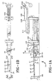
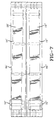
- FIG. 1A shows a side elevation of a conveyor assembly 1.0 for conveying strip materials such as a tire tread 11 to a tire building drum 12.
- the conveyor assembly 10 preferably includes at least one feed belt conveyor 16 having an entrance end 18 and an exit end 20 that is capable of carrying the tire tread 11.
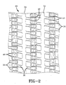
- the feed belt conveyor 16 preferably utilizes a laterally flexible conveyor belt having linked modules 34 with links 36 joined by hinge pins 40, as shown in Figure 2. There is preferably a small amount of clearance between the links 36 of the modules 34, thereby permitting limited lateral shifting and flexibility of the conveyor belt 28. While the conveyor belt 28 described above is the preferred embodiment, any other type of conveyor belt 28 with lateral flexibility may be utilized with the present invention.
- the continuous tire tread 11 is conveyed by the feed conveyor 16 from a feeding position 30 to the exit end 20 and preferably has a guideline rib 52, as shown in Figure 3.
- the guideline rib 52 as shown in Figure 3 is along the centerline of tire tread 11. However, the guideline rib 52 may also be off center.
- the guideline rib 52 may be detected by a die-line sensor 58.
- the sensor 58 determines the relative location of the guideline rib 52 of the tire tread 11 and provides an analog signal that is transmitted to a motion controller assembly 64.
- the motion controller assembly 64 uses the analog signal for negative feedback to a position loop that controls the lateral location of the exit end 20 of the feed belt conveyor 16.
- the sensor 58 consists of a retro-reflective infrared scanner and a DOS based PC-compatible computer and monitor.
- the motion controller 64 moves the exit end 20 of the feed belt conveyor 16 laterally at 90° to the direction of the feed conveyor 16.
- the exit end 20 of the feed belt conveyor 16 includes a lateral adjustable transverse housing 76.
- the entrance end 18 of the feed conveyor 16 is preferably fixed, and is supported by a fixed frame 88.
- the transverse housing 76 preferably has a slider plate 94 to support the conveyor belt 28.
- guides 100 which may be made of plastic or any other suitable material, are preferably provided to ensure that the conveyor belt 28 is not skewed as it enters and leaves sprockets 106.
- Belt idler sprockets 112, and shafting are mounted at the entrance end 18 of the feed conveyor 16, as shown in Figure 1A.
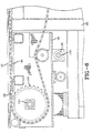
- the transverse housing 76 which encloses the belt drive sprockets 106 and bearings 118 that support most of the weight of the transverse housing is carried on a hollow shaft 124.
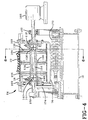
- the remaining weight of the transverse housing 76 is carried by a ball bushing 130 on a shaft 132 mounted on the frame 88, as shown in Figure 6.
- Two ball spline nuts 136, 142 mounted on a drive shaft 144 arc retained inside the hollow shaft 124 of the transverse housing 76.
- One ball spline nut 136 is keyed on its outside diamexer 148 to the inside diameter 154 of the hollow shaft 124 for torque transmission.
- the drive shaft 144 which is supported by pillow blocks 160 and 162, is coupled to a servo motor drive 166.
- Lateral transverse movement of the hollow shaft 124 and transverse housing 76 is provided preferably by a dedicated DC motor-powered linear actuator 172 connected to the housing by arm 174 when activated and controlled by the motion controller 64.
- This assembly at the exit end 20 provides low friction lateral motion of the transverse housing 76.
- the transverse housing 76 is automatically positioned in its center position by the motion controller 64 of the linear actuator 172.
- the strip material 22 is placed on the feed conveyor 16 at a location on the conveyor belt 28 which is not critical.
- the strip material 22 is easily self fed through the guide section.
- the position of the strip material 22 exiting the feed belt conveyor 16 is monitored by the sensor 58. If an off center position of the strip material 22 is detected, the motion controller 64 moves the transverse housing 76 laterally by activating the linear actuator 172.
- the plastic guides 100 which are fixed to the transverse housing 76 force the belt 28 to move with the transverse housing 76.
- the radially extending part of the guides 100 act as fulcrums when the belt 20 shifts sideways.
- the inherent lateral flexibility of the conveyor belt 28 permits this movement while the slider plate 94 supports the belt as described above.
- the strip material 22 is accordingly presented to downstream equipment on center and in line with the guideline of the conveyor assembly 10.
- the present invention has been described with regards to a single belt feed conveyor 16.
- the invention may also be utilized for two or more belt feed conveyors 16',16", as shown in Figure 5.
- Figures 6 and 7 show additional views of the two conveyor assembly as shown in Figure 5.
- the hollow shafts 124',124" are preferably keyed to the drive shaft 144 and coupled together. This allows for the two transverse housings 76',76" to be driven by a single motor.
- Slider plates 94', 95" not shown are similar to slider plate 94 shown in Figure 6 and support the laterally adjustable conveyor belts 28', 28".
- the multiple transverse housings 76',76" arrangement provides continued low friction independent lateral movement of the transverse housings as well as synchronized line speed of the conveyor belts 28',28". If non-synchronized speeds of conveyor belts 28',28" are desired, the splined hollow shafts 124',124" may be uncoupled and driven by separate drives.
- the tread 11 may be applied directly to a tire drum 12.
- the tread 11 is centered by the transverse housing 76 and transferred to a cut conveyor 184 where it is cut by a cut conveyor knife 190.
- the tread 196 has a leading end 202 and a tail end 208, The tread 196 which is still in the centered position is then transferred onto a tread applier 214 and conveyed to the tire building drum 12 where it is applied in the centered position to the drum.
- the method described above is typically used when the strip material 22 is a tread 11 and consists of tread material.
Landscapes
- Engineering & Computer Science (AREA)
- Mechanical Engineering (AREA)
- Tyre Moulding (AREA)
- Framework For Endless Conveyors (AREA)
- Control Of Conveyors (AREA)
Claims (5)
- Verfahren zum Befördern einer länglichen Streifenkomponente (11) und Zentrieren der Streifenkomponente (11), mit dem Schritt des Beförderns der Komponente (11) an einem ersten Band (28) eines ersten Bandförderers (16) mit einem Eintrittsende (18) und einem Austrittsende (20), wobei das Verfahren gekennzeichnet ist durch die Schritte:(a) Bestimmen eines Ortes einer Leitlinie (52) der länglichen Streifenkomponente (11) an dem Austrittsende (20) des ersten Bandförderers (16) mit Benutzen eines Sensors (58);(b) Übertragen des Ortes der Leitlinie (52) auf eine Bewegungssteuerung (64); und(c) Aktivieren eines Linearaktuators (172) zur seitlichen Bewegung eines ein Band abstützenden Quergehäuses (76), das an dem Austrittsende (20) angeordnet ist, um das Austrittsende (20) des ersten Bandes (28) zum Ausrichten der länglichen Streifenkomponente (11) mit einer vorgegebenen Leitlinie an dem Austrittsende (20) einzustellen, und zum Führen des ersten Bandes (28) durch an dem Quergehäuse (76) angebrachte Kantenführungen (100) unter Abstützen des ersten Bandes (28) an einer an dem Quergehäuse (76) angebrachten Gleitplatte (94).
- Verfahren nach Anspruch 1, das weiter einen zweiten Bandförderer (16") zum Fördern einer zweiten länglichen Streifenkomponente (22") an einem zweiten Band (28") und zum Zentrieren der zweiten Streifenkomponente (22") um eine zweite Leitlinie umfasst, weiter gekennzeichnet durch Führen des zweiten Bandes (28") mittels an einem zweiten Quergehäuse (76") angebrachten zweiten Kantenführungen (100) unter Abstützen des zweiten Bandes (28") an einer an dem zweiten Quergehäuse (76") angebrachten zweiten Gleitplatte (94), um eine seitliche Bewegung des die zweite Streifenkomponente (22") tragenden zweiten Bandes (28") an dem Austrittsende (20) zuzulassen und den ersten Bandförderer (16) und den zweiten Bandförderer (16") mit der gleichen Geschwindigkeit durch ein einziges Antriebsmittel (166) anzutreiben.
- Bandförderer mit einem Eintrittsende (18) und einem Austrittsende (20), mit Vorrichtung zum Einstellen des Austrittsendes (20) des Bandförderers (16) einschließlich eines in seitlicher Richtung einstellbaren Bandes (28), dadurch gekennzeichnet, dass:(a) der Bandförderer (16) an dem Eintrittsende (18) eine befestigte Stütze (88), ein in seitlicher Richtung bewegbares Bandstütz-Quergehäuse (76) an dem Austrittsende (20), an dem Quergehäuse (76) angebrachte Antriebsmittel (166), mindestens zwei an dem Quergehäuse (76) angebrachte Kantenführungen (100) zum Führen des Bandes (28) in Querrichtung an dem Austrittsende (20), und eine an dem Gehäuse (76) angebrachte Gleitplatte (94) zum Abstützen und Zulassen einer seitlichen Bewegung des Bandes (28) an dem Austrittsende (20) aufweist.
- Vorrichtung nach Anspruch 3, weiter dadurch gekennzeichnet, dass:(a) das Quergehäuse (76) ein Bandantriebszahnrad (106), Lager (118) und eine genutete Antriebswelle (144) enthält, wobei das Bandantriebszahnrad (106) und die Lager (118) auf einer Hohlwelle (124) getragen sind, wobei die Hohlwelle (124) eine erste Mutter mit Kugelverzahnung (136) und eine zweite Mutter mit Kugelverzahnung (142) zurückhält, die gleitbar an der genuteten Antriebswelle (144) angebracht sind, wobei die erste Mutter mit Kugelverzahnung (136) einen mit einem Innendurchmesser der Hohlwelle (124) zur Drehmomentübertragung über eine Kerbverzahnung verbundenen Außendurchmesser aufweist.
- Vorrichtung nach Anspruch 4, weiter dadurch gekennzeichnet, dass:(a) Mittel zur seitlichen Bewegung des Bandabstütz-Quergehäuses (76) längs der Hohlwelle (144) vorgesehen sind, wobei die Mittel zur seitlichen Bewegung des Quergehäuses (76) einen Linearaktuator (172) umfassen, und(b) das Bandantriebszahnrad (106) des Quergehäuses (76) durch Drehen der Antriebswelle (144) gedreht wird.
Applications Claiming Priority (1)
| Application Number | Priority Date | Filing Date | Title |
|---|---|---|---|
| PCT/US1998/003324 WO1999042390A1 (en) | 1998-02-18 | 1998-02-18 | Guide conveyor having a laterally adjustable deflector roller at the end |
Publications (2)
| Publication Number | Publication Date |
|---|---|
| EP1060112A1 EP1060112A1 (de) | 2000-12-20 |
| EP1060112B1 true EP1060112B1 (de) | 2003-05-21 |
Family
ID=22266428
Family Applications (1)
| Application Number | Title | Priority Date | Filing Date |
|---|---|---|---|
| EP98910027A Expired - Lifetime EP1060112B1 (de) | 1998-02-18 | 1998-02-18 | Ausrichtförderer mit seitlich verstellbarer umlenkrolle am ende |
Country Status (9)
| Country | Link |
|---|---|
| EP (1) | EP1060112B1 (de) |
| JP (1) | JP2002503575A (de) |
| AU (1) | AU6437298A (de) |
| BR (1) | BR9815437A (de) |
| CA (1) | CA2315714A1 (de) |
| DE (1) | DE69814930T2 (de) |
| ES (1) | ES2199428T3 (de) |
| WO (1) | WO1999042390A1 (de) |
| ZA (1) | ZA99943B (de) |
Families Citing this family (6)
| Publication number | Priority date | Publication date | Assignee | Title |
|---|---|---|---|---|
| NL1016078C2 (nl) * | 2000-09-01 | 2002-03-05 | Vmi Epe Holland | Lasinrichting voor het aan elkaar lassen van stroken van in rubbermateriaal ingebedde koorden. |
| NL1024009C2 (nl) * | 2003-07-28 | 2005-02-07 | Vmi Epe Holland | Loopvlakapplicatieinrichting. |
| WO2014155240A1 (en) * | 2013-03-27 | 2014-10-02 | Pirelli Tyre S.P.A. | Process and apparatus for obtaining tyres for vehicle wheels |
| DE102017222372A1 (de) | 2017-12-11 | 2019-06-13 | Continental Reifen Deutschland Gmbh | Vorrichtung und Verfahren zum Aufwickeln eines zur Herstellung eines Gürtels eines Fahrzeugluftreifens geeigneten Gürtelaufbaustreifens auf eine Gürtelaufbautrommel |
| DE102017222371A1 (de) | 2017-12-11 | 2019-06-13 | Continental Reifen Deutschland Gmbh | Verfahren zum Aufwickeln eines zur Herstellung eines Gürtels eines Fahrzeugluftreifens geeigneten Gürtelaufbaustreifens auf eine Gürtelaufbautrommel und eine entsprechende Vorrichtung |
| DE102022123405A1 (de) * | 2022-09-14 | 2024-03-14 | KraussMaffei Extrusion GmbH | Vorrichtung und Verfahren zur Materialbeförderung |
Family Cites Families (2)
| Publication number | Priority date | Publication date | Assignee | Title |
|---|---|---|---|---|
| DE4111837A1 (de) * | 1991-04-11 | 1992-10-15 | Dixie Union Verpackungen Gmbh | Vorrichtung zum transport von empfindlichem gut |
| DE69625621T2 (de) * | 1996-07-25 | 2003-11-20 | The Goodyear Tire & Rubber Co., Akron | Aktiver plattenantrieb |
-
1998
- 1998-02-18 CA CA002315714A patent/CA2315714A1/en not_active Abandoned
- 1998-02-18 EP EP98910027A patent/EP1060112B1/de not_active Expired - Lifetime
- 1998-02-18 BR BR9815437-0A patent/BR9815437A/pt not_active Application Discontinuation
- 1998-02-18 AU AU64372/98A patent/AU6437298A/en not_active Abandoned
- 1998-02-18 JP JP2000532350A patent/JP2002503575A/ja not_active Withdrawn
- 1998-02-18 ES ES98910027T patent/ES2199428T3/es not_active Expired - Lifetime
- 1998-02-18 DE DE69814930T patent/DE69814930T2/de not_active Expired - Fee Related
- 1998-02-18 WO PCT/US1998/003324 patent/WO1999042390A1/en active IP Right Grant
-
1999
- 1999-02-05 ZA ZA9900943A patent/ZA99943B/xx unknown
Also Published As
| Publication number | Publication date |
|---|---|
| ES2199428T3 (es) | 2004-02-16 |
| DE69814930T2 (de) | 2004-03-11 |
| EP1060112A1 (de) | 2000-12-20 |
| JP2002503575A (ja) | 2002-02-05 |
| CA2315714A1 (en) | 1999-08-26 |
| WO1999042390A1 (en) | 1999-08-26 |
| ZA99943B (en) | 1999-08-05 |
| AU6437298A (en) | 1999-09-06 |
| BR9815437A (pt) | 2000-10-17 |
| DE69814930D1 (de) | 2003-06-26 |
Similar Documents
| Publication | Publication Date | Title |
|---|---|---|
| KR950014457B1 (ko) | 롤러컨베이어 | |
| KR101335779B1 (ko) | 벨트 컨베이어 분류기 | |
| US20020092734A1 (en) | Right angle power transfer | |
| CN113370563B (zh) | 用于运输轮胎部件的运输装置、施加器以及方法 | |
| US20090008218A1 (en) | Apparatus and methods for accelerating conveyed articles | |
| US6523672B2 (en) | Zero-back-pressure conveyor with inverted roller belt loop | |
| AU2013334571B2 (en) | Positively-driven, low tension transfer conveyor | |
| EP1054823A1 (de) | Gerät zum befördern von nahrungsmitteln verschiedener grösse | |
| EP1060112B1 (de) | Ausrichtförderer mit seitlich verstellbarer umlenkrolle am ende | |
| US6305525B1 (en) | Pressureless infeed conveyor table | |
| US6488193B1 (en) | Guide conveyor having a laterally adjustable deflector roller at the end | |
| JP2001139122A (ja) | 輸送装置 | |
| US7364035B2 (en) | Airless accumulation conveyor | |
| EP1556295B1 (de) | Förderer mit einem verbindungsstück zum verstellen der relativen winkellage von zwei aufeinanderfolgenden förderstrecken | |
| EP1022242A2 (de) | Verfahren und Vorrichtung zum Vereinzeln von zwei übereinanderliegenden Blättern | |
| MXPA00008034A (en) | Guide conveyor having a laterally adjustable deflector roller at the end | |
| KR20000056794A (ko) | 컨베이어 | |
| US4349100A (en) | Conveyor | |
| JP2798362B2 (ja) | ラウンドコンベヤベルトの搬送装置 | |
| US6164438A (en) | Adjustable control roller apparatus and method | |
| CN216638000U (zh) | 物料分拣机构 | |
| GB2286572A (en) | Live roller conveyors | |
| KR940011519B1 (ko) | 콘베어 자동 이송장치 | |
| JP2000025942A (ja) | ワーク位置決めコンベヤ装置 | |
| JPS6153286B2 (de) |
Legal Events
| Date | Code | Title | Description |
|---|---|---|---|
| PUAI | Public reference made under article 153(3) epc to a published international application that has entered the european phase |
Free format text: ORIGINAL CODE: 0009012 |
|
| 17P | Request for examination filed |
Effective date: 20000918 |
|
| AK | Designated contracting states |
Kind code of ref document: A1 Designated state(s): DE ES FR GB IT NL |
|
| GRAG | Despatch of communication of intention to grant |
Free format text: ORIGINAL CODE: EPIDOS AGRA |
|
| 17Q | First examination report despatched |
Effective date: 20011210 |
|
| GRAG | Despatch of communication of intention to grant |
Free format text: ORIGINAL CODE: EPIDOS AGRA |
|
| GRAH | Despatch of communication of intention to grant a patent |
Free format text: ORIGINAL CODE: EPIDOS IGRA |
|
| GRAH | Despatch of communication of intention to grant a patent |
Free format text: ORIGINAL CODE: EPIDOS IGRA |
|
| GRAA | (expected) grant |
Free format text: ORIGINAL CODE: 0009210 |
|
| AK | Designated contracting states |
Designated state(s): DE ES FR GB IT NL |
|
| PG25 | Lapsed in a contracting state [announced via postgrant information from national office to epo] |
Ref country code: NL Free format text: LAPSE BECAUSE OF FAILURE TO SUBMIT A TRANSLATION OF THE DESCRIPTION OR TO PAY THE FEE WITHIN THE PRESCRIBED TIME-LIMIT Effective date: 20030521 |
|
| REG | Reference to a national code |
Ref country code: GB Ref legal event code: FG4D |
|
| REF | Corresponds to: |
Ref document number: 69814930 Country of ref document: DE Date of ref document: 20030626 Kind code of ref document: P |
|
| NLV1 | Nl: lapsed or annulled due to failure to fulfill the requirements of art. 29p and 29m of the patents act | ||
| ET | Fr: translation filed | ||
| PGFP | Annual fee paid to national office [announced via postgrant information from national office to epo] |
Ref country code: GB Payment date: 20040107 Year of fee payment: 7 |
|
| PGFP | Annual fee paid to national office [announced via postgrant information from national office to epo] |
Ref country code: FR Payment date: 20040202 Year of fee payment: 7 |
|
| REG | Reference to a national code |
Ref country code: ES Ref legal event code: FG2A Ref document number: 2199428 Country of ref document: ES Kind code of ref document: T3 |
|
| PGFP | Annual fee paid to national office [announced via postgrant information from national office to epo] |
Ref country code: ES Payment date: 20040217 Year of fee payment: 7 |
|
| PGFP | Annual fee paid to national office [announced via postgrant information from national office to epo] |
Ref country code: DE Payment date: 20040227 Year of fee payment: 7 |
|
| PLBE | No opposition filed within time limit |
Free format text: ORIGINAL CODE: 0009261 |
|
| STAA | Information on the status of an ep patent application or granted ep patent |
Free format text: STATUS: NO OPPOSITION FILED WITHIN TIME LIMIT |
|
| 26N | No opposition filed |
Effective date: 20040224 |
|
| PG25 | Lapsed in a contracting state [announced via postgrant information from national office to epo] |
Ref country code: IT Free format text: LAPSE BECAUSE OF NON-PAYMENT OF DUE FEES;WARNING: LAPSES OF ITALIAN PATENTS WITH EFFECTIVE DATE BEFORE 2007 MAY HAVE OCCURRED AT ANY TIME BEFORE 2007. THE CORRECT EFFECTIVE DATE MAY BE DIFFERENT FROM THE ONE RECORDED. Effective date: 20050218 Ref country code: GB Free format text: LAPSE BECAUSE OF NON-PAYMENT OF DUE FEES Effective date: 20050218 |
|
| PG25 | Lapsed in a contracting state [announced via postgrant information from national office to epo] |
Ref country code: ES Free format text: LAPSE BECAUSE OF NON-PAYMENT OF DUE FEES Effective date: 20050219 |
|
| PG25 | Lapsed in a contracting state [announced via postgrant information from national office to epo] |
Ref country code: DE Free format text: LAPSE BECAUSE OF NON-PAYMENT OF DUE FEES Effective date: 20050901 |
|
| GBPC | Gb: european patent ceased through non-payment of renewal fee |
Effective date: 20050218 |
|
| PG25 | Lapsed in a contracting state [announced via postgrant information from national office to epo] |
Ref country code: FR Free format text: LAPSE BECAUSE OF NON-PAYMENT OF DUE FEES Effective date: 20051031 |
|
| REG | Reference to a national code |
Ref country code: FR Ref legal event code: ST Effective date: 20051031 |
|
| REG | Reference to a national code |
Ref country code: ES Ref legal event code: FD2A Effective date: 20050219 |