EP1059650A2 - Vakuumkammer - Google Patents
Vakuumkammer Download PDFInfo
- Publication number
- EP1059650A2 EP1059650A2 EP00111230A EP00111230A EP1059650A2 EP 1059650 A2 EP1059650 A2 EP 1059650A2 EP 00111230 A EP00111230 A EP 00111230A EP 00111230 A EP00111230 A EP 00111230A EP 1059650 A2 EP1059650 A2 EP 1059650A2
- Authority
- EP
- European Patent Office
- Prior art keywords
- vacuum chamber
- chamber according
- cover
- section
- lid
- Prior art date
- Legal status (The legal status is an assumption and is not a legal conclusion. Google has not performed a legal analysis and makes no representation as to the accuracy of the status listed.)
- Granted
Links
Images


Classifications
-
- H—ELECTRICITY
- H01—ELECTRIC ELEMENTS
- H01H—ELECTRIC SWITCHES; RELAYS; SELECTORS; EMERGENCY PROTECTIVE DEVICES
- H01H33/00—High-tension or heavy-current switches with arc-extinguishing or arc-preventing means
- H01H33/60—Switches wherein the means for extinguishing or preventing the arc do not include separate means for obtaining or increasing flow of arc-extinguishing fluid
- H01H33/66—Vacuum switches
- H01H33/662—Housings or protective screens
-
- H—ELECTRICITY
- H01—ELECTRIC ELEMENTS
- H01H—ELECTRIC SWITCHES; RELAYS; SELECTORS; EMERGENCY PROTECTIVE DEVICES
- H01H33/00—High-tension or heavy-current switches with arc-extinguishing or arc-preventing means
- H01H33/60—Switches wherein the means for extinguishing or preventing the arc do not include separate means for obtaining or increasing flow of arc-extinguishing fluid
- H01H33/66—Vacuum switches
- H01H33/662—Housings or protective screens
- H01H33/66207—Specific housing details, e.g. sealing, soldering or brazing
- H01H2033/66215—Details relating to the soldering or brazing of vacuum switch housings
-
- H—ELECTRICITY
- H01—ELECTRIC ELEMENTS
- H01H—ELECTRIC SWITCHES; RELAYS; SELECTORS; EMERGENCY PROTECTIVE DEVICES
- H01H33/00—High-tension or heavy-current switches with arc-extinguishing or arc-preventing means
- H01H33/60—Switches wherein the means for extinguishing or preventing the arc do not include separate means for obtaining or increasing flow of arc-extinguishing fluid
- H01H33/66—Vacuum switches
- H01H33/662—Housings or protective screens
- H01H33/66261—Specific screen details, e.g. mounting, materials, multiple screens or specific electrical field considerations
- H01H2033/66276—Details relating to the mounting of screens in vacuum switches
-
- H—ELECTRICITY
- H01—ELECTRIC ELEMENTS
- H01H—ELECTRIC SWITCHES; RELAYS; SELECTORS; EMERGENCY PROTECTIVE DEVICES
- H01H33/00—High-tension or heavy-current switches with arc-extinguishing or arc-preventing means
- H01H33/60—Switches wherein the means for extinguishing or preventing the arc do not include separate means for obtaining or increasing flow of arc-extinguishing fluid
- H01H33/66—Vacuum switches
- H01H33/662—Housings or protective screens
- H01H33/66207—Specific housing details, e.g. sealing, soldering or brazing
-
- H—ELECTRICITY
- H01—ELECTRIC ELEMENTS
- H01H—ELECTRIC SWITCHES; RELAYS; SELECTORS; EMERGENCY PROTECTIVE DEVICES
- H01H33/00—High-tension or heavy-current switches with arc-extinguishing or arc-preventing means
- H01H33/60—Switches wherein the means for extinguishing or preventing the arc do not include separate means for obtaining or increasing flow of arc-extinguishing fluid
- H01H33/66—Vacuum switches
- H01H33/662—Housings or protective screens
- H01H33/66261—Specific screen details, e.g. mounting, materials, multiple screens or specific electrical field considerations
Definitions
- the invention relates to a vacuum chamber according to the preamble of claim 1.
- Such vacuum chambers are usually used in a switchgear, the Gas, air or insulating gas, usually under atmospheric pressure. Accordingly are the insulating cylinder, the cover and the bellows strength to atmospheric pressure designed.
- the object of the invention is to provide a vacuum chamber of the type mentioned create that is designed for this high pressure of approx. 25 bar.
- the lid must be designed to be pressure-resistant and, furthermore, tension-compensating To provide versions of the lid / ceramic connection.
- the design of the cover only has to take the dimensioning into account; to the Transition between the lid and the ceramic measures must be taken as in the characterizing part of claim 1 are shown.
- the sealing element between the lid and the attach particular importance to movable contact stems because of the increased pressure also the sealing element between the lid and the attach particular importance to movable contact stems.
- the sealing element is expediently an at least single-layer bellows.
- care must be taken to ensure that the space between no gas can enter the individual bellows layers from the switchgear, which is achieved in that the joints between the bellows layers gas or vacuum tight are welded.
- the sealing element can also have a number of frustoconical conical spring washers to each other arranged rings, which on the touching Ends are sealed to one another in a vacuum or gas-tight manner, in particular welded are.
- the rings can be formed in one or more layers.
- sealing element as a membrane cover form, which has at least one membrane system, the inner and outer edges in a multi-layer version, vacuum or gas-tight with each other and with the Cover and the movable contact stem are welded.
- the length of the section of the edge which has the thinner wall thickness, is dimensioned such that it is axial Absorbs (buckling or buckling) forces and radial forces.
- the support ring can have an L-shaped cross section have, the radial web between the edge and the end face of the Isolierzylinders and its axial web runs parallel to and next to the edge, wherein Filled solder in the gap between the axial web and the inner surface of the edge is.
- a screen can be attached to the support ring, which is the sealing element shields.
- the lid can be made of steel; but there is also the possibility that a cover is provided, the partial is made of ceramic, to which a cup-shaped cover part made of steel is connected is.
- this ceramic cover section is based on the features of the claim 16 out. It can be attached to the insulating cylinder separately from it or it can also be molded onto the insulating cylinder.
- the shapes of the insulating cylinder are to be designed and dimensioned so that they are one have sufficient strength.
- the ceramic cylinder has an inward arc at both ends exhibit; there is also the possibility of the ceramic body as a whole something to have a bulbous shape and to provide other shapes known per se.
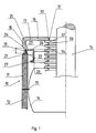
- the vacuum chamber which is only partially shown in cross section in FIG. 1, has an insulating cylinder 10, which is composed of two ceramic cylinders 11 and 12 which take a carrier 13 between them, on the one inside the vacuum chamber located screen 14 is attached.
- an insulating cylinder 10 which is composed of two ceramic cylinders 11 and 12 which take a carrier 13 between them, on the one inside the vacuum chamber located screen 14 is attached.
- the invention is not based on such Designs limited.
- the lid 16 is cup-shaped and has a lid base 17, which is adjoined by a cylindrical wall section 18, at its free end a section 19 with compared to the rest of the lid reduced wall thickness is arranged.
- the length of this section 19 with less Wall thickness is I.
- the reason for this reduction in wall thickness is that the cover 16 according to the embodiment shown in the drawing from a Iron-nickel alloy, which is above a certain temperature Has coefficient of thermal expansion, which differs significantly from that of the ceramic differs.
- the wall thickness must be such that an axial force does not lead to kinking or bulging of the section 19, but on the other hand must be ensured that sufficient elasticity between the cover 16 and the Insulating ceramic 11 is achieved, so that a breakage of the ceramic due to the different Thermal expansion of ceramics and the lid material during the soldering process, which is carried out above said temperature is prevented.
- section 19 is assigned a support ring 20 which is one radial section 21 which between the section 19 and the end face of the Ceramic cylinder 11 is arranged.
- This web 21 is connected to the lid base 17 axially extending web 22, wherein between the inner surface of the Wall section 18 and the web 22 a circumferential gap 23 is formed, which during of the soldering process is filled with solder 24 so that after cooling there between the wall section 18, also called edge 18, and the web 22 a support results.
- the axial length of the web 22 is less than the axial length of the Section 19 with reduced wall thickness, whereby on the one hand an optimal support effect and on the other hand a favorable bendability is achieved to prevent deformation the lid 16 due to excessive external load and a break in the ceramic at To prevent cooling.
- an inwardly directed radial section 25 adjoins the web 22 and an axial portion 26 that faces away from the lid base 17, whereby a shielding element is formed.
- the free end of the radial section 26 is outward L-shaped or U-shaped bent and thereby controls the electrical Field.
- the cover 16 has an opening 30 on which one end 31 one of two Layers 32 and 33 composite bellows 34 connects; the bellows 34 is connected on the one hand vacuum-tight to the cover 16 and on the other hand the both layers 32, 33 welded together vacuum-tight at their ends, so that also prevents gas located within the switchgear housing between the layers can penetrate.
- the inner end of the bellows 34 is not shown in FIG illustrated manner connected vacuum-tight with the contact stem 15.
- FIG. 2 shows another configuration of the cover 40.
- a support plate 41 is soldered, which extends radially and is against this support plate 41 the free end of the edge section 42 of the cover 40 is soldered, the solder 43, 44 Solder fillets form, leading to reinforcement in the area of the connection to the support plate 41 contribute.
- the edge 40 has a section 45 with reduced wall thickness, which corresponds to section 19 of cover 16; the axial length of this section 45 is also designated I here.
- On the disc 41 or plate 41 can Internals can be attached within the vacuum chamber.
- the arrangement according to FIGS. 1 and 2 is preferably designed for a pressure, which is higher than atmospheric pressure.
- 4 to 6 show different configurations of the sealing element between Lid and movable contact stem.
- 4 shows a bellows arrangement 50, which is composed of three bellows layers 51, 52 and 53, which on the End 54 with which they are attached to the lid as well as at the end 55 with which connect them to the movable contact stem by means of a weld seam 56 and 57 are sealed in a vacuum-tight manner, so that gas is prevented from getting inside between the Layers 51 to 53 entered.
- ends 54 and 55 and then solder the bellows assembly in one process step solder the lid and the movable contact stem solder the lid and the movable contact stem.
- 5 is a type of bellows, which consists of several ring parts 60, 61, 62nd and 63 is composed, which are assigned to one another in the manner of cup springs, whereby the individual sections 60 to 63 are frustoconical and each with the outer Edges and the inner edges at 60a, 60b, 61a, 62a alternately vacuum-tight with each other are connected.
- 5 are the ring arrangements 60 to 63 three layers and each have a layer 64, 65 and 66 or 67, 68 and 69 ....
- FIG. 6 shows a membrane-like sealing element 70 that is radial is wave-shaped and aligned and also consists of three layers 71, 72 and 73 is composed, at its outer edge at 74 and at the inner edge at 75 are connected to each other in a vacuum-tight manner.
- the vacuum chamber according to FIG. 7 has, among other things, an insulating cylinder 80 Ceramics, at the free end of which a frustoconical cover section 81 connects, at its inner end, the lid section 81 has a radially extending section 82, on the outside of which a cup-shaped cover 83 connects.
- the lid section 81 can be formed in one piece with the insulating cylinder 80.
Landscapes
- High-Tension Arc-Extinguishing Switches Without Spraying Means (AREA)
Abstract
Description
- Fig. 1
- eine Schnittansicht durch eine erhöhtem Druck ausgesetzte Vakuumkammer,
- Fig. 2 und 3
- unterschiedliche Ausgestaltungen der Verbindung zwischen Deckel und Keramikzylinder,
- Fig. 4 bis 6
- unterschiedliche Ausgestaltungen von Abdichtelementen, und
- Fig. 7
- eine weitere Ausführungsform eines Deckels.
Claims (18)
- Vakuumkammer mit wenigstens einem Isolierzylinder aus Keramik, dessen Stirnenden mittels je eines Deckels verschlossen sind, mit einem an einem beweglichen Kontaktstengel angebrachten beweglichen Kontaktstück und mit einem an einem feststehenden Kontaktstengel angebrachten feststehenden Kontaktstück, die jeweils die Deckel durchgreifen, und mit einem zwischen dem einen Deckel und dem beweglichen Kontaktstengel befestigten, eine Bewegung des Kontaktstengels zulassenden vakuumdichten Abdichtelement, dadurch gekennzeichnet, daß die Deckel (16, 40) napfförmig ausgebildet sind und mit ihrem gegenüber dem übrigen Bereich dünneren freien Rand (19, 45) an dessen jeweiligen Stirnende des benachbarten Isolierzylinders unter Zwischenfügung wenigstens eines Stützringes (20) festgelötet sind, und daß das Abdichtelement (50, 60, 70) mindestens eine Lage, insbesondere zwei Lagen besitzt, die wenigstens an ihren freien Enden, mit denen das Abdichtelement am Deckel (16) und am Kontaktstengel (15) befestigt ist, vakuumdicht miteinander und mit dem Deckel beziehungsweise Kontaktstengel verbunden, insbesondere verschweißt sind.
- Vakuumkammer nach Anspruch 1, dadurch gekennzeichnet, daß das Abdichtelement ein insbesondere mindestens zweilagiger Faltenbalg (50) ist.
- Vakuumkammer nach Anspruch 2, dadurch gekennzeichnet, daß das Abdichtelement eine insbesondere mindestens zweilagige Membran (70) ist.
- Vakuumkammer nach Anspruch 3, dadurch gekennzeichnet, daß das Abdichtelement aus wenigstens zwei tellerfederartig einander zugeordneten kegelstumpfförmigen Membranen (64, 65, 66; 67, 68, 69;......) zusammengesetzt ist, die jeweils vorzugsweise zwei- und mehrlagig sind und an den Stellen, an denen sich die einzelnen Membranen berühren, miteinander vakuumdicht verschweißt sind.
- Vakuumkammer nach einem der Ansprüche 1 bis 4, dadurch gekennzeichnet, daß der Stützring einen Abschnitt (20) aufweist, der in geringem Abstand parallel zur Innenfläche des Randes verläuft, so daß zwischen beiden ein zylindrischer Spalt (23) gebildet ist, der mit Lot ausgefüllt ist.
- Vakuumkammer nach Anspruch 5, dadurch gekennzeichnet, daß die Länge des Abschnittes (19) des Randes, der die dünnere Wandstärke aufweist, so bemessen ist, daß er axiale Knick- oder Beulkräfte und radiale Kräfte aufnimmt, jedoch eine ausreichende Elastizität zum Ausgleich unterschiedlicher Wärmedehnungen von Deckel und Keramik aufweist.
- Vakuumkammer nach Anspruch 6, dadurch gekennzeichnet, daß der Stützring einen L-förmigen Querschnitt aufweist, dessen radialer Steg (21) zwischen dem freien Rand des Deckels (16) und der Stirnfläche des Isolierzylinders (11) und dessen axialer Steg (22) parallel zu und neben der Innenfläche des Randabschnittes (19) verläuft.
- Vakuumkammer nach Anspruch 7, dadurch gekennzeichnet, daß am Stützring (20) ein Schirm (26) angebracht ist, der parallel zum Abdichtelement (34) verläuft.
- Vakuumkammer nach Anspruch 8, dadurch gekennzeichnet, daß der Stützring und der Schirm einstückig sind.
- Vakuumkammer nach einem der Ansprüche 1 bis 4, dadurch gekennzeichnet, daß der Stützring durch hohlkehlartig gestaltetes Lot (43, 44) zwischen der Innen- und/oder Außenfläche des Randes des Deckels (40) und der Stirnkante des Isolierzylinders angeordnet und ausgebildet ist, wobei das Lot einen zur Aufnahme von Druckkräfte ausreichenden Bereich der Außen- bzw. Innenfläche des Wandabschnittes (19) überdeckt.
- Vakuumkammer nach Anspruch 10, dadurch gekennzeichnet, daß der freie Rand des Deckels unmittelbar auf die Stirnkante des Isolierzylinders (11) aufgelötet ist.
- Vakuumkammer nach Anspruch 10, dadurch gekennzeichnet, daß der freie Rand des Deckels unter Zwischenfügung einer radial verlaufenden Ringplatte aus Kupfer befestigt ist.
- Vakuumkammer nach Anspruch 12, dadurch gekennzeichnet, daß die Ringplatte ins Innere der Vakuumkammer ragt und zur Halterung weiterer Komponenten, beispielsweise eines Schirms, dient.
- Vakuumkammer nach einem der vorherigen Ansprüche, dadurch gekennzeichnet, daß der Deckel aus Stahl besteht.
- Vakuumkammer nach einem der vorherigen Ansprüche, dadurch gekennzeichnet, daß der Stützring aus Kupfer besteht.
- Vakuumkammer nach einem der Ansprüche 1 bis 4, dadurch gekennzeichnet, daß ein Deckel vorgesehen ist, der teilweise aus Keramik gebildet ist, an dem ein napfförmiger Deckelteil aus Stahl angeschlossen ist.
- Vakuumkammer nach Anspruch 16, dadurch gekennzeichnet, daß der keramische Deckelabschnitt kegelstumpf- oder bogenförmig ausgebildet ist, an dessen Rand mit geringerem Durchmesser ein radialer Abschnitt anschließt, an dem der Deckelabschnitt aus Metall befestigt ist.
- Vakuumkammer nach Anspruch 17, dadurch gekennzeichnet, daß der keramische Deckelabschnitt am Isolierzylinder angeformt ist.
Applications Claiming Priority (4)
| Application Number | Priority Date | Filing Date | Title |
|---|---|---|---|
| DE19926369 | 1999-06-10 | ||
| DE19926369 | 1999-06-10 | ||
| DE10007907A DE10007907C2 (de) | 1999-06-10 | 2000-02-21 | Vakuumschaltkammer |
| DE10007907 | 2000-02-21 |
Publications (3)
| Publication Number | Publication Date |
|---|---|
| EP1059650A2 true EP1059650A2 (de) | 2000-12-13 |
| EP1059650A3 EP1059650A3 (de) | 2002-07-31 |
| EP1059650B1 EP1059650B1 (de) | 2004-04-21 |
Family
ID=26004451
Family Applications (1)
| Application Number | Title | Priority Date | Filing Date |
|---|---|---|---|
| EP00111230A Expired - Lifetime EP1059650B1 (de) | 1999-06-10 | 2000-05-25 | Vakuumkammer |
Country Status (2)
| Country | Link |
|---|---|
| US (1) | US6308857B1 (de) |
| EP (1) | EP1059650B1 (de) |
Cited By (5)
| Publication number | Priority date | Publication date | Assignee | Title |
|---|---|---|---|---|
| JP2010501992A (ja) * | 2006-09-01 | 2010-01-21 | アーベーベー テクノロジー アクチエンゲゼルシャフト | 中電圧切換え装置のための真空切換え室 |
| WO2010086236A1 (de) * | 2009-01-30 | 2010-08-05 | Siemens Aktiengesellschaft | Vakuumschaltröhre |
| US8227720B2 (en) | 2008-06-30 | 2012-07-24 | Hitachi, Ltd. | Vacuum switch and vacuum switchgear |
| WO2019115177A1 (de) * | 2017-12-11 | 2019-06-20 | Siemens Aktiengesellschaft | Schirmelement für eine vakuumschaltröhre |
| CN111448634A (zh) * | 2017-12-11 | 2020-07-24 | 西门子股份公司 | 耐过压的真空开关管 |
Families Citing this family (5)
| Publication number | Priority date | Publication date | Assignee | Title |
|---|---|---|---|---|
| NL1020347C2 (nl) * | 2002-04-09 | 2003-10-13 | Holec Holland Nv | Keramische buis voor vacuümonderbreker. Keramische buis voor vacuümonderbreker. |
| US6820389B1 (en) * | 2003-03-20 | 2004-11-23 | Valmont Industries, Inc. | Support pole having a traffic signal support arm attached thereto |
| US9352845B1 (en) * | 2012-02-09 | 2016-05-31 | The Boeing Company | Bladders, storage containers, and aircraft fuel systems |
| CN112103128A (zh) * | 2020-08-11 | 2020-12-18 | 平高集团有限公司 | 真空灭弧室筒体、真空灭弧室屏蔽罩及真空灭弧室 |
| JP2023154158A (ja) * | 2022-04-06 | 2023-10-19 | 三菱電機株式会社 | 真空バルブ |
Family Cites Families (13)
| Publication number | Priority date | Publication date | Assignee | Title |
|---|---|---|---|---|
| US884450A (en) * | 1907-04-23 | 1908-04-14 | Stephen Marshall Wright | Metallic barrel. |
| US1483293A (en) * | 1919-01-10 | 1924-02-12 | Hydraulic Pressed Steel Co | Sheet-metal barrel |
| US2164660A (en) * | 1936-10-30 | 1939-07-04 | Petroleum Iron Works Company O | Tank reinforcing ring |
| US3616958A (en) * | 1969-04-16 | 1971-11-02 | Orson L Mitchell | Separable pressure tank apparatus |
| US4071727A (en) * | 1976-05-06 | 1978-01-31 | General Electric Company | Vacuum-type circuit interrupter with means for protecting its bellows against mechanical damage |
| NL178680C (nl) * | 1979-03-05 | 1986-05-01 | Hazemeijer Bv | Werkwijze voor het tot stand brengen van een stompe hardsoldeerverbinding tussen metaal en keramisch materiaal. |
| JPS6065955A (ja) * | 1983-09-17 | 1985-04-15 | Mitsubishi Electric Corp | ベロ−ズ |
| GB2195431B (en) * | 1986-09-22 | 1990-01-17 | Baj Ltd | Dual gas pressure vessel |
| DE3931774A1 (de) * | 1989-09-23 | 1991-04-04 | Calor Emag Elektrizitaets Ag | Verfahren zur herstellung einer vakuumschaltkammer |
| DE4319910C2 (de) * | 1992-06-17 | 2000-04-27 | Isi Metallwarenfabrik Ges M B | Wiederbefüllbare Druckgaskapsel |
| US5427268A (en) * | 1993-06-16 | 1995-06-27 | Battelle Memorial Institute | Ceramic pressure housing with metal endcaps |
| DE19701763C1 (de) * | 1997-01-07 | 1998-07-16 | Siemens Ag | Elektrischer Leistungsschalter mit einem Faltenbalg |
| AU737661B2 (en) * | 1997-11-27 | 2001-08-23 | Nihon Seikan Kabushiki Kaisha | Metallic can and method of manufacture of same, and can cover with integral scraper |
-
2000
- 2000-05-25 EP EP00111230A patent/EP1059650B1/de not_active Expired - Lifetime
- 2000-06-12 US US09/592,298 patent/US6308857B1/en not_active Expired - Fee Related
Cited By (6)
| Publication number | Priority date | Publication date | Assignee | Title |
|---|---|---|---|---|
| JP2010501992A (ja) * | 2006-09-01 | 2010-01-21 | アーベーベー テクノロジー アクチエンゲゼルシャフト | 中電圧切換え装置のための真空切換え室 |
| US8227720B2 (en) | 2008-06-30 | 2012-07-24 | Hitachi, Ltd. | Vacuum switch and vacuum switchgear |
| WO2010086236A1 (de) * | 2009-01-30 | 2010-08-05 | Siemens Aktiengesellschaft | Vakuumschaltröhre |
| WO2019115177A1 (de) * | 2017-12-11 | 2019-06-20 | Siemens Aktiengesellschaft | Schirmelement für eine vakuumschaltröhre |
| CN111448634A (zh) * | 2017-12-11 | 2020-07-24 | 西门子股份公司 | 耐过压的真空开关管 |
| US11342142B2 (en) | 2017-12-11 | 2022-05-24 | Siemens Aktiengesellschaft | Shield element for a vacuum interrupter |
Also Published As
| Publication number | Publication date |
|---|---|
| US6308857B1 (en) | 2001-10-30 |
| EP1059650A3 (de) | 2002-07-31 |
| EP1059650B1 (de) | 2004-04-21 |
Similar Documents
| Publication | Publication Date | Title |
|---|---|---|
| DE3616330C2 (de) | ||
| EP1059650B1 (de) | Vakuumkammer | |
| DE3230091A1 (de) | Druckgasisolierter stromwandler | |
| DE3709585C2 (de) | Vakuumdichtes Gehäuse für Schaltkreisunterbrecher | |
| EP0335114B1 (de) | Vakuumschaltkammer | |
| DE10007907C2 (de) | Vakuumschaltkammer | |
| EP0685027B1 (de) | Elektrisch isolierende gasdichte durchführung mindestens eines elektrischen leiters durch einen metallischen mantel | |
| DE602005001955T2 (de) | Befestigungsvorrichtung für einen Schutzschirm in einem elektrischen Schalter, insbesondere einem Vakuumschalter. | |
| EP0660354B1 (de) | Vakuumschaltkammer | |
| DE102007022875B4 (de) | Gehäuse für eine Vakuumschaltröhre und Vakuumschaltröhre | |
| DE102016209577A1 (de) | Leistungsmodul | |
| DE102021210795A1 (de) | Schaltgerät mit einem Faltenbalg | |
| DE2638252A1 (de) | Vakuumschalter fuer hochspannungsanwendungen | |
| DE3829888C2 (de) | ||
| DE29717489U1 (de) | Röhre zur Verwendung im Mittelspannungs- und Hochspannungsbereich | |
| DE1790217A1 (de) | Bogenloeschkammer fuer Vakuumschaltgeraete | |
| DE4418649A1 (de) | Elektronenstrahlröhren | |
| DE19713478C1 (de) | Vakuumschaltröhre mit einem zwischen zwei Isolatoren angeordneten metallenen Gehäuseteil | |
| DE19910119A1 (de) | Vakuumkammer | |
| DE102021106992A1 (de) | Montageverfahren eines Gassensors und eines rohrförmigen Körpers | |
| WO2025056157A1 (de) | Vakuumschaltröhre und vakuumschalter | |
| DE2725092A1 (de) | Vakuumschalter | |
| DE3803778A1 (de) | Vakuumschaltkammer | |
| DE19715198B4 (de) | Vakuumventil | |
| DE102021210859A1 (de) | Gehäuse für eine Vakuumschaltröhre |
Legal Events
| Date | Code | Title | Description |
|---|---|---|---|
| PUAI | Public reference made under article 153(3) epc to a published international application that has entered the european phase |
Free format text: ORIGINAL CODE: 0009012 |
|
| AK | Designated contracting states |
Kind code of ref document: A2 Designated state(s): AT BE CH CY DE DK ES FI FR GB GR IE IT LI LU MC NL PT SE |
|
| AX | Request for extension of the european patent |
Free format text: AL;LT;LV;MK;RO;SI |
|
| PUAL | Search report despatched |
Free format text: ORIGINAL CODE: 0009013 |
|
| AK | Designated contracting states |
Kind code of ref document: A3 Designated state(s): AT BE CH CY DE DK ES FI FR GB GR IE IT LI LU MC NL PT SE |
|
| AX | Request for extension of the european patent |
Free format text: AL;LT;LV;MK;RO;SI |
|
| 17P | Request for examination filed |
Effective date: 20030118 |
|
| AKX | Designation fees paid |
Designated state(s): DE FR IT |
|
| 17Q | First examination report despatched |
Effective date: 20030530 |
|
| GRAP | Despatch of communication of intention to grant a patent |
Free format text: ORIGINAL CODE: EPIDOSNIGR1 |
|
| GRAS | Grant fee paid |
Free format text: ORIGINAL CODE: EPIDOSNIGR3 |
|
| RAP1 | Party data changed (applicant data changed or rights of an application transferred) |
Owner name: ABB TECHNOLOGY AG |
|
| GRAA | (expected) grant |
Free format text: ORIGINAL CODE: 0009210 |
|
| AK | Designated contracting states |
Kind code of ref document: B1 Designated state(s): DE FR IT |
|
| REG | Reference to a national code |
Ref country code: IE Ref legal event code: FG4D Free format text: GERMAN |
|
| REF | Corresponds to: |
Ref document number: 50006118 Country of ref document: DE Date of ref document: 20040527 Kind code of ref document: P |
|
| ET | Fr: translation filed | ||
| REG | Reference to a national code |
Ref country code: IE Ref legal event code: FD4D |
|
| PLBE | No opposition filed within time limit |
Free format text: ORIGINAL CODE: 0009261 |
|
| STAA | Information on the status of an ep patent application or granted ep patent |
Free format text: STATUS: NO OPPOSITION FILED WITHIN TIME LIMIT |
|
| 26N | No opposition filed |
Effective date: 20050124 |
|
| PGFP | Annual fee paid to national office [announced via postgrant information from national office to epo] |
Ref country code: IT Payment date: 20070524 Year of fee payment: 8 |
|
| PG25 | Lapsed in a contracting state [announced via postgrant information from national office to epo] |
Ref country code: IT Free format text: LAPSE BECAUSE OF NON-PAYMENT OF DUE FEES Effective date: 20080525 |
|
| PGFP | Annual fee paid to national office [announced via postgrant information from national office to epo] |
Ref country code: FR Payment date: 20120601 Year of fee payment: 13 |
|
| REG | Reference to a national code |
Ref country code: FR Ref legal event code: ST Effective date: 20140131 |
|
| PG25 | Lapsed in a contracting state [announced via postgrant information from national office to epo] |
Ref country code: FR Free format text: LAPSE BECAUSE OF NON-PAYMENT OF DUE FEES Effective date: 20130531 |
|
| REG | Reference to a national code |
Ref country code: DE Ref legal event code: R081 Ref document number: 50006118 Country of ref document: DE Owner name: ABB SCHWEIZ AG, CH Free format text: FORMER OWNER: ABB TECHNOLOGY AG, ZUERICH, CH |
|
| PGFP | Annual fee paid to national office [announced via postgrant information from national office to epo] |
Ref country code: DE Payment date: 20190521 Year of fee payment: 20 |
|
| REG | Reference to a national code |
Ref country code: DE Ref legal event code: R071 Ref document number: 50006118 Country of ref document: DE |