EP1057963A2 - Führungseinrichtung für Schiebetürelemente eines Möbels - Google Patents
Führungseinrichtung für Schiebetürelemente eines Möbels Download PDFInfo
- Publication number
- EP1057963A2 EP1057963A2 EP00104061A EP00104061A EP1057963A2 EP 1057963 A2 EP1057963 A2 EP 1057963A2 EP 00104061 A EP00104061 A EP 00104061A EP 00104061 A EP00104061 A EP 00104061A EP 1057963 A2 EP1057963 A2 EP 1057963A2
- Authority
- EP
- European Patent Office
- Prior art keywords
- guide
- guide rail
- sliding door
- guide device
- fastening groove
- Prior art date
- Legal status (The legal status is an assumption and is not a legal conclusion. Google has not performed a legal analysis and makes no representation as to the accuracy of the status listed.)
- Granted
Links
Images



Classifications
-
- E—FIXED CONSTRUCTIONS
- E05—LOCKS; KEYS; WINDOW OR DOOR FITTINGS; SAFES
- E05F—DEVICES FOR MOVING WINGS INTO OPEN OR CLOSED POSITION; CHECKS FOR WINGS; WING FITTINGS NOT OTHERWISE PROVIDED FOR, CONCERNED WITH THE FUNCTIONING OF THE WING
- E05F5/00—Braking devices, e.g. checks; Stops; Buffers
- E05F5/003—Braking devices, e.g. checks; Stops; Buffers for sliding wings
-
- E—FIXED CONSTRUCTIONS
- E05—LOCKS; KEYS; WINDOW OR DOOR FITTINGS; SAFES
- E05D—HINGES OR SUSPENSION DEVICES FOR DOORS, WINDOWS OR WINGS
- E05D15/00—Suspension arrangements for wings
- E05D15/06—Suspension arrangements for wings for wings sliding horizontally more or less in their own plane
- E05D15/08—Suspension arrangements for wings for wings sliding horizontally more or less in their own plane consisting of two or more independent parts movable each in its own guides
-
- E—FIXED CONSTRUCTIONS
- E05—LOCKS; KEYS; WINDOW OR DOOR FITTINGS; SAFES
- E05D—HINGES OR SUSPENSION DEVICES FOR DOORS, WINDOWS OR WINGS
- E05D15/00—Suspension arrangements for wings
- E05D15/06—Suspension arrangements for wings for wings sliding horizontally more or less in their own plane
- E05D15/0621—Details, e.g. suspension or supporting guides
- E05D15/0626—Details, e.g. suspension or supporting guides for wings suspended at the top
- E05D15/063—Details, e.g. suspension or supporting guides for wings suspended at the top on wheels with fixed axis
-
- E—FIXED CONSTRUCTIONS
- E05—LOCKS; KEYS; WINDOW OR DOOR FITTINGS; SAFES
- E05D—HINGES OR SUSPENSION DEVICES FOR DOORS, WINDOWS OR WINGS
- E05D15/00—Suspension arrangements for wings
- E05D15/06—Suspension arrangements for wings for wings sliding horizontally more or less in their own plane
- E05D15/0621—Details, e.g. suspension or supporting guides
- E05D15/0626—Details, e.g. suspension or supporting guides for wings suspended at the top
- E05D15/0652—Tracks
-
- E—FIXED CONSTRUCTIONS
- E05—LOCKS; KEYS; WINDOW OR DOOR FITTINGS; SAFES
- E05D—HINGES OR SUSPENSION DEVICES FOR DOORS, WINDOWS OR WINGS
- E05D15/00—Suspension arrangements for wings
- E05D15/06—Suspension arrangements for wings for wings sliding horizontally more or less in their own plane
- E05D15/0621—Details, e.g. suspension or supporting guides
- E05D15/066—Details, e.g. suspension or supporting guides for wings supported at the bottom
- E05D15/0665—Details, e.g. suspension or supporting guides for wings supported at the bottom on wheels with fixed axis
-
- E—FIXED CONSTRUCTIONS
- E05—LOCKS; KEYS; WINDOW OR DOOR FITTINGS; SAFES
- E05Y—INDEXING SCHEME ASSOCIATED WITH SUBCLASSES E05D AND E05F, RELATING TO CONSTRUCTION ELEMENTS, ELECTRIC CONTROL, POWER SUPPLY, POWER SIGNAL OR TRANSMISSION, USER INTERFACES, MOUNTING OR COUPLING, DETAILS, ACCESSORIES, AUXILIARY OPERATIONS NOT OTHERWISE PROVIDED FOR, APPLICATION THEREOF
- E05Y2201/00—Constructional elements; Accessories therefor
- E05Y2201/60—Suspension or transmission members; Accessories therefor
- E05Y2201/606—Accessories therefor
- E05Y2201/61—Cooperation between suspension or transmission members
- E05Y2201/612—Cooperation between suspension or transmission members between carriers and rails
- E05Y2201/614—Anti-derailing means
-
- E—FIXED CONSTRUCTIONS
- E05—LOCKS; KEYS; WINDOW OR DOOR FITTINGS; SAFES
- E05Y—INDEXING SCHEME ASSOCIATED WITH SUBCLASSES E05D AND E05F, RELATING TO CONSTRUCTION ELEMENTS, ELECTRIC CONTROL, POWER SUPPLY, POWER SIGNAL OR TRANSMISSION, USER INTERFACES, MOUNTING OR COUPLING, DETAILS, ACCESSORIES, AUXILIARY OPERATIONS NOT OTHERWISE PROVIDED FOR, APPLICATION THEREOF
- E05Y2201/00—Constructional elements; Accessories therefor
- E05Y2201/60—Suspension or transmission members; Accessories therefor
- E05Y2201/622—Suspension or transmission members elements
- E05Y2201/684—Rails; Tracks
-
- E—FIXED CONSTRUCTIONS
- E05—LOCKS; KEYS; WINDOW OR DOOR FITTINGS; SAFES
- E05Y—INDEXING SCHEME ASSOCIATED WITH SUBCLASSES E05D AND E05F, RELATING TO CONSTRUCTION ELEMENTS, ELECTRIC CONTROL, POWER SUPPLY, POWER SIGNAL OR TRANSMISSION, USER INTERFACES, MOUNTING OR COUPLING, DETAILS, ACCESSORIES, AUXILIARY OPERATIONS NOT OTHERWISE PROVIDED FOR, APPLICATION THEREOF
- E05Y2201/00—Constructional elements; Accessories therefor
- E05Y2201/60—Suspension or transmission members; Accessories therefor
- E05Y2201/622—Suspension or transmission members elements
- E05Y2201/688—Rollers
-
- E—FIXED CONSTRUCTIONS
- E05—LOCKS; KEYS; WINDOW OR DOOR FITTINGS; SAFES
- E05Y—INDEXING SCHEME ASSOCIATED WITH SUBCLASSES E05D AND E05F, RELATING TO CONSTRUCTION ELEMENTS, ELECTRIC CONTROL, POWER SUPPLY, POWER SIGNAL OR TRANSMISSION, USER INTERFACES, MOUNTING OR COUPLING, DETAILS, ACCESSORIES, AUXILIARY OPERATIONS NOT OTHERWISE PROVIDED FOR, APPLICATION THEREOF
- E05Y2600/00—Mounting or coupling arrangements for elements provided for in this subclass
- E05Y2600/10—Adjustable
-
- E—FIXED CONSTRUCTIONS
- E05—LOCKS; KEYS; WINDOW OR DOOR FITTINGS; SAFES
- E05Y—INDEXING SCHEME ASSOCIATED WITH SUBCLASSES E05D AND E05F, RELATING TO CONSTRUCTION ELEMENTS, ELECTRIC CONTROL, POWER SUPPLY, POWER SIGNAL OR TRANSMISSION, USER INTERFACES, MOUNTING OR COUPLING, DETAILS, ACCESSORIES, AUXILIARY OPERATIONS NOT OTHERWISE PROVIDED FOR, APPLICATION THEREOF
- E05Y2800/00—Details, accessories and auxiliary operations not otherwise provided for
- E05Y2800/73—Multiple functions
-
- E—FIXED CONSTRUCTIONS
- E05—LOCKS; KEYS; WINDOW OR DOOR FITTINGS; SAFES
- E05Y—INDEXING SCHEME ASSOCIATED WITH SUBCLASSES E05D AND E05F, RELATING TO CONSTRUCTION ELEMENTS, ELECTRIC CONTROL, POWER SUPPLY, POWER SIGNAL OR TRANSMISSION, USER INTERFACES, MOUNTING OR COUPLING, DETAILS, ACCESSORIES, AUXILIARY OPERATIONS NOT OTHERWISE PROVIDED FOR, APPLICATION THEREOF
- E05Y2900/00—Application of doors, windows, wings or fittings thereof
- E05Y2900/20—Application of doors, windows, wings or fittings thereof for furniture, e.g. cabinets
Definitions
- the present invention relates to a guide device for sliding door elements a piece of furniture, comprising a guide rail which can be fixed on the piece of furniture and at least one guide part which can be fastened on the sliding door side, preferably in the form a roller.
- Guide devices of the generic type are in many embodiments known.
- a Guide device in the lower one and another guide device in the upper one End area of the sliding door element needed.
- To fix the sliding door element compared to the guide rails are usually at least two guide parts as well as in the lower and in the upper area.
- the present invention has for its object a guide device to create the generic type that is easy and inexpensive to manufacture and on can be fixed in various ways on the front of a furniture body.
- the guide rail of the guide device can be attached to the in various ways
- the front of a furniture carcass can be set because of that in the middle cross-sectional area arranged, C-shaped fastening groove ideal for this forms.
- the guide rail can be attached to a furniture body using dowels and eccentric fittings be fastened, the dowels with a in the C-shaped fastening groove engaging head are provided. With this type of attachment, the C-shaped Fastening groove with its open side towards the furniture body.
- the open side of the C-shaped mounting groove can then be used as required Cover rail are closed.
- this can be in the lower as well as in the upper area of a Sliding door element can be used to guide this sliding door element.
- a further sliding door element can be located below a sliding door element be provided, which is then in its upper area in the lower Guide groove of the guide rail also used to guide the upper sliding door element can be performed.
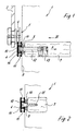
- Reference numeral 1 designates a furniture body in general, with a sliding door element 2 is equipped in the form of a glass door.
- This sliding door element 2 is carried and guided by a guide device 3, which essentially consist of a guide rail 4 and a guide part 5, here in the form of a roller 6.
- the guide rail 4 is fixed on the furniture body 1, namely on an intermediate floor 7.
- This intermediate floor 7 jumps against the front surface 8 of the Furniture body 1 slightly back so that to compensate for the difference between the front edge of the intermediate floor 7 and the front surface 8 of the furniture body 1 a spacer 9 between the intermediate floor 7 and the guide rail 4th is provided.
- the guide rail 4 is approximately C-shaped in its central cross-sectional area Fastening groove 10 equipped.
- the guide rail 4 is located above and below this fastening groove 10 Guide grooves 11 provided.
- the fastening of the guide rail 4 on the furniture body 1 - here specifically on the intermediate floor 7 - takes place via a dowel 12 and an eccentric fitting 13, wherein the dowel 12 with one held in the fastening groove 10 of the guide rail 4 Head 14 is equipped.
- the eccentric fitting 13 By turning the eccentric fitting 13, the Dowels 12 are tightened in a manner known per se in the direction of arrow A in FIG and thus the guide rail 4 firmly against the spacer 9 and thus also the intermediate floor 7 are tightened.
- Figure 2 shows another mounting option for a guide rail 4 one guide device according to the invention.
- FIG. 2 there is also between the intermediate floor 7 of the furniture body 1 and the guide rail 4, a spacer 9 is provided.
- This spacer 9 is equipped with a metric internal thread.
- Guide rail 4 engaging fastening screw 15 screwed in partially is provided with a metric threaded section 16.
- the spacer 9 is screwed on and can Set the fastening screw 15 with respect to the intermediate floor 7 in the direction the guide rail 4 are screwed, so that a flawless here Fixing the mounting rail 4 is reached.
- the guide rail 4 has the open side of the fastening groove 10 in the direction of the furniture body 1.
- the guide rail 4 can also be replaced by a simple one Fixing screws 15a on the furniture side, which are then determined by the Pass the fastening groove 10 through the web area delimiting the bottom.
- the open side of the fastening groove 10 faces the front of the furniture body 1 and is expedient after assembly a cover rail 17 closed.
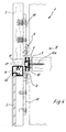
- Figure 4 also shows an example that a guide rail 4 for guidance two superposed sliding door elements 2 can be used, whereby then the roller 6 of the upper sliding door element 2 into the upper guide groove 11 and the roller 6 of the lower sliding door element 2 corresponding to the lower guide groove 11 of the guide rail 4 engages.
- FIG. 4 exemplifies that the sliding door elements 2 can be made of different materials, so is the embodiment 4, the upper sliding door element 2 made of wood, while the lower sliding door element 2 consists essentially of a glass plate, which in a running frame 18 is held.
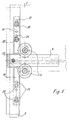
- FIG. 5 shows bracket 19, which on the one hand, the rollers 6 of the guide device wear and on the other hand attached to the back of the sliding door elements 2 are.
- the screws 20 to fix this bracket 19 to the Sliding door elements 2 passed through slots 21 of the bracket 19, so that after loosening the screws 20 by moving the bracket 19 a easy and easy disassembly of the sliding door elements 2 is possible.
- FIG. 6 shows an embodiment in which two sliding door elements 2 overlap are guided on the guide devices 4 according to the invention.
- the sliding door element lying directly facing the furniture body 1 2 guided in the lower guide grooves 11 of the respective guide rail 4 and the sliding door element 2 further away from the furniture body 1 is included its rollers 6 in the respective upper or lower guide groove 11 of the respective Guide rail 4 out.
- the sliding door element 2 facing away from the furniture body 1 can be s in one lower area also with a simple slide rail 22 in the lower guide groove 4 engage the lower guide rail 4, as clearly shown in FIG. 6.
- Figures 3 and 5 exemplify that the guide rail 4 on the front can each be closed by cover caps 23, which at the same time Can form end stops for the sliding door elements 2.
- the guide rail 4 can be used on a furniture body. You can do this End caps 23 pushed onto the guide rail 4 and, for example, by Screws to the furniture body are fixed, so that a fastening at the same time the guide rail 4 is given. Such a solution is particularly in To be considered if the guide rail 4 is not too great overall length having.
- Figures 7 and 8 show one possibility, simultaneously with the fastening means to fix the guide rail 4 of a guide device according to the invention 3 also an adjustment of this guide rail 4 in the horizontal direction perform.
- a dowel 12 and an eccentric fitting 13 are provided.
- the area of this dowel 12 passing through the open side of the fastening groove 10 or the head 14 of this dowel 12 is eccentric with respect to the longitudinal axis of the dowel formed so that by rotating the dowel 12 by means of a tool 24 a height adjustment of the guide rail 4 can be reached.
- the shaft of the dowel 12 is polygonal and penetrates the polygonal recess 25 of a spacer 9, which on the outside, for example, as Formed hexagon and thus slightly rotated by a corresponding tool 24 can be.
- the fastener can ultimately as Adjustment device for the guide rail 4 can be used.
- the end caps 23 can in the stop area of the sliding door elements 2 for noise reduction be provided with a damping coating 26, as shown in FIG. 3, this damping pad 26 made of rubber, felt, plastic or the like can exist. Alternatively, however, a resilient damping element can also be used be integrally formed on the respective end cap 23.
Landscapes
- Engineering & Computer Science (AREA)
- Mechanical Engineering (AREA)
- Support Devices For Sliding Doors (AREA)
- Power-Operated Mechanisms For Wings (AREA)
Abstract
Description
- Figur 1
- einen vertikalen Teilschnitt durch ein Möbel mit einem Schiebetürelement mit erfindungsgemäßer Führungseinrichtung,
- Figur 2
- einen Vertikalschnitt durch eine möbelkorpusseitig festgelegte Führungsschiene nach einem weiteren Ausführungsbeispiel der Erfindung,
- Figur 3
- eine Teilansicht in Richtung des Pfeiles III in Figur 1, gezeigt ohne den in Figur 1 dargestellten Zwischenboden des Möbelkorpus,
- Figur 4
- einen schematisch dargestellten, vertikalen Teilschnitt durch ein Möbel mit übereinanderliegenden Schiebetürelementen mit einer erfindungsgsemäßen Führungseinrichtung,
- Figur 5
- eine Ansicht in Richtung des Pfeiles V in Figur 4, dargestellt ohne den Zwischenboden gemäß Figur 4,
- Figur 6
- einen Vertikalschnitt durch ein Möbel mit zwei einander überlappenden Schiebetürelementen, die an erfindungsgemäßen Führungseinrichtungen geführt sind,
- Figur 7
- eine schematische, perspektivische Sprengbild-Darstellung einer besonders vorteilhaften Befestigungsmöglichkeit der Führungsschiene einer erfindungsgemäßen Führungseinrichtung,
- Figur 8
- einen Vertikalschnitt durch eine korpusseitig befestigte Führungsschiene gemäß Figur 7.
Claims (10)
- Führungseinrichtung für Schiebetürelemente eines Möbels, umfassend eine möbelseitig festlegbare Führungsschiene und mindestens ein schiebetürseitig befestigbares Führungsteil, vorzugsweise in Form einer Laufrolle, dadurch gekennzeichnet, daß die Führungsschiene (4) in ihrem mittleren Querschnittsbereich mit einer C-förmigen Befestigungsnut (10) zur Aufnahme von Befestigungsmitteln versehen ist und sowohl unterhalb wie auch oberhalb der Befestigungsnut (10) mit Führungsnuten (11) zur Führung von Führungsteilen wie Laufrollen (6) oder Gleitstücken ausgestattet ist.
- Führungseinrichtung nach Anspruch 1, dadurch gekennzeichnet, daß die Befestigungsmittel für die Führungsschiene (4) aus Dübeln (12) und Exzenterbeschlägen (13) bestehen, wobei die Dübel (12) an einem ihrer stirnseitigen Enden mit einem in die Befestigungsnut (10) eingreifenden Kopf (14) und an ihrem anderen stirnseitigen Ende mit einem in einem möbelseitig festlegbaren Exzenterbeschlag (13) eingreifenden Spannkopf versehen sind.
- Führungseinrichtung nach Anspruch 1, dadurch gekennzeichnet, daß die Befestigungsmittel aus Befestigungsschrauben (15, 15a) bestehen, welche durch den die Befestigungsnut (10) bodenseitig begrenzenden Stegbereich hindurchtreten.
- Führungseinrichtung nach Anspruch 1, dadurch gekennzeichnet, daß die Befestigungsmittel aus Schrauben (15) bestehen, die mit einem Schneidgewindeabschnitt unmittelbar in das Material des Möbels einschraubbar sind und an ihrem gegenüberliegenden Endbereich mit einem in die Befestigungsnut (10) eingreifenden Kopf (14) versehen sind, wobei zwischen dem Kopf (14) und dem Schneidgewindeabschnitt ein mit metrischem Gewinde versehener Abschnitt (16) vorgesehen ist, auf dem ein mit metrischem Innengewinde versehenes Distanzstück (9) aufgeschraubt ist.
- Führungseinrichtung nach Anspruch 2, dadurch gekennzeichnet, daß der Kopf (14) oder der die offene Seite der Befestigungsnut (10) durchtretende Bereich des Dübels (12) gegenüber der Dübellängsachse exzentrisch angeordnet ist.
- Führungseinrichtung nach Anspruch 5, dadurch gekennzeichnet, daß der Schaft des Dübels (12) mehrkantig ausgebildet ist und eine entsprechende Mehrkantausnehmung (25) eines Distanzstückes (9) durchtritt, welches außenseitig mehrkantig begrenzt ist.
- Führungseinrichtung nach einem oder mehreren der vorhergehenden Ansprüche, dadurch gekennzeichnet, daß die Führungsschiene (4) stirnseitig durch Endkappen (23) geschlossen ist.
- Führungseinrichtung nach Anspruch 7, dadurch gekennzeichnet, daß die Endkappen (23) mit Anschlagbereichen für ein Schiebetürelement (2) ausgestattet sind.
- Führungseinrichtung nach Anspruch 8, dadurch gekennzeichnet, daß im Anschlagbereich der Endkappen (23) ein Dämpfungsbelag (26) aus Gummi, Filz, Kunststoff oder dergleichen befestigt ist.
- Führungseinrichtung nach Anspruch 8, dadurch gekennzeichnet, daß im Anschlagbereich der Endkappen (23) ein Dämpfungselement in Form eines einstückig angeformten, federnden Abschnittes vorgesehen ist.
Applications Claiming Priority (2)
| Application Number | Priority Date | Filing Date | Title |
|---|---|---|---|
| DE29907980U | 1999-05-05 | ||
| DE29907980U DE29907980U1 (de) | 1999-05-05 | 1999-05-05 | Führungseinrichtung für Schiebetürelemente eines Möbels |
Publications (3)
| Publication Number | Publication Date |
|---|---|
| EP1057963A2 true EP1057963A2 (de) | 2000-12-06 |
| EP1057963A3 EP1057963A3 (de) | 2002-05-29 |
| EP1057963B1 EP1057963B1 (de) | 2006-04-19 |
Family
ID=8073146
Family Applications (1)
| Application Number | Title | Priority Date | Filing Date |
|---|---|---|---|
| EP00104061A Expired - Lifetime EP1057963B1 (de) | 1999-05-05 | 2000-02-28 | Führungseinrichtung für Schiebetürelemente eines Möbels |
Country Status (3)
| Country | Link |
|---|---|
| EP (1) | EP1057963B1 (de) |
| AT (1) | ATE323819T1 (de) |
| DE (2) | DE29907980U1 (de) |
Cited By (2)
| Publication number | Priority date | Publication date | Assignee | Title |
|---|---|---|---|---|
| DE10119995A1 (de) * | 2001-04-23 | 2002-10-31 | Dorma Gmbh & Co Kg | Halteelement zum Halten einer Führungsschiene für Schiebetüren |
| AT413729B (de) * | 2001-04-23 | 2006-05-15 | Hubert Elmer | Universelle führungseinrichtung für schiebetüren eines möbels |
Families Citing this family (3)
| Publication number | Priority date | Publication date | Assignee | Title |
|---|---|---|---|---|
| ATE521775T1 (de) * | 2009-02-15 | 2011-09-15 | Hawa Ag | Verschiebbares trennelement und vorrichtung |
| DE102009051362A1 (de) | 2009-10-30 | 2011-05-05 | Airbus Operations Gmbh | Staufachmodul mit integralem Versorgungskanal für optimierte Montage |
| DE102009051363A1 (de) * | 2009-10-30 | 2011-05-05 | Airbus Operations Gmbh | Staufachmodul mit beweglichem Staufach |
Family Cites Families (5)
| Publication number | Priority date | Publication date | Assignee | Title |
|---|---|---|---|---|
| US2784444A (en) * | 1954-03-19 | 1957-03-12 | Woodall Industries Inc | Trackway and hanger for a sliding door |
| US5675946A (en) * | 1996-06-07 | 1997-10-14 | Teknion Furniture Systems | Privacy screen for office panelling systems |
| GB2326662B (en) * | 1997-06-24 | 2002-03-13 | Stephen Kenneth Brunton | Lift door |
| EP1020154A3 (de) * | 1999-01-18 | 2002-02-13 | DORMA GmbH + Co. KG | Duschabtrennung |
| DE29905419U1 (de) * | 1999-03-29 | 1999-06-24 | Dorma Gmbh + Co. Kg, 58256 Ennepetal | Duschabtrennung |
-
1999
- 1999-05-05 DE DE29907980U patent/DE29907980U1/de not_active Expired - Lifetime
-
2000
- 2000-02-28 AT AT00104061T patent/ATE323819T1/de not_active IP Right Cessation
- 2000-02-28 DE DE50012590T patent/DE50012590D1/de not_active Expired - Lifetime
- 2000-02-28 EP EP00104061A patent/EP1057963B1/de not_active Expired - Lifetime
Cited By (6)
| Publication number | Priority date | Publication date | Assignee | Title |
|---|---|---|---|---|
| DE10119995A1 (de) * | 2001-04-23 | 2002-10-31 | Dorma Gmbh & Co Kg | Halteelement zum Halten einer Führungsschiene für Schiebetüren |
| WO2002086268A1 (de) | 2001-04-23 | 2002-10-31 | Dorma Gmbh + Co. Kg | Halteelement zum halten einer führungsschiene für schiebetüren |
| DE10119995B4 (de) * | 2001-04-23 | 2004-05-06 | Dorma Gmbh + Co. Kg | Halteelement zum Halten einer Führungsschiene für Schiebetüren |
| AT412895B (de) * | 2001-04-23 | 2005-08-25 | Hubert Elmer | Halteelement zum halten einer führungsschiene für schiebetüren |
| AT413729B (de) * | 2001-04-23 | 2006-05-15 | Hubert Elmer | Universelle führungseinrichtung für schiebetüren eines möbels |
| DE10119996B4 (de) * | 2001-04-23 | 2007-09-27 | Dorma Gmbh + Co. Kg | Universelle Führungseinrichtung für Schiebetüren eines Möbels |
Also Published As
| Publication number | Publication date |
|---|---|
| EP1057963B1 (de) | 2006-04-19 |
| DE29907980U1 (de) | 1999-07-08 |
| DE50012590D1 (de) | 2006-05-24 |
| ATE323819T1 (de) | 2006-05-15 |
| EP1057963A3 (de) | 2002-05-29 |
Similar Documents
| Publication | Publication Date | Title |
|---|---|---|
| AT394081B (de) | Verstellbares tuer- und fensterband | |
| DE29521766U1 (de) | Höhenverstellbares Treppenkantenprofil | |
| DE102007028218B3 (de) | Tür- oder Fensterscharnier | |
| DE68911670T2 (de) | Beschlag für Schiebetüren. | |
| EP1331338B1 (de) | Band für Türen, Fenster und dergleichen | |
| DE2401865A1 (de) | Moebelscharnier | |
| EP0682188B1 (de) | Linearführung | |
| DE2407196A1 (de) | Treibstangenbeschlag fuer fenster, tueren o.dgl., insbesondere kunststoff-fluegelrahmen | |
| CH657415A5 (en) | Sliding door with a holding device | |
| EP1057963B1 (de) | Führungseinrichtung für Schiebetürelemente eines Möbels | |
| DE2657628A1 (de) | Moebelscharnier | |
| DE2655749A1 (de) | Moebelscharnier | |
| EP0940539A2 (de) | Band für Türen, Fenster oder dergleichen | |
| DE2547731B2 (de) | Justiervorrichtung zum ausrichten von tuerrahmen, fensterblendrahmen o.dgl. in einer wandoeffnung | |
| DE20018838U1 (de) | Verstellbare Stopp- und Dämpfungsvorrichtung für Schiebe- und/oder Faltschiebetürelemente | |
| DE3923639C2 (de) | Bodentürschließer für eine Schwenktür | |
| EP0166811A1 (de) | Beschlag für Schiebeflügel | |
| DE3800443C2 (de) | Eckverbindung für die Rahmenkonstruktion einer Dusch- oder Badewannenabtrennung u. dgl. | |
| EP0006439B2 (de) | Vorrichtung zur Stossstellenüberlappung an Stulpschienen | |
| DE2821101A1 (de) | Moebel-auszugfuehrung | |
| DE2848344A1 (de) | Hoeheneinstellvorrichtung an einem starren fahrzeug-schiebedach | |
| EP1716311A1 (de) | Tür mit einem drehbar gelagerten türflügel | |
| DE19734647A1 (de) | Beschlagteil an einem Flügel oder einem festen Rahmen eines Fensters, einer Tür od. dgl. | |
| DE2949539A1 (de) | Aufhaengevorrichtung fuer eine verschiebbare wandtafel einer schiebetrennwand | |
| EP0893556A1 (de) | Sanitärtrennwand |
Legal Events
| Date | Code | Title | Description |
|---|---|---|---|
| PUAI | Public reference made under article 153(3) epc to a published international application that has entered the european phase |
Free format text: ORIGINAL CODE: 0009012 |
|
| AK | Designated contracting states |
Kind code of ref document: A2 Designated state(s): AT BE CH CY DE DK ES FI FR GB GR IE IT LI LU MC NL PT SE |
|
| AX | Request for extension of the european patent |
Free format text: AL;LT;LV;MK;RO;SI |
|
| PUAL | Search report despatched |
Free format text: ORIGINAL CODE: 0009013 |
|
| AK | Designated contracting states |
Kind code of ref document: A3 Designated state(s): AT BE CH CY DE DK ES FI FR GB GR IE IT LI LU MC NL PT SE |
|
| AX | Request for extension of the european patent |
Free format text: AL;LT;LV;MK;RO;SI |
|
| RIC1 | Information provided on ipc code assigned before grant |
Free format text: 7E 06B 3/46 A, 7E 05D 15/06 B |
|
| 17P | Request for examination filed |
Effective date: 20021113 |
|
| AKX | Designation fees paid |
Designated state(s): AT BE CH CY DE DK ES FI FR GB GR IE IT LI LU MC NL PT SE |
|
| 17Q | First examination report despatched |
Effective date: 20030930 |
|
| GRAP | Despatch of communication of intention to grant a patent |
Free format text: ORIGINAL CODE: EPIDOSNIGR1 |
|
| GRAS | Grant fee paid |
Free format text: ORIGINAL CODE: EPIDOSNIGR3 |
|
| GRAA | (expected) grant |
Free format text: ORIGINAL CODE: 0009210 |
|
| AK | Designated contracting states |
Kind code of ref document: B1 Designated state(s): AT BE CH CY DE DK ES FI FR GB GR IE IT LI LU MC NL PT SE |
|
| PG25 | Lapsed in a contracting state [announced via postgrant information from national office to epo] |
Ref country code: IT Free format text: LAPSE BECAUSE OF FAILURE TO SUBMIT A TRANSLATION OF THE DESCRIPTION OR TO PAY THE FEE WITHIN THE PRE;WARNING: LAPSES OF ITALIAN PATENTS WITH EFFECTIVE DATE BEFORE 2007 MAY HAVE OCCURRED AT ANY TIME BEFORE 2007. THE CORRECT EFFECTIVE DATE MAY BE DIFFERENT FROM THE ONE RECORDED.SCRIBED TIME-LIMIT Effective date: 20060419 Ref country code: GB Free format text: LAPSE BECAUSE OF FAILURE TO SUBMIT A TRANSLATION OF THE DESCRIPTION OR TO PAY THE FEE WITHIN THE PRESCRIBED TIME-LIMIT Effective date: 20060419 Ref country code: NL Free format text: LAPSE BECAUSE OF FAILURE TO SUBMIT A TRANSLATION OF THE DESCRIPTION OR TO PAY THE FEE WITHIN THE PRESCRIBED TIME-LIMIT Effective date: 20060419 Ref country code: IE Free format text: LAPSE BECAUSE OF FAILURE TO SUBMIT A TRANSLATION OF THE DESCRIPTION OR TO PAY THE FEE WITHIN THE PRESCRIBED TIME-LIMIT Effective date: 20060419 Ref country code: FI Free format text: LAPSE BECAUSE OF FAILURE TO SUBMIT A TRANSLATION OF THE DESCRIPTION OR TO PAY THE FEE WITHIN THE PRESCRIBED TIME-LIMIT Effective date: 20060419 |
|
| REG | Reference to a national code |
Ref country code: GB Ref legal event code: FG4D Free format text: NOT ENGLISH |
|
| REF | Corresponds to: |
Ref document number: 50012590 Country of ref document: DE Date of ref document: 20060524 Kind code of ref document: P |
|
| REG | Reference to a national code |
Ref country code: IE Ref legal event code: FG4D Free format text: LANGUAGE OF EP DOCUMENT: GERMAN |
|
| REG | Reference to a national code |
Ref country code: CH Ref legal event code: NV Representative=s name: ISLER & PEDRAZZINI AG |
|
| REG | Reference to a national code |
Ref country code: SE Ref legal event code: TRGR |
|
| PG25 | Lapsed in a contracting state [announced via postgrant information from national office to epo] |
Ref country code: DK Free format text: LAPSE BECAUSE OF FAILURE TO SUBMIT A TRANSLATION OF THE DESCRIPTION OR TO PAY THE FEE WITHIN THE PRESCRIBED TIME-LIMIT Effective date: 20060719 |
|
| PG25 | Lapsed in a contracting state [announced via postgrant information from national office to epo] |
Ref country code: ES Free format text: LAPSE BECAUSE OF FAILURE TO SUBMIT A TRANSLATION OF THE DESCRIPTION OR TO PAY THE FEE WITHIN THE PRESCRIBED TIME-LIMIT Effective date: 20060730 |
|
| PG25 | Lapsed in a contracting state [announced via postgrant information from national office to epo] |
Ref country code: PT Free format text: LAPSE BECAUSE OF FAILURE TO SUBMIT A TRANSLATION OF THE DESCRIPTION OR TO PAY THE FEE WITHIN THE PRESCRIBED TIME-LIMIT Effective date: 20060919 |
|
| NLV1 | Nl: lapsed or annulled due to failure to fulfill the requirements of art. 29p and 29m of the patents act | ||
| GBV | Gb: ep patent (uk) treated as always having been void in accordance with gb section 77(7)/1977 [no translation filed] |
Effective date: 20060419 |
|
| REG | Reference to a national code |
Ref country code: IE Ref legal event code: FD4D |
|
| PLBE | No opposition filed within time limit |
Free format text: ORIGINAL CODE: 0009261 |
|
| STAA | Information on the status of an ep patent application or granted ep patent |
Free format text: STATUS: NO OPPOSITION FILED WITHIN TIME LIMIT |
|
| PG25 | Lapsed in a contracting state [announced via postgrant information from national office to epo] |
Ref country code: MC Free format text: LAPSE BECAUSE OF NON-PAYMENT OF DUE FEES Effective date: 20070228 |
|
| 26N | No opposition filed |
Effective date: 20070122 |
|
| EN | Fr: translation not filed | ||
| REG | Reference to a national code |
Ref country code: CH Ref legal event code: PCAR Free format text: ISLER & PEDRAZZINI AG;POSTFACH 1772;8027 ZUERICH (CH) |
|
| BERE | Be: lapsed |
Owner name: HETTICH-HEINZE G.M.B.H. & CO. KG Effective date: 20070228 |
|
| PG25 | Lapsed in a contracting state [announced via postgrant information from national office to epo] |
Ref country code: BE Free format text: LAPSE BECAUSE OF NON-PAYMENT OF DUE FEES Effective date: 20070228 |
|
| PG25 | Lapsed in a contracting state [announced via postgrant information from national office to epo] |
Ref country code: GR Free format text: LAPSE BECAUSE OF FAILURE TO SUBMIT A TRANSLATION OF THE DESCRIPTION OR TO PAY THE FEE WITHIN THE PRESCRIBED TIME-LIMIT Effective date: 20060720 Ref country code: FR Free format text: LAPSE BECAUSE OF FAILURE TO SUBMIT A TRANSLATION OF THE DESCRIPTION OR TO PAY THE FEE WITHIN THE PRESCRIBED TIME-LIMIT Effective date: 20070309 |
|
| PG25 | Lapsed in a contracting state [announced via postgrant information from national office to epo] |
Ref country code: AT Free format text: LAPSE BECAUSE OF NON-PAYMENT OF DUE FEES Effective date: 20070228 |
|
| PG25 | Lapsed in a contracting state [announced via postgrant information from national office to epo] |
Ref country code: FR Free format text: LAPSE BECAUSE OF FAILURE TO SUBMIT A TRANSLATION OF THE DESCRIPTION OR TO PAY THE FEE WITHIN THE PRESCRIBED TIME-LIMIT Effective date: 20060419 |
|
| PG25 | Lapsed in a contracting state [announced via postgrant information from national office to epo] |
Ref country code: LU Free format text: LAPSE BECAUSE OF NON-PAYMENT OF DUE FEES Effective date: 20070228 Ref country code: CY Free format text: LAPSE BECAUSE OF FAILURE TO SUBMIT A TRANSLATION OF THE DESCRIPTION OR TO PAY THE FEE WITHIN THE PRESCRIBED TIME-LIMIT Effective date: 20060419 |
|
| PGFP | Annual fee paid to national office [announced via postgrant information from national office to epo] |
Ref country code: CH Payment date: 20120221 Year of fee payment: 13 |
|
| PGFP | Annual fee paid to national office [announced via postgrant information from national office to epo] |
Ref country code: SE Payment date: 20120221 Year of fee payment: 13 |
|
| REG | Reference to a national code |
Ref country code: CH Ref legal event code: PL |
|
| REG | Reference to a national code |
Ref country code: SE Ref legal event code: EUG |
|
| PG25 | Lapsed in a contracting state [announced via postgrant information from national office to epo] |
Ref country code: CH Free format text: LAPSE BECAUSE OF NON-PAYMENT OF DUE FEES Effective date: 20130228 Ref country code: SE Free format text: LAPSE BECAUSE OF NON-PAYMENT OF DUE FEES Effective date: 20130301 Ref country code: LI Free format text: LAPSE BECAUSE OF NON-PAYMENT OF DUE FEES Effective date: 20130228 |
|
| PGFP | Annual fee paid to national office [announced via postgrant information from national office to epo] |
Ref country code: DE Payment date: 20140220 Year of fee payment: 15 |
|
| PGFP | Annual fee paid to national office [announced via postgrant information from national office to epo] |
Ref country code: IT Payment date: 20140224 Year of fee payment: 15 |
|
| REG | Reference to a national code |
Ref country code: DE Ref legal event code: R119 Ref document number: 50012590 Country of ref document: DE |
|
| PG25 | Lapsed in a contracting state [announced via postgrant information from national office to epo] |
Ref country code: IT Free format text: LAPSE BECAUSE OF NON-PAYMENT OF DUE FEES Effective date: 20150228 |
|
| PG25 | Lapsed in a contracting state [announced via postgrant information from national office to epo] |
Ref country code: DE Free format text: LAPSE BECAUSE OF NON-PAYMENT OF DUE FEES Effective date: 20150901 |