EP1057906B1 - Web producing installation and method - Google Patents
Web producing installation and method Download PDFInfo
- Publication number
- EP1057906B1 EP1057906B1 EP00111172A EP00111172A EP1057906B1 EP 1057906 B1 EP1057906 B1 EP 1057906B1 EP 00111172 A EP00111172 A EP 00111172A EP 00111172 A EP00111172 A EP 00111172A EP 1057906 B1 EP1057906 B1 EP 1057906B1
- Authority
- EP
- European Patent Office
- Prior art keywords
- woven
- profile
- fleece
- measuring device
- plaiter
- Prior art date
- Legal status (The legal status is an assumption and is not a legal conclusion. Google has not performed a legal analysis and makes no representation as to the accuracy of the status listed.)
- Expired - Lifetime
Links
Images

Classifications
-
- D—TEXTILES; PAPER
- D01—NATURAL OR MAN-MADE THREADS OR FIBRES; SPINNING
- D01G—PRELIMINARY TREATMENT OF FIBRES, e.g. FOR SPINNING
- D01G25/00—Lap-forming devices not integral with machines specified above
-
- D—TEXTILES; PAPER
- D01—NATURAL OR MAN-MADE THREADS OR FIBRES; SPINNING
- D01G—PRELIMINARY TREATMENT OF FIBRES, e.g. FOR SPINNING
- D01G23/00—Feeding fibres to machines; Conveying fibres between machines
- D01G23/06—Arrangements in which a machine or apparatus is regulated in response to changes in the volume or weight of fibres fed, e.g. piano motions
-
- D—TEXTILES; PAPER
- D04—BRAIDING; LACE-MAKING; KNITTING; TRIMMINGS; NON-WOVEN FABRICS
- D04H—MAKING TEXTILE FABRICS, e.g. FROM FIBRES OR FILAMENTARY MATERIAL; FABRICS MADE BY SUCH PROCESSES OR APPARATUS, e.g. FELTS, NON-WOVEN FABRICS; COTTON-WOOL; WADDING ; NON-WOVEN FABRICS FROM STAPLE FIBRES, FILAMENTS OR YARNS, BONDED WITH AT LEAST ONE WEB-LIKE MATERIAL DURING THEIR CONSOLIDATION
- D04H1/00—Non-woven fabrics formed wholly or mainly of staple fibres or like relatively short fibres
- D04H1/40—Non-woven fabrics formed wholly or mainly of staple fibres or like relatively short fibres from fleeces or layers composed of fibres without existing or potential cohesive properties
- D04H1/44—Non-woven fabrics formed wholly or mainly of staple fibres or like relatively short fibres from fleeces or layers composed of fibres without existing or potential cohesive properties the fleeces or layers being consolidated by mechanical means, e.g. by rolling
- D04H1/46—Non-woven fabrics formed wholly or mainly of staple fibres or like relatively short fibres from fleeces or layers composed of fibres without existing or potential cohesive properties the fleeces or layers being consolidated by mechanical means, e.g. by rolling by needling or like operations to cause entanglement of fibres
-
- D—TEXTILES; PAPER
- D04—BRAIDING; LACE-MAKING; KNITTING; TRIMMINGS; NON-WOVEN FABRICS
- D04H—MAKING TEXTILE FABRICS, e.g. FROM FIBRES OR FILAMENTARY MATERIAL; FABRICS MADE BY SUCH PROCESSES OR APPARATUS, e.g. FELTS, NON-WOVEN FABRICS; COTTON-WOOL; WADDING ; NON-WOVEN FABRICS FROM STAPLE FIBRES, FILAMENTS OR YARNS, BONDED WITH AT LEAST ONE WEB-LIKE MATERIAL DURING THEIR CONSOLIDATION
- D04H1/00—Non-woven fabrics formed wholly or mainly of staple fibres or like relatively short fibres
- D04H1/70—Non-woven fabrics formed wholly or mainly of staple fibres or like relatively short fibres characterised by the method of forming fleeces or layers, e.g. reorientation of fibres
- D04H1/74—Non-woven fabrics formed wholly or mainly of staple fibres or like relatively short fibres characterised by the method of forming fleeces or layers, e.g. reorientation of fibres the fibres being orientated, e.g. in parallel (anisotropic fleeces)
Definitions
- the invention relates to a nonwoven system and a Operating method with the features in the preamble of Main procedural and device claim.
- Such a fleece system is known from practice. she consists of at least one fleece layer, one of single layer fed to an upstream pile generator Folded pile in a multi-layer fleece and at least a downstream consolidation device.
- Fleece layers with other profile formation facilities are from EP-A-0 521 973, EP-A-0 371 948, WO 98/37264, EP 0 659 220, DE-A-43 04 988 and WO 97/19209 are known.
- the Profile formation of the fleece is based on this reached different ways, e.g. through changed Decrease speeds of the pile on the pile generator Change in the fleece layer speed level opposite the clutter, possibly including a intermediate memory, by different Laying widths when laying the flora on the discharge belt or etc. ..
- JP 03193921A shows a similar fleece system.
- she consists of a card, a first fleece layer, one downstream second card, another fleece layer and a needle machine.
- About measuring devices is on different places the thickness or the sag of the Flors measured.
- the measuring devices Laying width of the fleece coming from the first fleece layer measured to ensure the correct closing of the layers at second fleece layer to ensure laid fleece.
- the carding machine and the needle machine are the results of the measurements controlled to the desired quality of the final product to reach.
- Through the various measuring devices in the fleece system is to ensure that the Process and the fleece system run stable and constant and that a controlled relationship between the thickness or Density of the end product and the setting of the card or Needle machine exists.
- a measuring device for determining the density of the nonwoven is arranged at a suitable location behind the outlet of the nonwoven layer.
- the density values determined are used to set the profile formation device, so that the desired profile formation can be specifically set and monitored or regulated.
- the measuring device is preferably arranged behind the solidification device. In this way, it detects any density errors in the end product, which can be caused anywhere in a complete fleece system and can be compensated for by adjusting the profile formation in the fleece layer area, regardless of where it originates.
- the fleece layer and the profile forming device can be in be formed in any suitable manner.
- the profile formation by Generation of speed difference between belt and Carriage speed at the pile outlet of the laying carriage generated. This version has advantages in the targeted Control of profile creation.
- the measuring device can be used in any suitable manner be trained. For continuous operation and an online regulation is recommended optical or radiometric measuring equipment.
- FIG. 1 shows a fleece system in a schematic representation (1).
- This consists of at least one fleece layer (4) a measuring device (13) for direct or indirect Determination of the density of the leaking fleece (10).
- a pile generator (2) e.g. a card, upstream his.
- the pile generator (2) can also be a device for Preparation of the fibers and other suitable components exhibit.
- the pile generator (2) creates a single layer Pile (3) of any suitable fibers, e.g. synthetic fibers or natural fibers, and leads them over suitable Funding the inlet or pile inlet (15) of the Fleece layer (4).
- the fleece layer (4) folds the supplied single-ply pile (3) to form a transversely running, multi-layer fleece (10), which is placed on a discharge belt (11).
- the pile layers are zigzagged on the discharge belt (11) stored.
- the fleece (10) then becomes one suitable solidification device (12), e.g. one Needle machine or a thermofusion device, supplied in the fleece (10) in a suitable manner is solidified and compacted.
- the measuring device (13) is preferably on the outlet side behind the Solidification device (12) arranged. Alternatively or in addition, a measuring device (13) can also be used between the fleece layer (4) and the consolidation device (12) be arranged.
- the fleece system (1) cannot beyond that included system components, e.g. a Stretching device, another pile generator etc., the for example between the fleece layer (4) and the Solidification device (12) can be arranged.
- Behind the consolidation device (12) or the measuring device (13) can be a cutting device, a winding device and other suitable Plant components can be arranged.
- As a variation of the shown embodiment can also several Fleece layer (4) can be arranged one behind the other.
- the fleece layer (4) preferably has an integrated one Profile forming device (20) with which the density of the deposited fleece (10) influenced and over the Laying width can be changed in a targeted manner.
- the Profile forming device (20) can also Flor producers must be assigned. Basically, the Profile forming device (20) in any suitable Be trained and arranged. For example they correspond to EP 0 315 930, EP 0 371 948, the WO 98/37264, EP 0 659 220, DE-P 43 04 988, WO 97/19209 and DE-A-38 43 180 executed and placed his.
- the density of the fleece can be measured using the measuring device (13) (10) can be determined.
- the Measuring device (13) across the entire laying or Fleece width and measures the laying width in several places. It is recommended to optimize the Measurement results, to provide a large number of measurement points, which are arranged in a row or offset from one another and are positioned with the highest possible density.
- the measuring device (13) preferably measures continuously. Alternatively, it can also be intermittent work, the density measurement during the Production operations are carried out several times.
- the measurement results are used to set the Profile forming device (20). This setting can done manually by moving the density values over the Laying width of the measuring device (13) in a suitable Manner, e.g. be visually shown on a display. at Irregularities will occur Profile formation device (20) readjusted manually.
- the measuring device (13) via a line (14) with the Profile forming device (20) in a control loop connected.
- the profile forming device (20) can do this a suitable freely programmable control (5) which e.g. a computer with one or more Processors, suitable interfaces and one or more Data and program storage included.
- a target / actual value comparison of the delivered Density data carried out and depending on the result the profile forming device (20) corresponds to a required control logic. This will make the Density of the fleece (10) continuously or at least intermittently monitored and automatically when required readjusted.
- the density measurement is preferably carried out behind the Solidification device (12) on the compressed fleece (10) and thus on the end product. This will result in density errors recorded at any point within the Fleece system (1) can occur. Then you will regardless of the causer about the Profile formation device (20) readjusted and compensated.
- the measuring device (13) is arranged Density errors can occur immediately behind the fleece layer (4) recorded in and in front of the fleece layer (4) arise. Density error in the solidification device (12) are not determined by this.
- the solidification device (12) One of the main causes of the density errors mentioned is the solidification device (12).
- the solidification device (12) comes from House to increase the fiber density in the edge area the fleece (10).
- the fleece shrinks during consolidation (10) on the longitudinal edges and forms a lateral Entry point. This leads to a higher compression in the longitudinal edge areas of the fleece (10).
- This Effect is made via the profile forming device (20) counteracted by the interior between these Margins in the formation of nonwovens by increased Flora deposit and an associated increased Fiber feed is increased. To compensate for this edge compressions essentially occur all types of solidification devices (12).
- Another cause also come Tolerances and irregularities in the formation of fleece and profile formation as the cause of compaction errors in Consideration. The actual profile formation then deviates the settings. All of these causes can be caused by the Measuring device (13) in connection with the Profile forming device (20) can be compensated.
- the measuring device (13) can be used in any suitable manner be constructed constructively and as direct or indirect density measurement work.
- radiometric Measuring devices that the fleece (10) with a Spreading width essentially evenly distributed Expose radiation and that by different Register density-induced radiation changes. Different densities can, for example, lead to one different distraction behavior and one lead to different scattering of the radiation.
- the Radiation can be of any suitable type, e.g. Beta radiation, pulsating microwaves or the like.
- optical measuring devices (13) into consideration. This applies in particular to measuring systems that with the incident light or transmitted light method with e.g. a possibly pulsating infrared light source work.
- These density measurements and measuring systems can z. B. according to DD-A-260 766, DE-A-38 16 319, SU-A-1 295 340, US-A-4,865,054 or the EP-A-0 513 013.
- the fleece (10) in several places above the laying width Pressure load cells or other suitable sensors locally weigh and determine the density.
- a Density measurement can also be done through the application of pressure or Force on the fleece (10) and measurement of the reaction force by means of a resilient pressure sensor, e.g. according to EP-A-0 087 611.
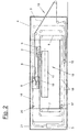
- FIG 2 shows a preferred embodiment of the Fleece layer (4).
- He is a so-called fleece belt layer designed according to WO 97/19209.
- He has two endless and circular laying tapes (6,7), the independently by suitable drives (not shown) are driven.
- the laying tapes (6,7) are over two Main car (8.9) with independent drives (not shown) and arranged there deflection and Guided roles.
- two auxiliary vehicles (16,17) over which the laying tapes (6,7) are also guided by pulleys.
- the Auxiliary carriages (16, 17) are connected via suitable drive belts (18) or other connection means either independently driven or with the associated main car (8,9) connected.
- the auxiliary wagons (16, 17) tighten the Layers (6,7) and allow the two Main car (8.9) deviates from the normal Move the coupling reference against each other.
- Decoupling of the main carriage (8.9) from one another can internal tape and pile storage are formed which Edge thickening of the deposited fleece (10) prevented. This occurs at the reversal points of the lower one Main car or laying car (9) and braking and acceleration areas there Car movement only as much pile (3) as for one uniform pile placement is desired.
- Velocity interventions form a profile of the fleece (10) can be achieved.
- the fleece layer (4) is a so-called co-rotating Casually trained, where the two main cars (8,9) move regularly in the same direction, whereby with normal coupling the lower main carriage (9) twice the distance and twice the speed as that upper main car drives.
- With a parallel layer the two laying tapes (6,7) move between the two main carriages (8.9) directly in one in essential horizontal band section, the pile (3) between the laying tapes (6,7) in a pressing zone is guided and held with slight clamping. additionally can be on the upper main car or superstructure (8) closed belt inlet with another pressure zone to be available.
- the fleece layer (4) can also be used as a so-called opposed layers similar to EP 0 315 930 his.
- the two main carriages (8.9) move counter to each other, with the two laying tapes (6,7) between the main car (8,9) via a stationary Redirection are performed.
- the profile forming device (20) is shown in FIG preferred embodiment part of the fleece layer (4) and affects the speed of the tapes (6,7) and the two separately driven and controllable main car (8.9).
- the Profile formation deliberately differences in speed between the belt speed and the Laying carriage speed at the pile exit point on Laying carriage (9) generated. If the belt circulation speed is higher than the driving speed of the laying carriage (9), more pile emerges, resulting in a corresponding increase the fleece density leads. Conversely, with one Reduction of the belt circulation speed compared to the Laying carriage speed a reduction in Fleece density.
- the drives are controlled (5) the laying tapes (6,7) and the main carriage (8,9) separately set from each other and to any suitable Relative relationships set.
- the Profile forming device (20) in any other be designed in a suitable manner. You can do it for example the constructions and functions according to the EP-A-0 521 973, EP-A-0 371 948, WO 98/37264, EP-A-0 659 220, DE-A-43 04 988, WO 97/19209 and DE-A-38 43 180.
- the fleece layer (4) can take place as a fleece belt layer also as a so-called wagon layer or be designed as a camelback layer.
- the same can the other components of the fleece system (1), in particular the pile generator (2) and the consolidation device (12) in any suitable manner in training and arrangement be modified.
Description
Die Erfindung betrifft ein Vliesanlage und eine Betriebsverfahren mit den Merkmalen im Oberbegriff des Verfahrens- und Vorrichtungshauptanspruchs.The invention relates to a nonwoven system and a Operating method with the features in the preamble of Main procedural and device claim.
Eine solche Vliesanlage ist aus der Praxis bekannt. Sie besteht aus mindestens einem Vliesleger, der einen von einem vorgeschalteten Florerzeuger zugeführten einlagigen Flor in ein mehrlagiges Vlies umfaltet und mindestens einer nachgeordneten Verfestigungseinrichtung zuführt.Such a fleece system is known from practice. she consists of at least one fleece layer, one of single layer fed to an upstream pile generator Folded pile in a multi-layer fleece and at least a downstream consolidation device.
Aus der EP-A-0 315 930 ist es bekannt, den innerhalb der Vliesanlage eingesetzten Vliesleger mit einer Profilbildungseinrichtung auszurüsten, mit der die Dichte des Vlieses über die Legebreite nach Wunsch verändert werden kann. Hierdurch lassen sich unerwünschte Dichteänderungen, die z.B. an der nachfolgenden Verfestigungseinrichtung auftreten können, vorbeugend kompensieren. Für die konkrete Ausgestaltung der Profilbildungseinrichtung lehrt die Entgegenhaltung eine frei programmierbare Steuerung und getrennte und separat steuerbare Antriebe von Hauptwagen und Legebändern. Durch bewusste Erzeugung von Geschwindigkeitsunterschieden am Floraustritt des Legewagens lässt sich die Florablage und damit die Dichte des Vlieses beeinflussen.From EP-A-0 315 930 it is known that the within Fleece system used fleece layer with a Equip profile forming device with which the density of the fleece changed over the laying width as desired can be. This can cause unwanted Changes in density, e.g. on the following Solidification device can occur preventively compensate. For the specific design of the Profile formation facility teaches citation one freely programmable control and separate and separate controllable drives of main car and laying tapes. By deliberate generation of speed differences at The pile tray and thus influencing the density of the fleece.
Vliesleger mit anderen Profilbildungseinrichtungen sind aus der EP-A-0 521 973, EP-A-0 371 948, WO 98/37264, EP 0 659 220, DE-A-43 04 988 und WO 97/19209 bekannt. Die Profilbildung des Vlieses wird hierbei auf unterschiedlichen Wegen erreicht, z.B. durch veränderte Abnahmegeschwindigkeiten des Flors am Florerzeuger, durch Veränderung des Vliesleger-Geschwindigkeitsniveaus gegenüber der Krempel, ggf. unter Einbeziehung eines zwischengeschalteten Speichers, durch unterschiedliche Legebreiten bei der Florablage auf dem Abführband oder dgl..Fleece layers with other profile formation facilities are from EP-A-0 521 973, EP-A-0 371 948, WO 98/37264, EP 0 659 220, DE-A-43 04 988 and WO 97/19209 are known. The Profile formation of the fleece is based on this reached different ways, e.g. through changed Decrease speeds of the pile on the pile generator Change in the fleece layer speed level opposite the clutter, possibly including a intermediate memory, by different Laying widths when laying the flora on the discharge belt or etc. ..
Aus der DE-A-38 43 180 ist es ferner bekannt, Lagenschlussfehler des Vlieslegers zu kompensieren. Hierzu wird die Dichte oder die Masse pro Flächeneinheit des auslaufenden Vlieses gemessen um festzustellen, ob die Vliesbildung gleichmäßig ist und die im Zickzack abgelegten Florbahnen mit ihren Rändern im gewünschten Lagenschluss deckungsgleich übereinander zu liegen kommen. Hierdurch wird ein über die gesamte Legebreite gleichmäßiges Vlies mit einer einheitlichen Dichte oder Dicke erzielt. Dies ist das Gegenteil von einer Profilbildung.From DE-A-38 43 180 it is also known Compensate for the layer closing error of the nonwoven layer. For this the density or mass per unit area of the leaking fleece measured to determine whether the Fleece formation is even and zigzag stored cardboard sheets with their edges in the desired Closing position overlap. This creates a spread over the entire width uniform fleece with a uniform density or Thickness achieved. This is the opposite of one Profiling.
Die JP 03193921A zeigt eine ähnliche Vliesanlage. Sie besteht aus einer Karde, einem ersten Vliesleger, einer nachgeschalteten zweiten Karde, einem weiteren Vliesleger und einer Nadelmaschine. Über Messeinrichtungen wird an verschiedenen Stellen die Dicke bzw. der Durchhang des Flors gemessen. Ferner wird über Messeinrichtungen die Legebreite des vom ersten Vliesleger kommenden Vlieses gemessen, um den korrekten Lagenschluss bei dem vom zweiten Vliesleger gelegten Vlies sicherzustellen. An Hand der Messergebnisse werden die Karde und die Nadelmaschine gesteuert, um die gewünschte Qualität des Endproduktes zu erreichen. Durch die verschiedenen Messeinrichtungen in der Vliesanlage soll sichergestellt werden, dass der Prozess und die Vliesanlage stabil und konstant ablaufen und dass ein kontrollierter Bezug zwischen der Dicke oder Dichte des Endproduktes und der Einstellung der Karde bzw. Nadelmaschine besteht. Hierdurch will man durch Änderungen der Floreinstellungen an der Karde direkten Einfluss auf die gewünschten Ergebnisse am Endprodukt nehmen ohne dass die dazwischen liegenden Prozess- und Anlagenteile hierauf einen verfälschenden Einfluss ausüben können. Eine Profiländerung des Vliese findet in dieser Vliesanlage nicht statt. Die Vliesleger sind von konventioneller Bauart. Die Messeinrichtungen haben außerdem keinen störenden Einfluss auf die Funktion der Vliesleger.JP 03193921A shows a similar fleece system. she consists of a card, a first fleece layer, one downstream second card, another fleece layer and a needle machine. About measuring devices is on different places the thickness or the sag of the Flors measured. Furthermore, the measuring devices Laying width of the fleece coming from the first fleece layer measured to ensure the correct closing of the layers at second fleece layer to ensure laid fleece. Based The carding machine and the needle machine are the results of the measurements controlled to the desired quality of the final product to reach. Through the various measuring devices in the fleece system is to ensure that the Process and the fleece system run stable and constant and that a controlled relationship between the thickness or Density of the end product and the setting of the card or Needle machine exists. You want to make changes the pile settings on the card directly affect take the desired results on the final product without that the process and plant components in between can have a distorting influence. A Profile change of the fleece takes place in this fleece system not instead. The fleece layers are conventional Design type. The measuring devices also have none disruptive influence on the function of the fleece layer.
Es ist Aufgabe der vorliegenden Erfindung, eine solche Vliesanlage zu verbessern.It is an object of the present invention, such To improve the fleece system.
Die Erfindung löst diese Aufgabe mit den Merkmalen im
Verfahrens- und Vorrichtungshauptanspruch.
Bei der erfindungsgemäßen Vliesanlage oder allgemein
Faseranlage ist an einer geeigneten Stelle hinter dem
Auslass des Vlieslegers eine Messeinrichtung zur
Bestimmung der Dichte des Vlieses angeordnet. Die
ermittelten Dichtewerte werden zur Einstellung der
Profilbildungseinrichtung herangezogen, so dass die
gewünschte Profilbildung gezielt eingestellt und überwacht
oder geregelt werden kann. Zur Automatisierung der
Überwachung und Regelung empfiehlt es sich, die
Messeinrichtung mit der Profilbildungseinrichtung in einem
Regekreis zu verbinden und im weiteren vorzugsweise auch
die Messungen kontinuierlich oder zumindest
intermittierend durchzuführen. Dadurch kann die
Profilbildung während des Betriebs laufend überwacht und
bei Auftreten eventueller Fehler nachgeregelt werden.
Die Messeinrichtung ist vorzugsweise hinter der
Verfestigungseinrichtung angeordnet. Sie erfasst hierdurch
eventuelle Dichtefehler im Endprodukt, die in irgendeiner
beliebigen Stelle innerhalb einer kompletten Vliesanlage
verursacht sein können und sich unabhängig von ihrem
Entstehungsort durch eine Nachregelung der Profilbildung
im Vlieslegerbereich kompensieren lassen.The invention solves this problem with the features in the main method and device claim.
In the nonwoven system according to the invention or in general the fiber system, a measuring device for determining the density of the nonwoven is arranged at a suitable location behind the outlet of the nonwoven layer. The density values determined are used to set the profile formation device, so that the desired profile formation can be specifically set and monitored or regulated. To automate the monitoring and control, it is advisable to connect the measuring device to the profile-forming device in a control loop and, furthermore, preferably to carry out the measurements continuously or at least intermittently. This allows the profile formation to be continuously monitored during operation and readjusted if any errors occur. The measuring device is preferably arranged behind the solidification device. In this way, it detects any density errors in the end product, which can be caused anywhere in a complete fleece system and can be compensated for by adjusting the profile formation in the fleece layer area, regardless of where it originates.
Der Vliesleger und die Profilbildungseinrichtung können in beliebig geeigneter Weise ausgebildet sein. In der bevorzugten Ausführungsform wird die Profilbildung durch Erzeugung von Geschwindigkeitsdifferenz zwischen Band- und Wagengeschwindigkeit am Florauslass des Legewagens erzeugt. Diese Ausführung hat Vorteile bei der zielgenauen Steuerung der Profilbildung.The fleece layer and the profile forming device can be in be formed in any suitable manner. In the preferred embodiment is the profile formation by Generation of speed difference between belt and Carriage speed at the pile outlet of the laying carriage generated. This version has advantages in the targeted Control of profile creation.
Die Messeinrichtung kann in beliebig geeigneter Weise ausgebildet sein. Für einen kontinuierlichen Betrieb und eine Online-Regelung empfehlen sich optische oder radiometrische Messeinrichtungen.The measuring device can be used in any suitable manner be trained. For continuous operation and an online regulation is recommended optical or radiometric measuring equipment.
In der Unteransprüchen sind weitere vorteilhafte Ausgestaltungen der Erfindung angegeben. In the subclaims are further advantageous Embodiments of the invention specified.
Die Erfindung ist in den Zeichnungen beispielsweise und schematisch dargestellt. Im einzelnen zeigen:
- Figur 1:
- ein schematisches Anlagenkonzept einer Vliesanlage mit einem Vliesleger und einer Profilbildungseinrichtung nebst Dichtemesseinrichtung mit weiteren vorund nachgeschalteten Anlagenkomponenten und
- Figur 2:
- einen Querschnitt durch einen Vliesleger entsprechend Figur 1.
- Figure 1:
- a schematic system concept of a nonwoven system with a fleece layer and a profile forming device together with density measuring device with further upstream and downstream system components and
- Figure 2:
- 2 shows a cross section through a fleece layer corresponding to FIG. 1.
Figur 1 zeigt in einer Schemadarstellung eine Vliesanlage (1). Diese besteht aus mindestens einem Vliesleger (4) mit einer Messeinrichtung (13) zur direkten oder mittelbaren Ermittlung der Dichte des auslaufenden Vlieses (10). Zur Erweiterung der Vliesanlage (1) kann dem Vliesleger (4) ein Florerzeuger (2), z.B. eine Krempel, vorgeschaltet sein. Der Florerzeuger (2) kann auch eine Einrichtung zur Aufbereitung der Fasern und sonstige geeignete Komponenten aufweisen. Der Florerzeuger (2) erzeugt einen einlagigen Flor (3) aus beliebig geeigneten Fasern, z.B. Kunstfasern oder Naturfasern, und führt diesen über geeignete Fördermittel dem Einlass oder Floreinlauf (15) des Vlieslegers (4) zu.Figure 1 shows a fleece system in a schematic representation (1). This consists of at least one fleece layer (4) a measuring device (13) for direct or indirect Determination of the density of the leaking fleece (10). to Extension of the fleece system (1) can a pile generator (2), e.g. a card, upstream his. The pile generator (2) can also be a device for Preparation of the fibers and other suitable components exhibit. The pile generator (2) creates a single layer Pile (3) of any suitable fibers, e.g. synthetic fibers or natural fibers, and leads them over suitable Funding the inlet or pile inlet (15) of the Fleece layer (4).
Der Vliesleger (4) faltet den zugeführten einlagigen Flor (3) zu einem quer auslaufenden, mehrlagigen Vlies (10) um, das auf einem Abführband (11) abgelegt wird. Die Florlagen werden hierbei im Zickzack auf dem Abführband (11) abgelegt. Das Vlies (10) wird anschließend einer geeigneten Verfestigungseinrichtung (12), z.B. einer Nadelmaschine oder einer Thermofusionseinrichtung, zugeführt, in der das Vlies (10) in geeigneter Weise verfestigt und verdichtet wird. Die Messeinrichtung (13) ist vorzugsweise auslassseitig hinter der Verfestigungseinrichtung (12) angeordnet. Alternativ oder zusätzlich kann eine Messeinrichtung (13) auch zwischen dem Vliesleger (4) und der Verfestigungseinrichtung (12) angeordnet sein.The fleece layer (4) folds the supplied single-ply pile (3) to form a transversely running, multi-layer fleece (10), which is placed on a discharge belt (11). The pile layers are zigzagged on the discharge belt (11) stored. The fleece (10) then becomes one suitable solidification device (12), e.g. one Needle machine or a thermofusion device, supplied in the fleece (10) in a suitable manner is solidified and compacted. The measuring device (13) is preferably on the outlet side behind the Solidification device (12) arranged. Alternatively or in addition, a measuring device (13) can also be used between the fleece layer (4) and the consolidation device (12) be arranged.
Die Vliesanlage (1) kann darüber hinaus noch weitere nicht dargestellte Anlagenkomponenten beinhalten, z.B. eine Streckeinrichtung, einen weiteren Florerzeuger etc., die beispielsweise zwischen dem Vliesleger (4) und der Verfestigungseinrichtung (12) angeordnet sein können. Hinter der Verfestigungseinrichtung (12) beziehungsweise der Messeinrichtung (13) können eine Schneideinrichtung, eine Wickelvorrichtung und sonstige geeignete Anlagenkomponenten angeordnet sein. In Abwandlung des gezeigten Ausführungsbeispieles können außerdem mehrere Vliesleger (4) hintereinander angeordnet sein.The fleece system (1) cannot beyond that included system components, e.g. a Stretching device, another pile generator etc., the for example between the fleece layer (4) and the Solidification device (12) can be arranged. Behind the consolidation device (12) or the measuring device (13) can be a cutting device, a winding device and other suitable Plant components can be arranged. As a variation of the shown embodiment can also several Fleece layer (4) can be arranged one behind the other.
Der Vliesleger (4) besitzt vorzugsweise eine integrierte Profilbildungseinrichtung (20), mit der die Dichte des abgelegten Vlieses (10) beeinflusst und über die Legebreite gezielt verändert werden kann. Die Profilbildungseinrichtung (20) kann aber auch dem Florerzeuger zugeordnet sein. Grundsätzlich kann die Profilbildungseinrichtung (20) in beliebig geeigneter Weise ausgebildet und angeordnet sein. Beispielsweise kann sie entsprechend der EP 0 315 930, der EP 0 371 948, der WO 98/37264, der EP 0 659 220, der DE-P 43 04 988, der WO 97/19209 und der DE-A-38 43 180 ausgeführt und plaziert sein.The fleece layer (4) preferably has an integrated one Profile forming device (20) with which the density of the deposited fleece (10) influenced and over the Laying width can be changed in a targeted manner. The Profile forming device (20) can also Flor producers must be assigned. Basically, the Profile forming device (20) in any suitable Be trained and arranged. For example they correspond to EP 0 315 930, EP 0 371 948, the WO 98/37264, EP 0 659 220, DE-P 43 04 988, WO 97/19209 and DE-A-38 43 180 executed and placed his.
Üblicherweise ist eine möglichst gleichbleibende Dichte des Vlieses über die gesamte Breite gewünscht. Dies betrifft insbesondere das verfestigte und fertig behandelte Endprodukt, das am Ende der kompletten Vliesanlage (1) herauskommt. In anderen Fällen können auch unterschiedliche Dichteverteilung in bestimmter Lage und Größe erwünscht sein. Dies sind die Vorgaben nach denen sich die Einstellung und Regelung der Profilbildungseinrichtung (20) richtet.Usually the density is as constant as possible of the fleece over the entire width. This especially affects the solidified and finished treated end product that at the end of the complete Fleece system (1) comes out. In other cases, too different density distribution in a certain position and Size may be desired. These are the guidelines according to those the setting and regulation of Profiling device (20) aimed.
Über die Messeinrichtung (13) kann die Dichte des Vlieses (10) festgestellt werden. Vorzugsweise erstreckt sich die Messeinrichtung (13) quer über die gesamte Lege- oder Vliesbreite und misst an mehreren Stellen der Legebreite. Hierbei empfiehlt es sich zur Optimierung der Messergebnisse, eine Vielzahl von Messpunkten vorzusehen, die in einer Reihe oder versetzt zueinander angeordnet und mit einer möglichst hohen Dichte positioniert sind.The density of the fleece can be measured using the measuring device (13) (10) can be determined. Preferably, the Measuring device (13) across the entire laying or Fleece width and measures the laying width in several places. It is recommended to optimize the Measurement results, to provide a large number of measurement points, which are arranged in a row or offset from one another and are positioned with the highest possible density.
Die Messeinrichtung (13) misst vorzugsweise kontinuierlich. Sie kann alternativ auch intermittierend arbeiten, wobei die Dichtemessung während des Produktionsbetriebes mehrmals durchgeführt werden.The measuring device (13) preferably measures continuously. Alternatively, it can also be intermittent work, the density measurement during the Production operations are carried out several times.
Die Messergebnisse dienen zur Einstellung der Profilbildungseinrichtung (20). Diese Einstellung kann manuell geschehen, indem die Dichtewerte über die Legebreite von der Messeinrichtung (13) in geeigneter Weise, z.B. optisch an einem Display angezeigt werden. Bei Auftreten von Unregelmäßigkeiten wird die Profilbildungseinrichtung (20) manuell nachgeregelt.The measurement results are used to set the Profile forming device (20). This setting can done manually by moving the density values over the Laying width of the measuring device (13) in a suitable Manner, e.g. be visually shown on a display. at Irregularities will occur Profile formation device (20) readjusted manually.
In der bevorzugten Ausführungsform ist die Messeinrichtung (13) über eine Leitung (14) mit der Profilbildungseinrichtung (20) in einem Regelkreis verbunden. Die Profilbildungseinrichtung (20) kann hierfür eine geeignete frei programmierbare Steuerung (5) aufweisen, die z.B. einen Rechner mit ein oder mehreren Prozessoren, geeigneten Schnittstellen und ein oder mehren Daten- und Programmspeichern beinhaltet. In der Steuerung (5) wird ein Soll-/Ist-Wertvergleich der gelieferten Dichtedaten durchgeführt und in Abhängigkeit vom Ergebnis die Profilbildungseinrichtung (20) entsprechend einer gewünschten Regellogik nachgeregelt. Hierdurch wird die Dichte des Vlieses (10) kontinuierlich oder zumindest intermittierend überwacht und bei Bedarf automatisch nachgeregelt.In the preferred embodiment, the measuring device (13) via a line (14) with the Profile forming device (20) in a control loop connected. The profile forming device (20) can do this a suitable freely programmable control (5) which e.g. a computer with one or more Processors, suitable interfaces and one or more Data and program storage included. In the control (5) a target / actual value comparison of the delivered Density data carried out and depending on the result the profile forming device (20) corresponds to a required control logic. This will make the Density of the fleece (10) continuously or at least intermittently monitored and automatically when required readjusted.
Vorzugsweise erfolgt die Dichtemessung hinter der Verfestigungseinrichtung (12) am verdichteten Vlies (10) und somit am Endprodukt. Hierdurch werden Dichtefehler erfasst, die an irgendeiner Stelle innerhalb der Vliesanlage (1) auftreten können. Sie werden dann unabhängig vom Verursacher über die Profilbildungseinrichtung (20) nachgeregelt und kompensiert. Bei einer Anordnung der Messeinrichtung (13) unmittelbar hinter dem Vliesleger (4) können Dichtefehler erfasst werden, die in und vor dem Vliesleger (4) entstehen. Dichtefehler in der Verfestigungseinrichtung (12) werden hierdurch nicht festgestellt.The density measurement is preferably carried out behind the Solidification device (12) on the compressed fleece (10) and thus on the end product. This will result in density errors recorded at any point within the Fleece system (1) can occur. Then you will regardless of the causer about the Profile formation device (20) readjusted and compensated. When the measuring device (13) is arranged Density errors can occur immediately behind the fleece layer (4) recorded in and in front of the fleece layer (4) arise. Density error in the solidification device (12) are not determined by this.
Eine der Hauptursachen für die genannten Dichtefehler ist die Verfestigungseinrichtung (12). Hierbei kommt es von Haus aus zu einer Erhöhung der Faserdichte im Randbereich des Vlieses (10). Bei der Verfestigung schrumpft das Vlies (10) an den Längsrändern und bildet einen seitlichen Einsprung. Dies führt zu einer höheren Verdichtung in den längs laufenden Randbereichen des Vlieses (10). Diesem Effekt wird über die Profilbildungseinrichtung (20) entgegengewirkt, indem im Innenbereich zwischen diesen Rändern bei der Vliesbildung die Dichte durch verstärkte Florablage und eine damit verbundene vermehrte Faserzuführung erhöht wird. Diese zu kompensierenden randseitigen Verdichtungen treten im wesentlichen bei allen Arten von Verfestigungseinrichtungen (12) ein.One of the main causes of the density errors mentioned is the solidification device (12). Here it comes from House to increase the fiber density in the edge area the fleece (10). The fleece shrinks during consolidation (10) on the longitudinal edges and forms a lateral Entry point. This leads to a higher compression in the longitudinal edge areas of the fleece (10). this Effect is made via the profile forming device (20) counteracted by the interior between these Margins in the formation of nonwovens by increased Flora deposit and an associated increased Fiber feed is increased. To compensate for this edge compressions essentially occur all types of solidification devices (12).
Darüber.hinaus können auch andere Dichtefehler temporär und/oder lokal auftreten. Sie werden z.B. verursacht durch Unregelmäßigkeiten bei der Florerzeugung. Desgleichen können auch innerhalb der Verfestigungseinrichtung (12) durch Abnutzung Unterschiede in der Verfestigung quer über die Legebreite entstehen. Dies ist z.B. der Fall, wenn in der Vliesanlage (1) unterschiedlich breite Vliese (10) gefertigt werden. Hierdurch nutzen sich die innenliegenden Nadeln oder anderen Verfestigungselemente stärker als die randseitigen ab und führen zu einer schlechteren Verdichtung im Innenbereich. Andererseits kommt es auch vor, dass das Vlies (10) nicht immer mittensymmetrisch der Verfestigungseinrichtung (12) zugeführt wird und seitlich nach der einen oder anderen Richtung versetzt sein kann. Dies führt ebenfalls zu einer ungleichmäßigen Abnutzung und entsprechenden Änderungen im Verfestigungs- und Verdichtungsverhalten. Als weitere Ursache kommen auch Toleranzen und Unregelmäßigkeiten bei der Vliesbildung und der Profilbildung als Ursache für Verdichtungsfehler in Betracht. Die tatsächliche Profilbildung weicht dann von den Einstellungen ab. All diese Ursachen können durch die Messeinrichtung (13) in Verbindung mit der Profilbildungseinrichtung (20) kompensiert werden.In addition, other density errors can be temporary and / or occur locally. You will e.g. caused by Irregularities in the pile production. Similarly can also within the solidification device (12) due to wear differences in the hardening across the laying width arise. This is e.g. the case when in the fleece system (1) fleeces of different widths (10) are manufactured. As a result, the inside use Needles or other strengthening elements stronger than that marginal and lead to a worse Compaction indoors. On the other hand, it also happens before that the fleece (10) is not always the center of symmetry Solidification device (12) is supplied and laterally can be offset in one direction or the other. This also leads to uneven wear and corresponding changes in consolidation and Densification behavior. Another cause also come Tolerances and irregularities in the formation of fleece and profile formation as the cause of compaction errors in Consideration. The actual profile formation then deviates the settings. All of these causes can be caused by the Measuring device (13) in connection with the Profile forming device (20) can be compensated.
Die Messeinrichtung (13) kann in beliebig geeigneter Weise konstruktiv ausgebildet sein und als direkte oder indirekte Dichtemessung funktionieren. Für eine Online-Messung empfehlen sich radiometrische Messeinrichtungen, die das Vlies (10) mit einer über die Legebreite im wesentlichen gleichmäßig verteilten Strahlung beaufschlagen und die durch unterschiedliche Dichten hervorgerufenen Strahlungsänderungen registrieren. Unterschiedliche Dichten können beispielsweise zu einem unterschiedlichen Ablenkverhalten und einer unterschiedlichen Streuung der Strahlung führen. Die Strahlung kann von beliebig geeigneter Art sein, z.B. Beta-Strahlung, pulsierende Mikrowellen oder dgl.. Die Dichtemessung in Verbindung mit einer Feuchtigkeitsmessung wird z. B. durch die Literaturstelle Kraszewski, Andrzej W. "Microwave Aquametry-Needs and Prospectives" in IEEE Transactions on Microwave Theory and Techniques, vol. 39, no. 5, Mai 1991 aufzeigt.The measuring device (13) can be used in any suitable manner be constructed constructively and as direct or indirect density measurement work. For one Online measurements are recommended radiometric Measuring devices that the fleece (10) with a Spreading width essentially evenly distributed Expose radiation and that by different Register density-induced radiation changes. Different densities can, for example, lead to one different distraction behavior and one lead to different scattering of the radiation. The Radiation can be of any suitable type, e.g. Beta radiation, pulsating microwaves or the like. The Density measurement in connection with a moisture measurement z. B. by the literature Kraszewski, Andrzej W. "Microwave Aquametry Needs and Prospectives" in IEEE Transactions on Microwave Theory and Techniques, vol. 39, no. 5, May 1991.
Des weiteren kommen auch optische Messeinrichtungen (13) in Betracht. Dies betrifft insbesondere Messsysteme, die mit nach dem Auflicht- oder Durchlichtverfahren mit z.B. einer gegebenenfalls pulsierenden Infrarot-Lichtquelle arbeiten. Diese Dichtemessungen und Messsysteme können z. B. entsprechend der DD-A-260 766, der DE-A-38 16 319, der SU-A-1 295 340, der US-A-4,865,054 oder der EP-A-0 513 013 ausgestaltet sein.Furthermore there are also optical measuring devices (13) into consideration. This applies in particular to measuring systems that with the incident light or transmitted light method with e.g. a possibly pulsating infrared light source work. These density measurements and measuring systems can z. B. according to DD-A-260 766, DE-A-38 16 319, SU-A-1 295 340, US-A-4,865,054 or the EP-A-0 513 013.
In einer weiteren Abwandlung ist es möglich, das Vlies (10) an mehreren Stellen über der Legebreite über Druckmessdosen oder andere geeignete Aufnehmer lokal zu wiegen und hierüber die Dichte zu bestimmen. Eine Dichtemessung kann auch über die Ausübung von Druck oder Kraft auf das Vlies (10) und Messung der Reaktionskraft mittels eines federnden Druckfühlers erfolgen, z.B. entsprechend der EP-A-0 087 611.In a further modification, it is possible to use the fleece (10) in several places above the laying width Pressure load cells or other suitable sensors locally weigh and determine the density. A Density measurement can also be done through the application of pressure or Force on the fleece (10) and measurement of the reaction force by means of a resilient pressure sensor, e.g. according to EP-A-0 087 611.
Figur 2 zeigt eine bevorzugte Ausführungsform des Vlieslegers (4). Er ist als sogenannter Vliesbandleger entsprechend der WO 97/19209 ausgebildet. Er besitzt zwei endlose und im Kreis umlaufende Legebänder (6,7), die eigenständig durch geeignete Antriebe (nicht dargestellt) angetrieben sind. Die Legebänder (6,7) werden über zwei Hauptwagen (8,9) mit eigenständigen Antrieben (nicht dargestellt) und dort angeordnete Umlenk- und Führungsrollen geführt. Außerdem können zwei Hilfswagen (16,17) vorhanden sein, über die die Legebänder (6,7) ebenfalls mittels Umlenkrollen geführt sind. Die Hilfswagen (16,17) sind über geeignete Treibriemen (18) oder andere Verbindungsmittel entweder selbständig angetrieben oder mit dem jeweils zugehörigen Hauptwagen (8,9) verbunden. Die Hilfswagen (16,17) straffen die Legebänder (6,7) und erlauben es, dass die beiden Hauptwagen (8,9) sich abweichend vom normalen Kopplungsbezug gegeneinander bewegen. Durch eine solche Entkoppelung der Hauptwagen (8,9) untereinander kann ein interner Band- und Florspeicher gebildet werden, der Randverdickungen des abgelegten Vlieses (10) verhindert. Hierdurch tritt an den Umkehrpunkten des unteren Hauptwagens beziehungsweise Legewagens (9) und den dortigen Brems- und Beschleunigungsbereichen der Wagenbewegung nur soviel Flor (3) aus, wie für eine gleichmäßige Florablage erwünscht ist. Hierbei kann allerdings auch gezielt durch entsprechende Geschwindigkeitseingriffe eine Profilbildung des Vlieses (10) erreicht werden.Figure 2 shows a preferred embodiment of the Fleece layer (4). He is a so-called fleece belt layer designed according to WO 97/19209. He has two endless and circular laying tapes (6,7), the independently by suitable drives (not shown) are driven. The laying tapes (6,7) are over two Main car (8.9) with independent drives (not shown) and arranged there deflection and Guided roles. In addition, two auxiliary vehicles (16,17) over which the laying tapes (6,7) are also guided by pulleys. The Auxiliary carriages (16, 17) are connected via suitable drive belts (18) or other connection means either independently driven or with the associated main car (8,9) connected. The auxiliary wagons (16, 17) tighten the Layers (6,7) and allow the two Main car (8.9) deviates from the normal Move the coupling reference against each other. By such Decoupling of the main carriage (8.9) from one another can internal tape and pile storage are formed which Edge thickening of the deposited fleece (10) prevented. This occurs at the reversal points of the lower one Main car or laying car (9) and braking and acceleration areas there Car movement only as much pile (3) as for one uniform pile placement is desired. Here can but also specifically by appropriate Velocity interventions form a profile of the fleece (10) can be achieved.
Der Vliesleger (4) ist als ein sogenannter gleichläufiger Leger ausgebildet, bei dem sich die beiden Hauptwagen (8,9) regelmäßig in der gleichen Richtung bewegen, wobei bei normaler Koppelung der untere Hauptwagen (9) die doppelte Strecke und die doppelte Geschwindigkeit wie der obere Hauptwagen fährt. Bei einem gleichläufige Leger bewegen sich die beiden Legebänder (6,7) zwischen den beiden Hauptwagen (8,9) auf direktem Wege in einem im wesentlichen horizontalen Bandabschnitt, wobei der Flor (3) zwischen den Legebändern (6,7) in einer Anpresszone mit leichter Klemmung geführt und gehalten ist. Zusätzlich kann am oberen Hauptwagen oder Oberwagen (8) ein geschlossener Bandeinlauf mit einer weiteren Andruckzone vorhanden sein.The fleece layer (4) is a so-called co-rotating Casually trained, where the two main cars (8,9) move regularly in the same direction, whereby with normal coupling the lower main carriage (9) twice the distance and twice the speed as that upper main car drives. With a parallel layer the two laying tapes (6,7) move between the two main carriages (8.9) directly in one in essential horizontal band section, the pile (3) between the laying tapes (6,7) in a pressing zone is guided and held with slight clamping. additionally can be on the upper main car or superstructure (8) closed belt inlet with another pressure zone to be available.
Alternativ kann der Vliesleger (4) auch als sogenannter gegenläufiger Leger ähnlich der EP 0 315 930 ausgebildet sein. Hierbei bewegen sich die beiden Hauptwagen (8,9) gegenläufig zueinander, wobei die beiden Legebänder (6,7) zwischen den Hauptwagen (8,9) über eine stationäre Umlenkung geführt sind. Alternatively, the fleece layer (4) can also be used as a so-called opposed layers similar to EP 0 315 930 his. Here, the two main carriages (8.9) move counter to each other, with the two laying tapes (6,7) between the main car (8,9) via a stationary Redirection are performed.
Die Profilbildungseinrichtung (20) ist in der gezeigten bevorzugten Ausführungsform Bestandteil des Vlieslegers (4) und beeinflusst die Geschwindigkeit der Legebänder (6,7) und der beiden getrennt hiervon angetriebenen und steuerbaren Hauptwagen (8,9). Hierbei werden zur Profilbildung bewusst Geschwindigkeitsdifferenzen zwischen der Bandumlaufgeschwindigkeit und der Legewagengeschwindigkeit an der Floraustrittsstelle am Legewagen (9) erzeugt. Wenn die Bandumlaufgeschwindigkeit höher als die Fahrgeschwindigkeit des Legewagens (9) ist, tritt mehr Flor aus, was zu einer entsprechenden Erhöhung der Vliesdichte führt. Umgekehrt entsteht bei einer Verringerung der Bandumlaufgeschwindigkeit gegenüber der Legewagengeschwindigkeit eine Verringerung der Vliesdichte. Über die Steuerung (5) werden die Antriebe der Legebänder (6,7) und der Hauptwagen (8,9) getrennt voneinander eingestellt und auf beliebig geeignete Relativbeziehungen eingestellt.The profile forming device (20) is shown in FIG preferred embodiment part of the fleece layer (4) and affects the speed of the tapes (6,7) and the two separately driven and controllable main car (8.9). Here are the Profile formation deliberately differences in speed between the belt speed and the Laying carriage speed at the pile exit point on Laying carriage (9) generated. If the belt circulation speed is higher than the driving speed of the laying carriage (9), more pile emerges, resulting in a corresponding increase the fleece density leads. Conversely, with one Reduction of the belt circulation speed compared to the Laying carriage speed a reduction in Fleece density. The drives are controlled (5) the laying tapes (6,7) and the main carriage (8,9) separately set from each other and to any suitable Relative relationships set.
Abweichend vom gezeigten Ausführungsbeispiel kann die Profilbildungseinrichtung (20) in einer beliebigen anderen geeigneten Art und Weise ausgebildet sein. Sie kann dazu beispielsweise die Konstruktionen und Funktionen gemäß der EP-A-0 521 973, EP-A-0 371 948, WO 98/37264, EP-A- 0 659 220, DE-A-43 04 988, WO 97/19209 und DE-A-38 43 180 haben.Deviating from the embodiment shown, the Profile forming device (20) in any other be designed in a suitable manner. You can do it for example the constructions and functions according to the EP-A-0 521 973, EP-A-0 371 948, WO 98/37264, EP-A-0 659 220, DE-A-43 04 988, WO 97/19209 and DE-A-38 43 180.
Abwandlungen des gezeigten Ausführungsbeispieles sind auch in anderer Weise möglich. Der Vliesleger (4) kann statt als Vliesbandleger auch als sogenannter Wagenleger oder als Camelback-Leger ausgeführt sein. Desgleichen können die anderen Komponenten der Vliesanlage (1), insbesondere der Florerzeuger (2) und die Verfestigungseinrichtung (12) in beliebig geeigneter Weise in Ausbildung und Anordnung abgewandelt werden. Modifications of the embodiment shown are also possible in another way. The fleece layer (4) can take place as a fleece belt layer also as a so-called wagon layer or be designed as a camelback layer. The same can the other components of the fleece system (1), in particular the pile generator (2) and the consolidation device (12) in any suitable manner in training and arrangement be modified.
- 11
- Vliesanlage, FaseranlageFleece plant, fiber plant
- 22
- Florerzeuger, KrempelPile generator, clutter
- 33
- Florpile
- 44
- Vlieslegerlapper
- 55
- Steuerungcontrol
- 66
- Legebandlaying belt
- 77
- Legebandlaying belt
- 88th
- Hauptwagen, OberwagenMain car, superstructure
- 99
- Hauptwagen, LegewagenMain car, laying car
- 1010
- Vliesfleece
- 1111
- AbführbandDischarge Conveyor
- 1212
- Verfestigungseinrichtung, NadelmaschineSolidification device, needle machine
- 1313
- Messeinrichtungmeasuring device
- 1414
- Leitungmanagement
- 1515
- Einlass, FloreinlaufInlet, pile inlet
- 1616
- Hilfswagenauxiliary carriage
- 1717
- Hilfswagenauxiliary carriage
- 1818
- Treibriemenbelts
- 1919
- Auslass, VliesauslaufOutlet, fleece spout
- 2020
- ProfilbildungseinrichtungProfile educational institution
- 2121
- Regelkreisloop
Claims (11)
- Method for operating a non-woven plant, consisting of at least one non-woven plaiter (4) which folds a web (3), supplied by a preceding web producer (2), into a multi-ply non-woven (10), a profile of the non-woven (10) being formed by means of a profile-forming device (20), and the non-woven (10) subsequently being discharged to at least one consolidating device (12), characterized in that, downstream of the outlet (19) of the non-woven plaiter (4), the density of the non-woven (10) is determined by means of a measuring device (13) and the profile-forming device (20) is set according to the measurement values in order to produce the desired non-woven profile.
- Method according to Claim 1, characterized in that the profile-forming device (20) and the production of the non-woven profile are regulated automatically.
- Method according to Claim 1 or 2, characterized in that the density of the non-woven (10) is measured radiometrically, optically, at pressure or via the non-woven weight.
- Non-woven plant, consisting of at least one non-woven plaiter (4) for folding a web (3), supplied by a preceding web producer (2), into a multi-ply non-woven (10), the non-woven plaiter (4) having a profile-forming device (20) for the non-woven (10), and the non-woven (10) subsequently discharging to at least one consolidating device (12), characterized in that, downstream of the outlet (19) of the non-woven plaiter (4), a measuring device (13) is arranged for determining the density of the non-woven (10) and for setting the profile-forming device (20).
- Non-woven plant according to Claim 4, characterized in that the measuring device (13) is connected to the profile-forming device (20) in a control loop (21).
- Non-woven plant according to Claim 4 or 5, characterized in that the measuring device (13) operates continuously or at least intermittently.
- Non-woven plant according to Claim 4, 5 or 6, characterized in that the measuring device (13) is arranged downstream of the consolidating device (12).
- Non-woven plant according to one of Claims 4 to 7, characterized in that the measuring device. (13) is designed as an optical, radiometric or pressure-type measuring device.
- Non-woven plant according to one of Claims 4 to 8, characterized in that the non-woven plaiter (4) has two driven plaiting belts (6, 7) rotating along closed paths and two main carriages (8, 9) controllable and driven separately from these.
- Non-woven plant according to one of Claims 4 to 9, characterized in that the profile-forming device (20) has a freely programmable control (5) for the generation of profile-forming speed differences between the belt speed and the main-carriage speed.
- Non-woven plant according to one of Claims 1 to 10, characterized in that the non-woven plaiter (4) has at least one auxiliary carriage (16, 17) for tensioning at least one plaiting belt (6, 7).
Applications Claiming Priority (2)
| Application Number | Priority Date | Filing Date | Title |
|---|---|---|---|
| DE29909016U DE29909016U1 (en) | 1999-05-26 | 1999-05-26 | Fleece line |
| DE29909016U | 1999-05-26 |
Publications (2)
| Publication Number | Publication Date |
|---|---|
| EP1057906A1 EP1057906A1 (en) | 2000-12-06 |
| EP1057906B1 true EP1057906B1 (en) | 2003-04-23 |
Family
ID=8073850
Family Applications (1)
| Application Number | Title | Priority Date | Filing Date |
|---|---|---|---|
| EP00111172A Expired - Lifetime EP1057906B1 (en) | 1999-05-26 | 2000-05-24 | Web producing installation and method |
Country Status (3)
| Country | Link |
|---|---|
| EP (1) | EP1057906B1 (en) |
| DE (2) | DE29909016U1 (en) |
| ES (1) | ES2197036T3 (en) |
Cited By (3)
| Publication number | Priority date | Publication date | Assignee | Title |
|---|---|---|---|---|
| EP1936016A2 (en) | 2006-12-22 | 2008-06-25 | Asselin-Thibeau | Method for adjusting the local characteristics of a non-woven fabric and corresponding installation |
| EP2014813A1 (en) | 2007-07-09 | 2009-01-14 | Oskar Dilo Maschinenfabrik KG | Method of manufacturing a consolidated nonwoven fabric |
| DE102014111157A1 (en) | 2014-08-06 | 2016-02-11 | TRüTZSCHLER GMBH & CO. KG | Nonwoven system and method for operating the nonwoven system and control unit for this purpose |
Families Citing this family (9)
| Publication number | Priority date | Publication date | Assignee | Title |
|---|---|---|---|---|
| FR2794475B1 (en) | 1999-06-01 | 2001-08-17 | Asselin | METHOD FOR CONTROLLING THE PROFILE OF A NONWOVEN TABLECLOTH AND PRODUCTION FACILITY THEREFOR |
| DE20107004U1 (en) * | 2001-04-23 | 2002-09-05 | Autefa Automation Gmbh | Profile educational institution |
| DE20211365U1 (en) * | 2002-07-27 | 2003-10-09 | Autefa Automation Gmbh | Device for treating fibers |
| DE202004020165U1 (en) * | 2004-12-23 | 2006-05-04 | Autefa Automation Gmbh | lapper |
| ITVI20050096A1 (en) * | 2005-04-04 | 2006-10-05 | Studio Tex Nology Srl | HEAVY DUTY FOR CARDA SAILS AND METHOD OF BLADE OF SUITED VEHICLES MADE WITH THESE FALDATORE |
| EP2545213B1 (en) * | 2010-03-08 | 2015-05-06 | ERKO Trützschler GmbH | Method and device for measuring the weight of an endless flow of web-shaped fiber material |
| DE202014100908U1 (en) | 2014-02-27 | 2015-05-28 | Autefa Solutions Germany Gmbh | carding |
| EP3450603B1 (en) * | 2017-09-01 | 2020-04-29 | Oskar Dilo Maschinenfabrik KG | Method for forming a profiled non-woven fabric |
| FR3081885B1 (en) | 2018-05-31 | 2020-09-11 | Andritz Asselin Thibeau | FIBER TILE FORMATION SYSTEM |
Family Cites Families (8)
| Publication number | Priority date | Publication date | Assignee | Title |
|---|---|---|---|---|
| DE2657603A1 (en) * | 1976-12-18 | 1978-06-22 | Truetzschler & Co | DEVICE FOR MEASURING A FIBER TAPE |
| SE447807B (en) * | 1985-05-08 | 1986-12-15 | Kmw Ab | KIT AND APPARATUS FOR PREPARING A MATERIAL COAT |
| JP2823910B2 (en) * | 1989-12-21 | 1998-11-11 | 日本フエルト株式会社 | Needle felt manufacturing system |
| CH681019A5 (en) * | 1990-07-04 | 1992-12-31 | Zellweger Uster Ag | |
| DE9212215U1 (en) * | 1992-09-10 | 1994-01-13 | Autefa Maschinenfab | Device for producing a nonwoven from fiber material |
| DE4304988C1 (en) * | 1993-02-18 | 1994-04-07 | Autefa Maschinenfab | Wadding prodn. machinery - has mechanism to extend or condense the web of gauze |
| DE29518587U1 (en) * | 1995-11-23 | 1997-04-10 | Autefa Maschinenfab | Fleece layer |
| CA2184836C (en) * | 1996-09-04 | 2000-03-14 | Jung-Fu Chien | Method for producing a variable density, corrugated resin-bonded or thermo-bonded fiberfill and the structure produced thereby |
-
1999
- 1999-05-26 DE DE29909016U patent/DE29909016U1/en not_active Expired - Lifetime
-
2000
- 2000-05-24 EP EP00111172A patent/EP1057906B1/en not_active Expired - Lifetime
- 2000-05-24 DE DE50001834T patent/DE50001834D1/en not_active Expired - Lifetime
- 2000-05-24 ES ES00111172T patent/ES2197036T3/en not_active Expired - Lifetime
Cited By (4)
| Publication number | Priority date | Publication date | Assignee | Title |
|---|---|---|---|---|
| EP1936016A2 (en) | 2006-12-22 | 2008-06-25 | Asselin-Thibeau | Method for adjusting the local characteristics of a non-woven fabric and corresponding installation |
| EP1936016B1 (en) | 2006-12-22 | 2020-10-21 | Andritz Asselin-Thibeau | Method for adjusting the local characteristics of a non-woven fabric and corresponding installation |
| EP2014813A1 (en) | 2007-07-09 | 2009-01-14 | Oskar Dilo Maschinenfabrik KG | Method of manufacturing a consolidated nonwoven fabric |
| DE102014111157A1 (en) | 2014-08-06 | 2016-02-11 | TRüTZSCHLER GMBH & CO. KG | Nonwoven system and method for operating the nonwoven system and control unit for this purpose |
Also Published As
| Publication number | Publication date |
|---|---|
| DE50001834D1 (en) | 2003-05-28 |
| ES2197036T3 (en) | 2004-01-01 |
| EP1057906A1 (en) | 2000-12-06 |
| DE29909016U1 (en) | 2000-10-05 |
Similar Documents
| Publication | Publication Date | Title |
|---|---|---|
| EP2695976B1 (en) | Supply device for delivering opened fibres or flocked fibres to a transport device | |
| EP1057906B1 (en) | Web producing installation and method | |
| EP1285982B1 (en) | Process and apparatus for producing a fibre web | |
| DE4304988C1 (en) | Wadding prodn. machinery - has mechanism to extend or condense the web of gauze | |
| EP2660375B1 (en) | Method and device for adjusting the fibre orientation on roller cards | |
| EP3110997B1 (en) | Carding apparatus and carding method | |
| DE69912537T2 (en) | Device and method for equalizing the supply of textile fibers in the form of a mat to a card | |
| EP3450603B1 (en) | Method for forming a profiled non-woven fabric | |
| EP3066239B1 (en) | Nonwoven laying apparatus, and nonwoven laying method | |
| DE3229402C2 (en) | DEVICE ON A CARD OR CRAWLE FOR FLEECE PRODUCTION | |
| EP1493854B1 (en) | Process and device for producing nonwovens | |
| WO2007016798A1 (en) | Method for plaiting a fibre web control device and textile machine combination | |
| DE3701745A1 (en) | METHOD AND DEVICE FOR THE PRODUCTION OF FIBER FIBERS FROM PLANTS LAYING ABOVE OTHER | |
| DE19527416C2 (en) | Method and device for forming a multi-layer fiber fleece | |
| EP3450604B1 (en) | Method for forming a profiled, solidified nonwoven fabric product | |
| EP0449905B1 (en) | Process for detecting and correcting folding errors during the manufacture of a web of multi-layer non-woven fabric | |
| DE3242539C2 (en) | Method and device for producing a pile or fleece | |
| DE2925397C2 (en) | Device on a card or card to form a split fiber web | |
| EP2169095B1 (en) | Device for laying a fibre web evenly | |
| DE4119877A1 (en) | Combing machine - has automatic controls comprising electronic circuit between comber heads and output at draw-box | |
| EP4168616B1 (en) | Method for the continuous production of nonwoven fabric, and associated nonwoven fabric production apparatus and nonwoven board | |
| EP0677602B1 (en) | Method and apparatus to produce a sliver of fibre material | |
| EP1715093B1 (en) | Method for controlling the lay down of a web during the formation of a fleece and apparatus for making the same. | |
| WO2023104365A1 (en) | System and method for producing a single-layer or multi-layer nonwoven | |
| DE4234354A1 (en) | Mfg. felt of great width with longitudinal fibres - using stable fibre web of comparatively small width, which is transported continuously and deposited into several layers laying on top of each other |
Legal Events
| Date | Code | Title | Description |
|---|---|---|---|
| PUAI | Public reference made under article 153(3) epc to a published international application that has entered the european phase |
Free format text: ORIGINAL CODE: 0009012 |
|
| AK | Designated contracting states |
Kind code of ref document: A1 Designated state(s): BE DE ES FR GB IT |
|
| AX | Request for extension of the european patent |
Free format text: AL;LT;LV;MK;RO;SI |
|
| 17P | Request for examination filed |
Effective date: 20010209 |
|
| AKX | Designation fees paid |
Free format text: BE DE ES FR GB IT |
|
| 17Q | First examination report despatched |
Effective date: 20020326 |
|
| GRAH | Despatch of communication of intention to grant a patent |
Free format text: ORIGINAL CODE: EPIDOS IGRA |
|
| GRAH | Despatch of communication of intention to grant a patent |
Free format text: ORIGINAL CODE: EPIDOS IGRA |
|
| GRAA | (expected) grant |
Free format text: ORIGINAL CODE: 0009210 |
|
| AK | Designated contracting states |
Designated state(s): BE DE ES FR GB IT |
|
| REG | Reference to a national code |
Ref country code: GB Ref legal event code: FG4D Free format text: NOT ENGLISH |
|
| REF | Corresponds to: |
Ref document number: 50001834 Country of ref document: DE Date of ref document: 20030528 Kind code of ref document: P |
|
| GBT | Gb: translation of ep patent filed (gb section 77(6)(a)/1977) |
Effective date: 20030729 |
|
| REG | Reference to a national code |
Ref country code: ES Ref legal event code: FG2A Ref document number: 2197036 Country of ref document: ES Kind code of ref document: T3 |
|
| ET | Fr: translation filed | ||
| PLBE | No opposition filed within time limit |
Free format text: ORIGINAL CODE: 0009261 |
|
| STAA | Information on the status of an ep patent application or granted ep patent |
Free format text: STATUS: NO OPPOSITION FILED WITHIN TIME LIMIT |
|
| 26N | No opposition filed |
Effective date: 20040126 |
|
| PGFP | Annual fee paid to national office [announced via postgrant information from national office to epo] |
Ref country code: ES Payment date: 20100527 Year of fee payment: 11 |
|
| PGFP | Annual fee paid to national office [announced via postgrant information from national office to epo] |
Ref country code: BE Payment date: 20100527 Year of fee payment: 11 |
|
| BERE | Be: lapsed |
Owner name: *AUTEFA AUTOMATION G.M.B.H. Effective date: 20110531 |
|
| PG25 | Lapsed in a contracting state [announced via postgrant information from national office to epo] |
Ref country code: BE Free format text: LAPSE BECAUSE OF NON-PAYMENT OF DUE FEES Effective date: 20110531 |
|
| REG | Reference to a national code |
Ref country code: DE Ref legal event code: R082 Ref document number: 50001834 Country of ref document: DE Representative=s name: ERNICKE & ERNICKE, DE |
|
| REG | Reference to a national code |
Ref country code: DE Ref legal event code: R082 Ref document number: 50001834 Country of ref document: DE Representative=s name: ERNICKE & ERNICKE, DE Effective date: 20120704 Ref country code: DE Ref legal event code: R081 Ref document number: 50001834 Country of ref document: DE Owner name: AUTEFA SOLUTIONS GERMANY GMBH, DE Free format text: FORMER OWNER: AUTEFA AUTOMATION GMBH, 86316 FRIEDBERG, DE Effective date: 20120704 Ref country code: DE Ref legal event code: R082 Ref document number: 50001834 Country of ref document: DE Representative=s name: ERNICKE PATENT- UND RECHTSANWAELTE, DE Effective date: 20120704 |
|
| REG | Reference to a national code |
Ref country code: ES Ref legal event code: FD2A Effective date: 20131029 |
|
| PG25 | Lapsed in a contracting state [announced via postgrant information from national office to epo] |
Ref country code: ES Free format text: LAPSE BECAUSE OF NON-PAYMENT OF DUE FEES Effective date: 20110525 |
|
| PGFP | Annual fee paid to national office [announced via postgrant information from national office to epo] |
Ref country code: GB Payment date: 20150521 Year of fee payment: 16 |
|
| REG | Reference to a national code |
Ref country code: FR Ref legal event code: PLFP Year of fee payment: 17 |
|
| GBPC | Gb: european patent ceased through non-payment of renewal fee |
Effective date: 20160524 |
|
| REG | Reference to a national code |
Ref country code: FR Ref legal event code: PLFP Year of fee payment: 18 |
|
| PG25 | Lapsed in a contracting state [announced via postgrant information from national office to epo] |
Ref country code: GB Free format text: LAPSE BECAUSE OF NON-PAYMENT OF DUE FEES Effective date: 20160524 |
|
| REG | Reference to a national code |
Ref country code: FR Ref legal event code: PLFP Year of fee payment: 19 |
|
| PGFP | Annual fee paid to national office [announced via postgrant information from national office to epo] |
Ref country code: DE Payment date: 20190615 Year of fee payment: 20 Ref country code: IT Payment date: 20190521 Year of fee payment: 20 |
|
| PGFP | Annual fee paid to national office [announced via postgrant information from national office to epo] |
Ref country code: FR Payment date: 20190521 Year of fee payment: 20 |
|
| REG | Reference to a national code |
Ref country code: DE Ref legal event code: R071 Ref document number: 50001834 Country of ref document: DE |