EP1936016B1 - Method for adjusting the local characteristics of a non-woven fabric and corresponding installation - Google Patents
Method for adjusting the local characteristics of a non-woven fabric and corresponding installation Download PDFInfo
- Publication number
- EP1936016B1 EP1936016B1 EP07150195.1A EP07150195A EP1936016B1 EP 1936016 B1 EP1936016 B1 EP 1936016B1 EP 07150195 A EP07150195 A EP 07150195A EP 1936016 B1 EP1936016 B1 EP 1936016B1
- Authority
- EP
- European Patent Office
- Prior art keywords
- web
- orientation
- width
- lap
- fibres
- Prior art date
- Legal status (The legal status is an assumption and is not a legal conclusion. Google has not performed a legal analysis and makes no representation as to the accuracy of the status listed.)
- Revoked
Links
- 238000000034 method Methods 0.000 title claims description 35
- 238000009434 installation Methods 0.000 title claims description 14
- 239000004745 nonwoven fabric Substances 0.000 title claims description 11
- 239000000835 fiber Substances 0.000 claims description 94
- 238000009826 distribution Methods 0.000 claims description 55
- 238000009833 condensation Methods 0.000 claims description 37
- 230000005494 condensation Effects 0.000 claims description 37
- 238000007596 consolidation process Methods 0.000 claims description 29
- 238000001228 spectrum Methods 0.000 claims description 22
- 239000004753 textile Substances 0.000 claims description 16
- 238000004519 manufacturing process Methods 0.000 claims description 13
- 238000009960 carding Methods 0.000 claims description 12
- 238000000151 deposition Methods 0.000 claims description 11
- 230000000694 effects Effects 0.000 claims description 10
- 238000001514 detection method Methods 0.000 claims description 9
- 230000008021 deposition Effects 0.000 claims description 8
- 238000006073 displacement reaction Methods 0.000 claims description 6
- XLYOFNOQVPJJNP-UHFFFAOYSA-N water Substances O XLYOFNOQVPJJNP-UHFFFAOYSA-N 0.000 claims description 6
- 238000011144 upstream manufacturing Methods 0.000 claims description 5
- 239000000126 substance Substances 0.000 claims description 3
- 238000004080 punching Methods 0.000 claims 3
- 238000004458 analytical method Methods 0.000 claims 2
- 238000010191 image analysis Methods 0.000 claims 1
- 230000033001 locomotion Effects 0.000 description 13
- 230000033228 biological regulation Effects 0.000 description 9
- 241000347389 Serranus cabrilla Species 0.000 description 8
- 230000002457 bidirectional effect Effects 0.000 description 7
- 238000012986 modification Methods 0.000 description 5
- 230000004048 modification Effects 0.000 description 5
- 230000007547 defect Effects 0.000 description 3
- 239000004746 geotextile Substances 0.000 description 3
- 238000012360 testing method Methods 0.000 description 3
- 235000021183 entrée Nutrition 0.000 description 2
- 238000011156 evaluation Methods 0.000 description 2
- 230000001747 exhibiting effect Effects 0.000 description 2
- 230000002093 peripheral effect Effects 0.000 description 2
- 238000002360 preparation method Methods 0.000 description 2
- 239000004743 Polypropylene Substances 0.000 description 1
- 241001080024 Telles Species 0.000 description 1
- 240000008042 Zea mays Species 0.000 description 1
- 230000004075 alteration Effects 0.000 description 1
- 230000015572 biosynthetic process Effects 0.000 description 1
- 239000011248 coating agent Substances 0.000 description 1
- 238000000576 coating method Methods 0.000 description 1
- 230000006835 compression Effects 0.000 description 1
- 238000007906 compression Methods 0.000 description 1
- 239000012141 concentrate Substances 0.000 description 1
- 230000001276 controlling effect Effects 0.000 description 1
- 238000005520 cutting process Methods 0.000 description 1
- 230000007423 decrease Effects 0.000 description 1
- 230000003247 decreasing effect Effects 0.000 description 1
- 238000009950 felting Methods 0.000 description 1
- 238000005259 measurement Methods 0.000 description 1
- 238000009828 non-uniform distribution Methods 0.000 description 1
- 238000005457 optimization Methods 0.000 description 1
- -1 polypropylene Polymers 0.000 description 1
- 229920001155 polypropylene Polymers 0.000 description 1
- 238000012545 processing Methods 0.000 description 1
- 230000001105 regulatory effect Effects 0.000 description 1
- 230000003014 reinforcing effect Effects 0.000 description 1
- 230000003763 resistance to breakage Effects 0.000 description 1
- 238000000926 separation method Methods 0.000 description 1
- 238000009827 uniform distribution Methods 0.000 description 1
Images


Classifications
-
- D—TEXTILES; PAPER
- D04—BRAIDING; LACE-MAKING; KNITTING; TRIMMINGS; NON-WOVEN FABRICS
- D04H—MAKING TEXTILE FABRICS, e.g. FROM FIBRES OR FILAMENTARY MATERIAL; FABRICS MADE BY SUCH PROCESSES OR APPARATUS, e.g. FELTS, NON-WOVEN FABRICS; COTTON-WOOL; WADDING ; NON-WOVEN FABRICS FROM STAPLE FIBRES, FILAMENTS OR YARNS, BONDED WITH AT LEAST ONE WEB-LIKE MATERIAL DURING THEIR CONSOLIDATION
- D04H1/00—Non-woven fabrics formed wholly or mainly of staple fibres or like relatively short fibres
- D04H1/70—Non-woven fabrics formed wholly or mainly of staple fibres or like relatively short fibres characterised by the method of forming fleeces or layers, e.g. reorientation of fibres
- D04H1/74—Non-woven fabrics formed wholly or mainly of staple fibres or like relatively short fibres characterised by the method of forming fleeces or layers, e.g. reorientation of fibres the fibres being orientated, e.g. in parallel (anisotropic fleeces)
-
- D—TEXTILES; PAPER
- D01—NATURAL OR MAN-MADE THREADS OR FIBRES; SPINNING
- D01G—PRELIMINARY TREATMENT OF FIBRES, e.g. FOR SPINNING
- D01G23/00—Feeding fibres to machines; Conveying fibres between machines
- D01G23/06—Arrangements in which a machine or apparatus is regulated in response to changes in the volume or weight of fibres fed, e.g. piano motions
-
- D—TEXTILES; PAPER
- D01—NATURAL OR MAN-MADE THREADS OR FIBRES; SPINNING
- D01G—PRELIMINARY TREATMENT OF FIBRES, e.g. FOR SPINNING
- D01G25/00—Lap-forming devices not integral with machines specified above
-
- D—TEXTILES; PAPER
- D04—BRAIDING; LACE-MAKING; KNITTING; TRIMMINGS; NON-WOVEN FABRICS
- D04H—MAKING TEXTILE FABRICS, e.g. FROM FIBRES OR FILAMENTARY MATERIAL; FABRICS MADE BY SUCH PROCESSES OR APPARATUS, e.g. FELTS, NON-WOVEN FABRICS; COTTON-WOOL; WADDING ; NON-WOVEN FABRICS FROM STAPLE FIBRES, FILAMENTS OR YARNS, BONDED WITH AT LEAST ONE WEB-LIKE MATERIAL DURING THEIR CONSOLIDATION
- D04H1/00—Non-woven fabrics formed wholly or mainly of staple fibres or like relatively short fibres
- D04H1/40—Non-woven fabrics formed wholly or mainly of staple fibres or like relatively short fibres from fleeces or layers composed of fibres without existing or potential cohesive properties
- D04H1/44—Non-woven fabrics formed wholly or mainly of staple fibres or like relatively short fibres from fleeces or layers composed of fibres without existing or potential cohesive properties the fleeces or layers being consolidated by mechanical means, e.g. by rolling
- D04H1/46—Non-woven fabrics formed wholly or mainly of staple fibres or like relatively short fibres from fleeces or layers composed of fibres without existing or potential cohesive properties the fleeces or layers being consolidated by mechanical means, e.g. by rolling by needling or like operations to cause entanglement of fibres
- D04H1/48—Non-woven fabrics formed wholly or mainly of staple fibres or like relatively short fibres from fleeces or layers composed of fibres without existing or potential cohesive properties the fleeces or layers being consolidated by mechanical means, e.g. by rolling by needling or like operations to cause entanglement of fibres in combination with at least one other method of consolidation
- D04H1/482—Non-woven fabrics formed wholly or mainly of staple fibres or like relatively short fibres from fleeces or layers composed of fibres without existing or potential cohesive properties the fleeces or layers being consolidated by mechanical means, e.g. by rolling by needling or like operations to cause entanglement of fibres in combination with at least one other method of consolidation in combination with shrinkage
-
- D—TEXTILES; PAPER
- D04—BRAIDING; LACE-MAKING; KNITTING; TRIMMINGS; NON-WOVEN FABRICS
- D04H—MAKING TEXTILE FABRICS, e.g. FROM FIBRES OR FILAMENTARY MATERIAL; FABRICS MADE BY SUCH PROCESSES OR APPARATUS, e.g. FELTS, NON-WOVEN FABRICS; COTTON-WOOL; WADDING ; NON-WOVEN FABRICS FROM STAPLE FIBRES, FILAMENTS OR YARNS, BONDED WITH AT LEAST ONE WEB-LIKE MATERIAL DURING THEIR CONSOLIDATION
- D04H1/00—Non-woven fabrics formed wholly or mainly of staple fibres or like relatively short fibres
- D04H1/40—Non-woven fabrics formed wholly or mainly of staple fibres or like relatively short fibres from fleeces or layers composed of fibres without existing or potential cohesive properties
- D04H1/44—Non-woven fabrics formed wholly or mainly of staple fibres or like relatively short fibres from fleeces or layers composed of fibres without existing or potential cohesive properties the fleeces or layers being consolidated by mechanical means, e.g. by rolling
- D04H1/46—Non-woven fabrics formed wholly or mainly of staple fibres or like relatively short fibres from fleeces or layers composed of fibres without existing or potential cohesive properties the fleeces or layers being consolidated by mechanical means, e.g. by rolling by needling or like operations to cause entanglement of fibres
- D04H1/498—Non-woven fabrics formed wholly or mainly of staple fibres or like relatively short fibres from fleeces or layers composed of fibres without existing or potential cohesive properties the fleeces or layers being consolidated by mechanical means, e.g. by rolling by needling or like operations to cause entanglement of fibres entanglement of layered webs
Definitions
- the present invention relates to a process for producing a nonwoven fabric having locally determined characteristics, in particular in terms of mechanical strength.
- the invention also relates to an installation for implementing this method.
- the web is folded alternately in one direction and the other on an exit belt, thus giving a web composed of overlapping web segments, tilted alternately in one direction and the other relatively to the direction of the web width.
- the folds between successive segments are aligned along the side edges of the web produced.
- the sheet of fibers obtained is generally intended for a subsequent consolidation treatment, for example by needling, by coating, and / or etc. to give the desired nonwoven fabric, endowed with a certain consistency and having a certain number of characteristics of mechanical strength, particularly in tensile strength.
- the patent FR-A-2 234 395 teaches the speed relationships that must be observed in the spreader-lapper to control the surface weight of the web at all points of its width.
- the needling machine consolidates the web by entangling the fibers with one another and interpenetrating the different layers. Planks lined with a large number of needles perpendicular to the plane of the web regularly strike the web of fibers passing through the needling machine. Fibers of the different layers are thus drawn from one layer to the other, and a felting effect follows which gives the web a certain resistance.
- the web undergoes changes in the distribution of fibers. Due to the interpenetration and the entanglement of the fibers, the web is compacted mainly by reducing its thickness. However, it is also observed that the width of the web decreases slightly. In addition, the surface weight of the water table is often affected by the consolidation process, typically being increased at the edges of the web.
- a drawback of these alterations to the web is that the overall quantity of fibers must be increased so that the lightest point of the consolidated web meets the criteria of weight per unit area requested by the purchaser.
- the heaviest areas of the web, i.e. the edges, then correspond to unnecessary consumption of fibers which is not profitable on sale, as well as an unnecessary increase in the total weight of the web with subsequent drawbacks resulting therefrom, for example during handling or implementation.
- the patent EP-B-0 371 948 describes a process intended to precompensate the defects occurring during the subsequent consolidation, in particular the needling, by locally varying the weight of the topping web introduced into the spreader-lapper. This is achieved by automatically adjusting the speed of a card comber relative to the speed of the card drum. The faster the comb turns relative to the drum, the lighter the haze formed by the comb. The lightest areas of the web are those intended to form the edges of the web.
- the patent EP-A-1 036 227 describes a process making it possible to produce a web whose surface weight has a determined profile over the width of the web, again by locally varying the surface weight of the web of lapping introduced into the spreader-lapper. This is obtained by varying at the level of the card a dynamic adjustment influencing the weight of the web, for example by modifying the spacing between the combing device and the carding drum to modify the quantity of fibers taken up by the combing device, or again by “Condensing” the fibers in a variable manner downstream of the comb.
- the dynamic weight adjustment means form part of a control loop comprising means for detecting the surface weight profile of the consolidated sheet.
- the speed of rotation of the card comber is readjusted according to the difference between the result of this detection and a set point.
- the detection detects at the same time the width of the consolidated web and the regulation corrects the length of the stroke of the lapper carriage of the lapper-lapper as a function of the difference between the detected width and a nominal width setpoint, so as to giving the web an actual width as close as possible to the desired nominal width.
- the longitudinal profile of the surface weights of the web is also regulated.
- the consolidated sheet obtained thus has a width and a surface weight that are very uniform and very close to the respective nominal values targeted.
- the EP 1 057 906 B1 describes another method of dynamically adjusting the weight profile of a web.
- tensile strength values measured in particular according to different directions of the nonwoven, for example according to the direction of the width of the nonwoven ("Cross Direction") and in the longitudinal direction of the nonwoven ("Machine Direction").
- the current practice consists in reinforcing the entire web by increasing the quantity of fibers, locally or in general. To satisfy one of these characteristics, it often comes to use more fiber than required by the other characteristic, which goes against an optimization of the amount of fiber consumed.
- the MD / CD ratio should be as close as possible to the value 1: 1
- the MD / CD ratio has a fairly different value on the edges of the web compared to the central part. Even if the surface weight of the nonwoven is uniform over its entire width, thanks in particular to the weight compensations carried out according to the prior art, the MD / CD ratio of a nonwoven according to the prior art is generally not uniform, because the orientation distribution of the fibers is not the same at all points of the width of the nonwoven. For example, consolidation by needling tends to favor the transverse orientation of the fibers near the center of the web rather than near the edges of the web.
- the web will have to be reinforced over its entire width so that the lowest value is sufficient.
- the invention also seeks to optimize the quantity of fibers necessary to obtain a nonwoven fabric of which all the parts have certain minimum characteristics, as well as to optimize the weight or the volume of such a nonwoven fabric.
- the invention provides a method for manufacturing nonwoven web textiles according to claim 1.
- the distribution of orientation of the fibers is influenced in a targeted manner as a function of the position of said fibers in the direction of the width of the strip.
- dynamic adjustment is meant an adjustment which is revised and if necessary modified continuously or repetitively (for example at regular time intervals) while the installation is operating in production.
- the invention is based on the idea of differentiating the orientations of fibers as a function of the location of the fibers along the width of the web, either to obtain different mechanical characteristics in different areas of the width of the web, or to precompensate for uniformity defects introduced into the mechanical characteristics of the web during subsequent steps of the manufacturing process, in particular during consolidation and more particularly during needling.
- the invention can be used to give the fibers close to the edges of the web before needling a distribution of orientations favoring more the transverse orientation than for the fibers forming the central zone of the web.
- the desired control may aim to provide one or more zones of lower resistance, or a sufficiently low resistance at all points of the textile.
- the notion of “distribution of orientations” is used. This notion takes into account the different orientations present in a given zone, and the greater or lesser abundance of each orientation in this zone.
- the fibers are typically all parallel to the length of the web (orientation distribution curve flattened to give a single segment).
- the initially longitudinal fibers of the non-condensed web have been folded back on themselves and / or “transversalized” by the condensation so that the orientation distribution is no longer unidirectional but omnidirectional, represented by an oval.
- the orientation of the fibers in the web is influenced.
- Such a dynamic adjustment relating to the web is carried out before folding the web back on itself to form the web.
- the orientation distribution of the fibers is adjusted in the successive zones of the length of the web as a function of the position that these zones will take along the width of the web.
- the orientation of the fibers can be influenced by means of adjustable condensation of the web.
- Such condensation of the veil can itself be obtained in several ways which can be used as desired or even be combined with one another.
- the dynamically adjustable condensation according to the invention is obtained at least in part by varying the speeds of at least two rotary members of the card which contribute to the manufacture or transport of the web with respect to each other.
- the condensation is obtained at least in part by adjusting a movement of at least one carriage of the spreader-lapper in a direction substantially transverse to the tablecloth, for example by giving this carriage a speed different from that which would ensure that the web leaves the lapper carriage with a travel speed equal to the displacement speed of the lapper carriage.
- the displacement of the lapper carriage is slower than the movement of the web through the lapper carriage, the web condenses locally at the outlet of the lapper carriage.
- the web is stretched at the exit of the lapper carriage. This can for example locally reduce the effect of a pre-existing condensation of the web and thus modify the local distribution of the orientations of the fibers to make it closer to a longitudinal unidirectional distribution relative to the web.
- the speed of movement of the lapper carriage is equal to the travel speed of the web through the lapper carriage, the web is deposited substantially unchanged on the output apron of the spreader. lapper.
- the relationship between the deposit of the web on the output apron of the spreader-lapper and the travel speed of the output apron conveying the web in formation towards the output of the spreader lapper in a second embodiment, possibly combinable with the first embodiment, the relationship between the deposit of the web on the output apron of the spreader-lapper and the travel speed of the output apron conveying the web in formation towards the output of the spreader lapper.
- the direction in which the web is deposited on the web is thus modified, that is to say the angle formed by this direction with the axes of the web, and therefore the angle formed by the fibers deposited with the axes of the web. sheet, in particular when the fibers of the web are longitudinal relative to the web.
- the angle of inclination of the web segments in the web depends on the ratio between the speed of the outlet apron and the speed of movement of the lapper carriage.
- the fibers of the web are deposited with a less inclination with respect to the width of the web in the vicinity of the edges of the web; which precompensates the defect introduced later by a consolidation process by needling.
- the invention is very advantageously combined with the methods known per se to achieve a predetermined distribution of surface weights over the width of the web.
- the degree of condensation of the parts of the web intended to be located at the edge of the web can be reduced so that the fibers are “more transverse” in the web in the vicinity of the edges of the web before consolidation.
- this results in a variation in surface weight in the vicinity of the edges of the sheet.
- a second variation is added to this first variation which has substantially no effect on the orientation distribution of the fibers, for example a variation in the spacing between the comb and the card drum, or again a variation in the speed of the comb and a proportional variation of the fiber transport members located downstream of the comb.
- an accumulator means capable of absorbing the speed fluctuations is provided downstream of the scraper so that the speed of transport of the fibers downstream of the accumulator is not affected by these fluctuations.
- Such an accumulator may for example be constituted by an apparatus interposed between the card and the spreader, or alternatively by an accumulator placed at the outlet of the spreader lapper, or alternatively by the accumulator carriage of the spreader-lapper as described in EP-A-1 036 227 .
- the method according to the invention comprises a regulation of the dynamic adjustment of the orientation of the fibers as a function of a detection of at least one quantity representative of the orientation distribution of the fibers in the nonwoven, preferably the non-woven after consolidation.
- the measured quantity may be the shrinkage undergone by the web during its consolidation by needling.
- a shrinkage can be interpreted in terms of modification of the orientation distribution of the fibers in the edge zones of the web.
- the dynamic adjustment consists in pre-compensating for this modification by one of the orientation means described above, namely the condensation in the card, between the card and the spreader, or at the exit of the lapper carriage, or else the adjustment of the speed of the spreader output apron relative to the speed of movement of the lapper carriage.
- the measured quantity can be taken from an image of the web which is analyzed to determine the local distribution of orientations, or a numerical value or a set of numerical values which represents this distribution, for example its bidirectional spectrum such as it will be defined later.
- the invention relates to an installation for the production of nonwovens according to claim 20.
- This comprises a card providing at least one web of fibers, a spreader-lapper arranging the web in successive transverse segments on an output apron to form a web, and a consolidation machine such as a needling machine or a binding device. by water, thermal or chemical jet downstream of the outlet apron, characterized in that it further comprises orientation means for influencing the orientation distribution of the fibers according to their position along the width of the web, in a process according to one of claims 1 to 19.
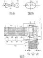
- the consolidation gives a nonwoven fabric having a profile 440a whose edges are significantly heavier, for example example with a surface weight of the order of 115 to 120 for the edges if the surface weight at the center is 100. This increase in the surface weight near the edges is fed by a lateral shrinkage dc of the consolidated sheet with respect to the sheet non-consolidated.
- compensation for variations in surface weight is typically obtained by depositing more fibers in the central part of the web.
- a domed profile 430b is thus produced as shown in dotted lines in figure 1b . Consolidation then gives a nonwoven fabric exhibiting a substantially uniform weight profile 440b.
- the different tensile strengths obtained in the transverse direction CD and in the longitudinal direction MD exhibit a certain heterogeneity between the edges and the central part of the consolidated sheet of the prior art.
- the MD / CD ratio between these two breaking strengths can in some cases be 40% greater near the edges than in the central part.
- the tensile strength in the longitudinal direction of the web (MD strength) is higher near the edges of the web than in its central region, compared to the tensile strength in the width direction of the web (resistance CD). It is believed that this heterogeneity is due to the fact that the orientation of fibers near the edge of the web is altered by the needling process, together with the occurrence of dc shrinkage. According to this theory, the fibers of the edge of the consolidated web would tend to form, on average, a greater angle with the width of the web, than the fibers of the central region of the web.
- Tablecloth 430 ( figure 2 ) is typically obtained by superimposing several segments of S430 sails overlapping each other. The segments are interconnected by folds extending along the edges of the web. The fibers of the web 430 have different orientations resulting from the orientation of the fibers within each of these segments, as well as from the angle A430 according to which these segments are deposited on the mobile apron carrying the web.
- a web made of non-condensed web the fibers of which are therefore longitudinal in the web, exhibits a much greater tensile strength in the transverse direction of the web (CD) than in its longitudinal direction (MD) because the longitudinal direction of the web, and therefore the direction of the fibers, are almost transverse in the water table.
- the orientation distribution in the web is more homogeneous, but the transverse or quasi-transverse orientations remain preferred. Therefore, the resistance CD remains higher than the resistance MD, although the ratio between the two is less than 1: 1 than when the web used is not condensed.
- the distribution of the orientation of all the fibers present can be represented by a closed curve C F linked to this zone and having a center of symmetry Cs.
- the figure 3a represents an example of curve C F for a sheet made of non-condensed veil and the figure 3b an example of curve C F for a sheet made of condensed veil.
- Each point P of the curves C F indicates by its distance from the center Cs the proportion of fibers having an orientation identical to that of the vector ray CsP connecting the center Cs to this point P.
- the orientation of the fibers in the web 430 has been influenced so as to obtain in the central part of the web not yet consolidated an orientation spectrum ON2 different from the orientation spectrum ON1 in the parts of the web close to its edges.
- the orientation of the fibers in a given part of the web 430 is influenced by a dynamic adjustment made upstream of the consolidation treatment in the needling machine 3. More particularly, in this example, the adjustment affects each region of the length of the web. depending on the position that this region of the length of the web will take in the web.
- the fibers of the regions of the web intended to come to be placed at the edges of the web are given an orientation spectrum having a greater longitudinal preponderance (relative to the web) than the fibers of the web intended to come to be placed in the central region of the web. the tablecloth.
- the figure 4 illustrates a nonwoven production installation comprising a card 1 producing a web 421 feeding a spreader-lapper 2.
- the card comprises a feed roller 11 collecting fibers 411 directly or indirectly in a reserve, to feed a card drum 12.
- the periphery of the drum 12 is equipped with known means, not shown, for working the fibers carried by the drum. These fibers are taken from the drum 12 by a combing roller 13, then transferred successively to a first condensing roll 14 and a second condensing roll 15.
- the web 421 thus formed is detached by a stripping roller 16 rotating in the same direction as the last. condenser roller and depositing the web on a conveyor belt 17 leading to the inlet 20 of the spreader-lapper 2.
- the fibers are oriented circumferentially on the comb 13.
- the condensers 14 and 15 are used to increase the surface weight of the veil, reduce the speed of the veil and give the fibers a more varied orientation than on the comb.
- the condensation effect is obtained by giving the second condensation roller 15 a peripheral speed less than that of the first condensation roller 14, the peripheral speed of which is itself lower than that of the comb 13.
- the spreader-lapper 2 comprises an inlet mat or front mat 24 and a rear mat 25 each forming a closed loop. These loops are exterior to each other and bypass various rollers rotating around fixed axes, as well as rollers carried by an accumulator carriage 21 and others carried by a lapper carriage 22. Each of the two belts 24 and 25 is driven by one of the fixed-axis rollers which is associated with it and which is coupled to a respective electric servo motor.
- the web 421 is brought to the accumulator carriage 21 by the inlet belt or front belt 24, one region of which may constitute the transport belt 17, as shown.
- the web passes downward through the first accumulator carriage 21, then the lapper carriage 22.
- the lapper carriage 22 is in reciprocating motion M22 in a direction perpendicular to the width of the web, and thus deposits the web 421 in successive segments on an apron of outlet 28 movable in a direction parallel to the width of the web.
- the successive accumulated and offset segments formed by the web 421 deposited on the outlet apron 28 form the web 431 ( Fig 5 ) which is routed to consolidation processing 3 ( figure 2 ).
- the accumulator carriage 21 is in reciprocating motion M21 in the same direction as the lapper carriage 22 with a displacement law calculated to adjust the distance to be traveled by the web between the inlet 20 of the lapper-lapper and the lapper carriage 22. Said distance is more particularly adjusted to combine with each other the speed of entry of the web 421 into the spreader-lapper with the speed at which the web passes through the lapper carriage 22.
- the entry speed 20 is equal. at the production speed of the card, as modified if necessary at each instant by the comb 13 which can be at variable speed and by the variable condensation which will be described.
- the speed at which the web passes through the lapper carriage 22 is either equal to the travel speed of the lapper carriage 22 if the web is to be deposited without adding condensation or stretching, or is different if the web is to be condensed or stretched when it is deposited on the output apron of the spreader-lapper.
- the dynamic adjustment according to the invention affects the preparation or transport of the web 421, that is to say upstream of the deposition of the web on the outlet apron 28 by the lapper carriage 22.
- this adjustment modification produces in the web 421 entering the spreader-lapper 2 an alternating structure having, along the longitudinal direction of the web 421, an alternation of VC and VB zones which differ in their fiber orientation distributions.
- the areas VB are intended to compose the edge areas B1 of the web 431, while the areas VC are intended to compose its central part.
- the fibers of the web In the VB zones corresponding to the edges of the web, the fibers of the web have a certain OVB orientation spectrum, while in the VC zones corresponding to the center of the web, the fibers of the web have another OVC orientation spectrum.
- the dynamic adjustment is made so as to increase the transverse component of the OVC orientation spectrum of the VC zones of the web 421.
- These VC zones produce then in the sheet a central zone where the fibers present an orientation spectrum ON2 ( figure 2 ) having a larger longitudinal component FM2.
- this same central zone presents an increased MD / CD ratio.
- the MD / CD ratio of the edge zones of the consolidated sheet has been increased by the effect of the needling described with reference to the figure 1c , the two MD / CD ratios can be made equal.
- the method according to the invention can be used to produce other types of distribution profile of the orientation spectra of the fibers within the width of the web such as 431.
- the invention thus makes it possible to produce a nonwoven having, after consolidation, mechanical strengths distributed according to a chosen profile, preferably taking into account the variations directly induced by the consolidation in the edge areas as shown in figure 1c .
- Such selected profiles can make it possible, for example, to produce a textile which will tear more easily along a selected longitudinal zone, for example to facilitate separation or cutting in such a zone.
- the orientation profile of the fibers in the web 431 such as that shown in figure 5 which is symmetrical with respect to the longitudinal axis of the web 431
- the periodicity of variation of the settings influencing the orientation of the fibers corresponds to a half-period of work of the spreader-lapper 2, corresponding to a sequence of a VC zone and a zone VB on the web 421.
- the adjustment variation period corresponds to a complete working period of the spreader-lapper.
- the orientation of the fibers of the web 421 is influenced by carrying out condensation in the VC parts of the web.
- a condensation of the order of 17% by surface weight can cause the value of MD / CD in the consolidated web to vary by approximately 40%, in the case of a geotextile based on polypropylene fibers.
- variable condensation is carried out within the card, during the production or transport of the web, by varying the speeds of at least two rotary members of the card with respect to each other or transportation.
- One of these members rotates for example at a given speed and one or more subsequent members rotate at a lower speed when the condensation is to be effective.
- the web produced will exhibit a condensation of 30%.
- This condensation could for example be carried out in several intermediate phases, with the first condenser roll 14 rotating at 80 m / min and the second condenser roll 15 rotating at 50 m / min.
- the card could include a single condenser roll. Such a condensation of 30% can then be obtained with a comb roller rotating at 130 m / min, the condenser roller rotating at 80 m / min, and the stripper rotating at 100 m / min.
- a comb roller 13 is directly followed by a stripper roller 16. Such a condensation of 30% can then be carried out directly between the comber rotating at 130 m / min and the stripper rotating at 100 m / min.
- a condensation can also be dynamically adjusted on the transport path or within the spreader-lapper 2.
- the transport path can thus include one or more condensing devices. It may be, for example, one or more condenser rolls, the circumferential speed of which is dynamically adjusted.
- Dynamically adjustable condensation can be achieved with a stretching or compression device as described in WO 02/101130 A1 where the FR-A3-2 828 696 placed between the card itself and the spreader-lapper itself. These devices can for example, according to the invention, operate in variable stretching to cancel at least in part, and in a variable manner, a constant condensation at the exit of the card. Both an adjustment of the surface weight and an adjustment of the orientation spectrum are thus carried out, since the zones of the length of the web undergoing the strongest stretching, intended to be placed near the edges of the web, are at the same time.
- a dynamic adjustment of the condensation of the web can also be carried out in the spreader-lapper 2, for example by modifying the law of displacement of one or two of its carriages 21 and 22 so as to adjust the speed at which the web passes through the web.
- lapper carriage 22 relative to the speed of movement of the lapper carriage 22.
- zones for example the two edge zones and the central zone.
- a second embodiment which will be described with reference to figures 7 and 8 , can be implemented as an alternative to the first embodiment or in combination with it.
- a dynamic adjustment is carried out affecting the preparation or transport of the web 432, that is to say at the stage or downstream of the deposition of the web 422 on the outlet apron 28 in the spreader-lapper. 2.
- this adjustment modification produces a modification of the web deposition pattern to form each of the transverse segments making up the web 432, by modifying the inclination of the segment relative to the width of the web.
- the longitudinal direction DB or DC of each segment forms with the width of the web an angle AB or AC respectively.
- the exit apron such as 28 advances at a constant speed.
- the ratio between this constant speed and the speed of movement of the lapper carriage such as 22 defines the angle between the width of the web and the longitudinal direction of the web segments.
- the exit apron is further slowed down, so that the angle AB in the edge areas B2 is less than the angle AC in the central region of the web, as shown. figure 7 .
- the orientation spectrum ON2 at the center of the web is less elongated in the direction of the width of the web than the ON1 orientation spectrum in the edge zones.
- the edge zones After consolidation, the edge zones have an MD / CD ratio close to that of the central zone.
- this second embodiment can also be used to obtain a selected non-uniform profile, with regard to the distribution of resistances within the textile obtained, and not simply a uniform profile.
- the installation according to the invention combines the means described so far aimed at controlling the orientation distributions of the fibers over the width of the web, with means such as according to EP-1 036 227 to control the profile of the surface weights over the width of the web.
- a second dynamic adjustment is carried out affecting the surface weight of the web but having substantially no effect on the orientation of the fibers.
- the second adjustment may be an adjustment varying the quantity of fibers taken by the comber from the carding drum.
- the second adjustment can for example consist in varying the speed of rotation of the comb (the faster the comb turns the less fibers it collects at each turn, and the lighter the haze it produces) or the spacing of the comber relative to the carding drum (the farther away the comber is from the drum, the less fibers it withdraws at each turn, and the lighter the haze it produces).
- the speed of the comber is dynamically adjusted to produce a web whose weight is non-uniform along its longitudinal direction as for example described in EP-A-1036 227 , and the orientation distribution of the fibers in the web is adjusted by dynamically varying the rate of condensation of this web, that is to say for example the ratio between the speed of a detacher and the speed of the comber. Therefore, if at any point in time the speed of the comb is changing and the rate of condensation is to remain constant, typically the speed of the stripper should vary in the same proportion as the speed of the comb.
- this regulation is combined with a regulation of the surface weight profile such as according to the WO A 00/73547 where the EP 1 057 906 B1 .
- a transverse detector 41 of the type of that described in section 3 is placed above the web exiting the needling machine 3.
- WO A 00/73547 comprising a series of sensors aligned parallel to the width of the web or, as a variant, a single so-called "traveling" sensor making back and forth movements above the web.
- the transverse detector 41 detects the width of the consolidated web 440 and the surface weight at different points of the width of the web.
- the detection of the width of the web allows a computer 42 to calculate the lateral shrinkage dc undergone by the web during consolidation, either by difference with a detection of width (not shown) upstream of the needling machine 3, either by difference with the stroke length of the lapper carriage of the lapper-lapper 2.
- This stroke length is known to the computer 42 because the lapper carriage is actuated precisely by a servo-motor (not shown) also controlled by this calculator.
- the width of the edge zone of the sheet which is altered in connection with the phenomenon of shrinkage dc is known from experience or from prior tests. A simple arithmetic calculation and / or preliminary tests make it possible to evaluate the impact of this shrinkage on the orientation distribution of the fibers in the edge zone affected by the shrinkage. As a function of this evaluation, the computer 42 controls an adjustment of the orientation means.
- the computer 42 calculates a rate of condensation which must be applied to the parts of the web intended to form the central zone of the sheet so that this central zone presents in the consolidated sheet an orientation distribution. , or in any case a bidirectional orientation spectrum, which is substantially equal to that of the edge zones.
- the computer 42 receives from the detector 41 measurements of the surface weight at different points of the width of the consolidated sheet 440 and regulates the surface weight profile of the consolidated sheet and the width of the consolidated sheet as described in WO A 00/73547 , by influencing parameters, such as those described previously (speed of the comb, distance of the comb), little or no affecting the orientation of the fibers in the web.
- the figure 4 schematically illustrates the computer 42 sending orders 43 to the condensers 14, 15 and to the detacher 16 for the dynamic adjustment of the condensation, orders 44 to the comb 13 for the dynamic adjustment of the weight without affecting the orientation of the fibers, and orders 46 to the lapper spreader 2 to adjust and define at any time the position of the two lapper carriages 21, 22 in their reciprocating movements M21, M22 as well as the speed of circulation of the belts 24, 25.
- the lines 43, 44, 46 are bidirectional for transmitting in return, to the computer 42, information on the real values of the operating parameters of the card and of the spreader-lapper in particular.
- the regulation it is envisaged to use at the output of the needling machine 3, in addition to the detector 41, at least one image sensor (not shown) in one of the edge zones , and preferably at least three image sensors for the two edge zones and the central zone respectively.
- the images produced by these sensors are analyzed to determine the orientation distribution of the fibers in the images obtained.
- the computer 42 calculates, for example, the bidirectional orientation spectra corresponding to the observed distributions, and controls the orientation means in a direction tending to equalize or keep these bidirectional spectra equal.
- the regulation based on a detection of the transverse shrinkage of the web could be carried out without being combined with a regulation of the surface weight profile.
- the orientation means controlled within the framework of the regulation of the distributions or orientation spectra can be any of those described, for example the drive motor of the output apron of the spreader-lapper 2 as described in reference to figure 7 .
Description
La présente invention concerne un procédé pour produire un textile non-tissé présentant localement des caractéristiques déterminées, en particulier en termes de résistance mécanique. L'invention concerne également une installation pour la mise en œuvre de ce procédé.The present invention relates to a process for producing a nonwoven fabric having locally determined characteristics, in particular in terms of mechanical strength. The invention also relates to an installation for implementing this method.
Il est connu de produire une nappe continue dans un étaleur-nappeur alimenté avec un ou plusieurs voiles de nappage produit(s) dans une carde.It is known to produce a continuous web in a spreader-lapper supplied with one or more webs of topping produced in a card.
Dans l'étaleur-nappeur, le voile est plié alternativement dans un sens et dans l'autre sur un tapis de sortie, donnant ainsi une nappe composée de segments de voile qui se chevauchent, inclinés alternativement dans un sens et dans l'autre relativement à la direction de la largeur de la nappe. Les plis entre segments successifs sont alignés le long des bords latéraux de la nappe produite. La nappe de fibres obtenue est en général destinée à un traitement ultérieur de consolidation par exemple par aiguilletage, par enduction, et/ou etc pour donner le textile non-tissé recherché, doté d'une certaine cohérence et présentant un certain nombre de caractéristiques de résistance mécanique, notamment en résistance à la traction.In the spreader-lapper, the web is folded alternately in one direction and the other on an exit belt, thus giving a web composed of overlapping web segments, tilted alternately in one direction and the other relatively to the direction of the web width. The folds between successive segments are aligned along the side edges of the web produced. The sheet of fibers obtained is generally intended for a subsequent consolidation treatment, for example by needling, by coating, and / or etc. to give the desired nonwoven fabric, endowed with a certain consistency and having a certain number of characteristics of mechanical strength, particularly in tensile strength.
Le brevet
L'aiguilleteuse réalise la consolidation de la nappe par enchevêtrement des fibres entre elles et interpénétration des différentes couches. Des planches garnies de très nombreuses aiguilles perpendiculaires au plan de la nappe frappent régulièrement la nappe de fibres passant par l'aiguilleteuse. Des fibres des différentes couches sont ainsi entraînées d'une couche à l'autre, et il s'ensuit un effet de feutrage qui donne à la nappe une certaine résistance.The needling machine consolidates the web by entangling the fibers with one another and interpenetrating the different layers. Planks lined with a large number of needles perpendicular to the plane of the web regularly strike the web of fibers passing through the needling machine. Fibers of the different layers are thus drawn from one layer to the other, and a felting effect follows which gives the web a certain resistance.
Lors de sa consolidation, la nappe subit des changements dans la répartition des fibres. Du fait de l'interpénétration et de l'enchevêtrement des fibres la nappe est compactée principalement par diminution de son épaisseur. Cependant on observe aussi que la largeur de la nappe diminue légèrement. De plus, le poids surfacique de la nappe est souvent affecté par le processus de consolidation, en étant typiquement accru sur les bords de la nappe.During its consolidation, the web undergoes changes in the distribution of fibers. Due to the interpenetration and the entanglement of the fibers, the web is compacted mainly by reducing its thickness. However, it is also observed that the width of the web decreases slightly. In addition, the surface weight of the water table is often affected by the consolidation process, typically being increased at the edges of the web.
Un inconvénient de ces altérations de la nappe est qu'il faut augmenter la quantité globale de fibres pour que le point le plus léger de la nappe consolidée satisfasse aux critères de poids surfacique demandés par l'acheteur. Les zones les plus lourdes de la nappe, c'est à dire les bords, correspondent alors à une consommation inutile de fibres qui n'est pas rentabilisée à la vente, ainsi qu'à une augmentation inutile du poids total de la nappe avec les inconvénients ultérieurs qui en découlent, par exemple lors de la manutention ou de la mise en œuvre.A drawback of these alterations to the web is that the overall quantity of fibers must be increased so that the lightest point of the consolidated web meets the criteria of weight per unit area requested by the purchaser. The heaviest areas of the web, i.e. the edges, then correspond to unnecessary consumption of fibers which is not profitable on sale, as well as an unnecessary increase in the total weight of the web with subsequent drawbacks resulting therefrom, for example during handling or implementation.
Jusqu'à présent, on a cherché à pallier cet inconvénient en réalisant une nappe présentant avant l'aiguilletage un poids surfacique plus grand en son centre que sur ses bords.Up to now, attempts have been made to overcome this drawback by producing a web having, before needling, a greater surface weight at its center than at its edges.
Ainsi, le brevet
Le brevet
Selon le
Or de plus en plus, les acheteurs tiennent compte de certains critères notamment des valeurs de résistance à la traction, mesurées notamment selon différentes directions du non-tissé, par exemple selon la direction de la largeur du non-tissé ("Cross Direction") et selon la direction longitudinale du non-tissé ("Machine Direction").However, more and more, buyers take into account certain criteria, in particular tensile strength values, measured in particular according to different directions of the nonwoven, for example according to the direction of the width of the nonwoven ("Cross Direction") and in the longitudinal direction of the nonwoven ("Machine Direction").
Par exemple, un critère couramment exigé pour les non-tissés, en particulier dans le domaine des géotextiles, est exprimé sous la forme des grandeurs suivantes:
- la résistance à la rupture en traction dans le sens longitudinal du textile (ou de la nappe), qualifiée de "Machine Direction";
- la résistance à la rupture en traction dans le sens de la largeur du textile (ou de la nappe), qualifiée de "Cross Direction";
- le rapport entre ces deux valeurs de résistance, noté MD/CD, c'est à dire la résistance "Machine Direction" divisée par la résistance "Cross Direction".
- the tensile strength in the longitudinal direction of the textile (or of the web), referred to as "Machine Direction";
- the tensile strength in the direction of the width of the textile (or of the web), referred to as "Cross Direction";
- the ratio between these two resistance values, denoted MD / CD, ie the "Machine Direction" resistance divided by the "Cross Direction" resistance.
Lorsque les caractéristiques mécaniques obtenues dans la nappe consolidée ne correspondent pas aux exigences, la pratique courante consiste à renforcer l'ensemble de la nappe en augmentant la quantité de fibres, localement ou de façon générale. Pour satisfaire à l'une de ces caractéristiques, on en vient souvent à utiliser plus de fibres que ne l'exige l'autre caractéristique, ce qui va à l'encontre d'une optimisation de la quantité de fibres consommées.When the mechanical characteristics obtained in the consolidated web do not correspond to the requirements, the current practice consists in reinforcing the entire web by increasing the quantity of fibers, locally or in general. To satisfy one of these characteristics, it often comes to use more fiber than required by the other characteristic, which goes against an optimization of the amount of fiber consumed.
Par exemple, si les deux résistances MD et CD doivent présenter une même valeur minimum, pour optimiser la consommation de fibres en assurant une résistance suffisante dans les deux directions, le rapport MD/CD devra être le plus proche possible de la valeur 1:1For example, if the two resistors MD and CD must have the same minimum value, to optimize the consumption of fibers by ensuring sufficient resistance in both directions, the MD / CD ratio should be as close as possible to the value 1: 1
De plus, on constate souvent que le rapport MD/CD présente une valeur assez différente sur les bords de la nappe par rapport à la partie centrale. Même si le poids surfacique du non-tissé est uniforme sur toute sa largeur, grâce notamment aux compensations de poids opérées selon l'art antérieur, le rapport MD/CD d'un non-tissé selon l'art antérieur n'est généralement pas uniforme, car la distribution d'orientation des fibres n'est pas la même en tous points de la largeur du non-tissé. Par exemple une consolidation par aiguilletage tend à plus privilégier l'orientation transversale des fibres près du centre de la nappe que près des bords de la nappe.In addition, it is often observed that the MD / CD ratio has a fairly different value on the edges of the web compared to the central part. Even if the surface weight of the nonwoven is uniform over its entire width, thanks in particular to the weight compensations carried out according to the prior art, the MD / CD ratio of a nonwoven according to the prior art is generally not uniform, because the orientation distribution of the fibers is not the same at all points of the width of the nonwoven. For example, consolidation by needling tends to favor the transverse orientation of the fibers near the center of the web rather than near the edges of the web.
Si la répartition des valeurs de résistance constatées ne correspond pas aux caractéristiques exigées, et en particulier si les valeurs exigées sont les mêmes sur toute la largeur de la nappe, il faudra alors renforcer la nappe sur toute sa largeur pour que la valeur la plus faible soit suffisante.If the distribution of the resistance values observed does not correspond to the required characteristics, and in particular if the required values are the same over the entire width of the web, then the web will have to be reinforced over its entire width so that the lowest value is sufficient.
Par ailleurs, il peut être utile de pouvoir choisir une répartition de ces valeurs de résistance au sein de la largeur de la nappe selon un profil non uniforme répondant aux besoins d'un cahier des charges particulier. Il peut s'agir par exemple d'obtenir un profil présentant une ou plusieurs valeurs de résistance spécifiquement plus fortes, ou plus faibles, en une ou plusieurs zones d'un tel profil.Furthermore, it may be useful to be able to choose a distribution of these resistance values within the width of the web according to a non-uniform profile meeting the needs of a particular specification. It may for example be a matter of obtaining a profile exhibiting one or more resistance values which are specifically higher, or lower, in one or more zones of such a profile.
Un but de l'invention est ainsi de permettre l'obtention d'un textile non-tissé présentant dans sa largeur l'une au moins des caractéristiques suivantes:
- une ou plusieurs caractéristiques mécaniques locales maîtrisées en une ou plusieurs régions;
- une répartition uniforme de ses valeurs de résistance longitudinale (résistance MD), ou transversale (résistance CD), ou du rapport de ces valeurs;
- une répartition non-uniforme de ces valeurs, de façon distribuée selon un profil déterminé;
- une combinaison de telles répartitions des valeurs de résistance avec une répartition de poids surfacique distribuée selon un profil déterminé.
- one or more local mechanical characteristics controlled in one or more regions;
- a uniform distribution of its longitudinal resistance values (MD resistance), or transverse (CD resistance), or the ratio of these values;
- a non-uniform distribution of these values, in a distributed manner according to a determined profile;
- a combination of such distributions of resistance values with a distribution of surface weight distributed according to a determined profile.
L'invention cherche aussi à optimiser la quantité de fibres nécessaires pour obtenir un textile non-tissé dont toutes les parties présentent certaines caractéristiques minimales, ainsi qu'à optimiser le poids ou le volume d'un tel textile non-tissé.The invention also seeks to optimize the quantity of fibers necessary to obtain a nonwoven fabric of which all the parts have certain minimum characteristics, as well as to optimize the weight or the volume of such a nonwoven fabric.
Dans ce but, l'invention propose un procédé de fabrication de textiles non-tissés en bande selon la revendication 1.For this purpose, the invention provides a method for manufacturing nonwoven web textiles according to
Celui-ci comporte au moins un réglage dynamique on influe de manière ciblée sur la distribution d'orientation des fibres en fonction de la position desdites fibres selon la direction de la largeur de la bande.This comprises at least one dynamic adjustment. The distribution of orientation of the fibers is influenced in a targeted manner as a function of the position of said fibers in the direction of the width of the strip.
Par « réglage dynamique », on entend un réglage qui est révisé et le cas échéant modifié de manière continue ou répétitive (par exemple à intervalles de temps réguliers) pendant que l'installation fonctionne en production.By "dynamic adjustment" is meant an adjustment which is revised and if necessary modified continuously or repetitively (for example at regular time intervals) while the installation is operating in production.
L'invention est basée sur l'idée consistant à différencier les orientations de fibres en fonction de la localisation des fibres le long de la largeur de la nappe, soit pour obtenir des caractéristiques mécaniques différentes en différentes zones de la largeur de la nappe, soit pour précompenser des défauts d'uniformité introduits dans les caractéristiques mécaniques de la nappe lors d'étapes ultérieures du processus de fabrication, notamment lors de la consolidation et plus particulièrement de l'aiguilletage. Dans le cas de la précompensation, sachant que l'aiguilletage tend à « longitudinaliser » les fibres proches des bords, on peut utiliser l'invention pour donner aux fibres proches des bords de la nappe avant aiguilletage une distribution d'orientations favorisant plus l'orientation transversale que pour les fibres formant la zone centrale de la nappe.The invention is based on the idea of differentiating the orientations of fibers as a function of the location of the fibers along the width of the web, either to obtain different mechanical characteristics in different areas of the width of the web, or to precompensate for uniformity defects introduced into the mechanical characteristics of the web during subsequent steps of the manufacturing process, in particular during consolidation and more particularly during needling. In the case of precompensation, knowing that needling tends to “longitudinalize” the fibers close to the edges, the invention can be used to give the fibers close to the edges of the web before needling a distribution of orientations favoring more the transverse orientation than for the fibers forming the central zone of the web.
Dans certains cas, par exemple pour des textiles destinés à être facilement découpés, séparés ou déchirés, le contrôle recherché pourra viser à prévoir une ou plusieurs zones de résistance moindre, ou une résistance suffisamment faible en tous points du textiles.In certain cases, for example for textiles intended to be easily cut, separated or torn, the desired control may aim to provide one or more zones of lower resistance, or a sufficiently low resistance at all points of the textile.
Les caractéristiques mécaniques pertinentes, en particulier dans le domaine des géotextiles, comprennent des caractéristiques de résistance à la traction dans le plan du textile, par exemple l'allongement avant rupture et surtout la résistance à la rupture. Pour une catégorie donnée de textile, ces caractéristiques doivent présenter une valeur suffisante dans toutes les régions du textile, et en particulier sur toute sa largeur. Dans le cas de caractéristiques comme la résistance à la rupture, cette valeur suffisante correspondra en général à une valeur minimale, et la présente description se concentrera essentiellement sur ce type de caractéristique. Toutefois, pour d'autres caractéristiques comme des allongements, cette valeur suffisante peut correspondre en fait à une valeur maximale, sans sortir du cadre de l'invention.Relevant mechanical characteristics, especially in the field of geotextiles, include resistance characteristics to traction in the plane of the textile, for example elongation before breakage and above all resistance to breakage. For a given category of textile, these characteristics must be of sufficient value in all regions of the textile, and in particular over its entire width. In the case of characteristics such as tensile strength, this sufficient value will generally correspond to a minimum value, and the present description will concentrate essentially on this type of characteristic. However, for other characteristics such as elongations, this sufficient value may in fact correspond to a maximum value, without departing from the scope of the invention.
Dans le cadre de la présente invention, on utilise la notion de « distribution d'orientations ». Cette notion rend compte des différentes orientations présentes dans une zone donnée, et de la plus ou moins grande abondance de chaque orientation dans cette zone. On peut illustrer une distribution par une courbe fermée ayant un centre. La distance entre chaque point de la courbe et le centre indique le pourcentage de fibres ayant l'orientation indiquée par le vecteur allant du centre à ce point. Dans le cas le plus simple d'un voile cardé non condensé, les fibres sont typiquement toutes parallèles à la longueur du voile (courbe de distribution d'orientation aplatie pour donner un simple segment). Si ce voile est ensuite nappé en segments successifs qui se chevauchent en zig-zag comme il sera décrit plus loin, la distribution dans la nappe obtenue présente une prépondérance parallèle à la largeur de la nappe, avec cependant une dimension longitudinale résultant de l'obliquité des segments de voile par rapport à la largeur de la nappe. On pourrait parler de distribution bidirectionnelle représentée par un « X » plus ou moins aplati.In the context of the present invention, the notion of “distribution of orientations” is used. This notion takes into account the different orientations present in a given zone, and the greater or lesser abundance of each orientation in this zone. We can illustrate a distribution by a closed curve with a center. The distance between each point of the curve and the center indicates the percentage of fibers having the orientation indicated by the vector going from the center to that point. In the simplest case of an uncondensed carded web, the fibers are typically all parallel to the length of the web (orientation distribution curve flattened to give a single segment). If this web is then layered in successive segments which overlap in zig-zag as will be described later, the distribution in the web obtained has a preponderance parallel to the width of the web, however with a longitudinal dimension resulting from the obliquity web segments relative to the width of the web. We could speak of bidirectional distribution represented by a more or less flattened "X".
Dans le cas plus complexe d'un voile de carde condensé, les fibres initialement longitudinales du voile non condensé ont été repliées sur elles-mêmes et/ou « transversalisées » par la condensation de sorte que la distribution d'orientation est non plus unidirectionnelle mais omnidirectionnelle, représentée par un ovale.In the more complex case of a condensed card web, the initially longitudinal fibers of the non-condensed web have been folded back on themselves and / or “transversalized” by the condensation so that the orientation distribution is no longer unidirectional but omnidirectional, represented by an oval.
Dans un premier mode de réalisation ou mode de réalisation préféré, on influe sur l'orientation des fibres dans le voile. Un tel réglage dynamique portant sur le voile est effectué avant de replier le voile sur lui-même pour former la nappe. On peut par exemple influer sur la distribution d'orientation des fibres dans le voile au sein de l'ensemble formant la carde, mais aussi au cours du transport vers l'étaleur-nappeur ou dans le circuit d'entrée de l'étaleur-nappeur. On ajuste la distribution d'orientation des fibres dans les zones successives de la longueur du voile en fonction de la position que ces zones vont prendre le long de la largeur de la nappe.In a first embodiment or preferred embodiment, the orientation of the fibers in the web is influenced. Such a dynamic adjustment relating to the web is carried out before folding the web back on itself to form the web. For example, it is possible to influence the orientation distribution of the fibers in the web within the assembly forming the card, but also during transport to the spreader-lapper or in the input circuit of the spreader-lapper. The orientation distribution of the fibers is adjusted in the successive zones of the length of the web as a function of the position that these zones will take along the width of the web.
En particulier, on peut influer sur l'orientation des fibres au moyen d'une condensation réglable du voile. Une telle condensation du voile peut elle-même être obtenue de plusieurs façons pouvant être utilisées au choix ou même être combinées entre elles.In particular, the orientation of the fibers can be influenced by means of adjustable condensation of the web. Such condensation of the veil can itself be obtained in several ways which can be used as desired or even be combined with one another.
Typiquement la condensation réglable dynamiquement selon l'invention est obtenue au moins en partie en faisant varier l'une par rapport à l'autre les vitesses d'au moins deux organes rotatifs de la carde concourrant à la fabrication ou au transport du voile.Typically the dynamically adjustable condensation according to the invention is obtained at least in part by varying the speeds of at least two rotary members of the card which contribute to the manufacture or transport of the web with respect to each other.
En variante dans le cadre de ce premier mode de réalisation de l'invention, la condensation est obtenue au moins en partie par un réglage d'un déplacement d'au moins un chariot de l'étaleur-nappeur selon une direction sensiblement transversale à la nappe, par exemple en donnant à ce chariot une vitesse différente de celle qui assurerait que le voile sort du chariot nappeur avec une vitesse de défilement égale à la vitesse de déplacement du chariot nappeur.As a variant in the context of this first embodiment of the invention, the condensation is obtained at least in part by adjusting a movement of at least one carriage of the spreader-lapper in a direction substantially transverse to the tablecloth, for example by giving this carriage a speed different from that which would ensure that the web leaves the lapper carriage with a travel speed equal to the displacement speed of the lapper carriage.
Si en un point donné de la course du chariot nappeur le déplacement du chariot nappeur est moins rapide que le défilement du voile à travers le chariot nappeur, le voile se condense localement à la sortie du chariot nappeur.If at a given point in the stroke of the lapper carriage the displacement of the lapper carriage is slower than the movement of the web through the lapper carriage, the web condenses locally at the outlet of the lapper carriage.
Si au contraire en un point donné de la course du chariot nappeur le déplacement du chariot nappeur est plus rapide que le défilement du voile à travers le chariot nappeur, le voile est étiré à la sortie du chariot nappeur. Ceci peut par exemple réduire localement l'effet d'une condensation pré-existente du voile et modifier ainsi la distribution locale des orientations des fibres pour la rendre plus proche d'une distribution unidirectionnelle longitudinale relativement au voile.If, on the contrary, at a given point in the stroke of the lapper carriage, the movement of the lapper carriage is faster than the movement of the web through the lapper carriage, the web is stretched at the exit of the lapper carriage. This can for example locally reduce the effect of a pre-existing condensation of the web and thus modify the local distribution of the orientations of the fibers to make it closer to a longitudinal unidirectional distribution relative to the web.
Et si en un point donné de la course du chariot nappeur la vitesse de déplacement du chariot nappeur est égale à la vitesse de défilement du voile à travers le chariot nappeur, le voile est déposé sensiblement inchangé sur le tablier de sortie de l'étaleur-nappeur.And if at a given point in the stroke of the lapper carriage the speed of movement of the lapper carriage is equal to the travel speed of the web through the lapper carriage, the web is deposited substantially unchanged on the output apron of the spreader. lapper.
Dans un deuxième mode de réalisation, éventuellement combinable avec le premier mode de réalisation, on influe sur la relation entre le dépôt du voile sur le tablier de sortie de l'étaleur-nappeur et la vitesse de défilement du tablier de sortie convoyant la nappe en formation vers la sortie de l'étaleur nappeur.In a second embodiment, possibly combinable with the first embodiment, the relationship between the deposit of the web on the output apron of the spreader-lapper and the travel speed of the output apron conveying the web in formation towards the output of the spreader lapper.
On modifie ainsi la direction selon laquelle le voile est déposé sur la nappe, c'est à dire l'angle que forme cette direction avec les axes de la nappe, et donc ainsi l'angle que forment les fibres déposées avec les axes de la nappe, notamment lorsque les fibres du voile sont longitudinales relativement au voile. En particulier l'angle d'inclinaison des segments de voile dans la nappe dépend du rapport entre la vitesse du tablier de sortie et la vitesse de déplacement du chariot nappeur. Par exemple, si l'on réduit la vitesse du tablier de sortie non seulement dans l'absolu mais également par rapport à la vitesse du chariot nappeur qui est elle-même en train de diminuer lorsque le chariot nappeur est au voisinage de ses fins de course, les fibres du voile sont déposées avec une moindre inclinaison par rapport à la largeur de la nappe au voisinage des bords de la nappe ; ce qui précompense le défaut introduit ultérieurement par un processus de consolidation par aiguilletage.The direction in which the web is deposited on the web is thus modified, that is to say the angle formed by this direction with the axes of the web, and therefore the angle formed by the fibers deposited with the axes of the web. sheet, in particular when the fibers of the web are longitudinal relative to the web. In particular, the angle of inclination of the web segments in the web depends on the ratio between the speed of the outlet apron and the speed of movement of the lapper carriage. For example, if the speed of the exit apron is reduced not only in absolute terms but also in relation to the speed of the lapper carriage which is itself in the process of decreasing when the lapper carriage is in the vicinity of its ends of stroke, the fibers of the web are deposited with a less inclination with respect to the width of the web in the vicinity of the edges of the web; which precompensates the defect introduced later by a consolidation process by needling.
L'invention se combine très avantageusement avec les procédés connus en eux-mêmes pour réaliser une répartition prédéterminée de poids surfaciques sur la largeur de la nappe.The invention is very advantageously combined with the methods known per se to achieve a predetermined distribution of surface weights over the width of the web.
En particulier, on peut réduire le degré de condensation des parties du voile destinées à se trouver au bord de la nappe de façon que les fibres soient « plus transversales » dans la nappe au voisinage des bords de la nappe avant consolidation. Il en résulte en principe au voisinage des bords de la nappe une variation de poids surfacique. Pour obtenir le profil de poids surfacique voulu, on ajoute à cette première variation une deuxième variation qui est sensiblement sans effet sur la distribution d'orientation des fibres, par exemple une variation de l'écartement entre le peigneur et le tambour de carde, ou encore une variation de la vitesse du peigneur et une variation proportionnelle des organes de transport des fibres situés en aval du peigneur. En principe, on prévoit en aval du peigneur un moyen accumulateur capable d'absorber les fluctuations de vitesse pour que la vitesse de transport des fibres en aval de l'accumulateur ne soit pas affectée par ces fluctuations. Un tel accumulateur peut être par exemple constitué par un appareil interposé entre la carde et l'étaleur, ou encore par un accumulateur placé à la sortie de l'étaleur nappeur, ou encore par le chariot accumulateur de l'étaleur-nappeur comme décrit dans le
De préférence, le procédé selon l'invention comprend une régulation du réglage dynamique de l'orientation des fibres en fonction d'une détection d'au moins une grandeur représentative de la distribution d'orientation des fibres dans le non-tissé, de préférence le non-tissé après consolidation.Preferably, the method according to the invention comprises a regulation of the dynamic adjustment of the orientation of the fibers as a function of a detection of at least one quantity representative of the orientation distribution of the fibers in the nonwoven, preferably the non-woven after consolidation.
La grandeur mesurée peut être le retrait subi par la nappe lors de sa consolidation par aiguilletage. Un tel retrait est interprétable en termes de modification de la distribution d'orientation des fibres dans les zones de bord de la nappe. Le réglage dynamique consiste à précompenser cette modification par l'un des moyens d'orientation décrits précédemment, à savoir la condensation dans la carde, entre la carde et l'étaleur, ou à la sortie du chariot nappeur, ou encore le réglage de la vitesse du tablier de sortie de l'étaleur par rapport à la vitesse de déplacement du chariot nappeur.The measured quantity may be the shrinkage undergone by the web during its consolidation by needling. Such a shrinkage can be interpreted in terms of modification of the orientation distribution of the fibers in the edge zones of the web. The dynamic adjustment consists in pre-compensating for this modification by one of the orientation means described above, namely the condensation in the card, between the card and the spreader, or at the exit of the lapper carriage, or else the adjustment of the speed of the spreader output apron relative to the speed of movement of the lapper carriage.
En variante, la grandeur mesurée peut être tirée d'une image de la nappe qui est analysée pour déterminer la distribution locale des orientations, ou une valeur numérique ou un ensemble de valeurs numériques qui représente cette distribution, par exemple son spectre bidirectionnel tel qu'il sera défini plus loin.Alternatively, the measured quantity can be taken from an image of the web which is analyzed to determine the local distribution of orientations, or a numerical value or a set of numerical values which represents this distribution, for example its bidirectional spectrum such as it will be defined later.
Suivant un second aspect, l'invention concerne une installation de production de non-tissés selon la revendication 20.According to a second aspect, the invention relates to an installation for the production of nonwovens according to
Celle-ci comprend une carde fournissant au moins un voile de fibres, un étaleur-nappeur disposant le voile en segments transversaux successifs sur un tablier de sortie pour former une nappe, et une machine de consolidation telle qu'une aiguilleteuse ou un appareillage de liage par jet d'eau, thermique ou chimique en aval du tablier de sortie, caractérisée en ce qu'elle comprend en outre des moyens d'orientation pour influer sur la distribution d'orientations des fibres en fonction de leur position le long de la largeur de la nappe, dans un procédé selon l'une des revendications 1 à 19.This comprises a card providing at least one web of fibers, a spreader-lapper arranging the web in successive transverse segments on an output apron to form a web, and a consolidation machine such as a needling machine or a binding device. by water, thermal or chemical jet downstream of the outlet apron, characterized in that it further comprises orientation means for influencing the orientation distribution of the fibers according to their position along the width of the web, in a process according to one of
D'autres particularités et avantages de l'invention ressortiront de la description détaillée de modes de réalisation nullement limitatifs, et des dessins annexés, où :
- les figures la à 1c illustrent un exemple de variation des caractéristiques de résistance mécanique au sein d'une nappe selon l'art antérieur, en particulier :
- la figure la représente une coupe transversale de la nappe avant et après consolidation selon l'art antérieur, sans compensation de poids surfacique;
- la
figure 1b est analogue à la figure la mais avec compensation de poids surfacique; - la
figure 1c représente le profil de variation du rapport MD/CD suivant la largeur de la nappe consolidée de lafigure 1b , toujours selon l'art antérieur; - la
figure 2 est une vue de dessus de la nappe avant et après le traitement de consolidation, illustrant le procédé selon l'invention; - les
figures 3a et 3b représentent les distributions d'orientation d'une nappe non consolidée lorsque le voile est non-condensé (figure 3a ) et lorsque le voile est condensé (figure 3b ) ; - les
figures 4 à 6 illustrent l'invention dans son premier mode de réalisation, en particulier :- la
figure 4 est une vue de côté de la carde et de l'étaleur-nappeur, illustrant certaines variantes du premier mode de réalisation de l'invention ; - la
figure 5 est une vue schématique de dessus de l'étaleur-nappeur (partiellement éclaté) et de ses entrée et sortie, dans un exemple de mise en œuvre du premier mode de réalisation de l'invention; - la
figure 6 est une vue de côté de la carde dans une autre configuration, illustrant certaines variantes du premier mode de réalisation de l'invention;
- la
- la
figure 7 est une vue de dessus de l'étaleur-nappeur (partiellement éclaté) et de ses entrée et sortie, dans un exemple de mise en œuvre du deuxième mode de réalisation de l'invention; et - la
figure 8 est une vue de côté des chariots de l'étaleur-nappeur, illustrant certaines variantes du deuxième mode de réalisation de l'invention.
- FIGS. la to 1c illustrate an example of variation of the mechanical strength characteristics within a web according to the prior art, in particular:
- FIG. la shows a cross section of the web before and after consolidation according to the prior art, without compensation for the surface weight;
- the
figure 1b is similar to Figure 1a but with compensation for surface weight; - the
figure 1c represents the variation profile of the MD / CD ratio according to the width of the consolidated layer of thefigure 1b , still according to the prior art; - the
figure 2 is a top view of the web before and after the consolidation treatment, illustrating the process according to the invention; - the
figures 3a and 3b represent the orientation distributions of an unconsolidated layer when the web is non-condensed (figure 3a ) and when the veil is condensed (figure 3b ); - the
figures 4 to 6 illustrate the invention in its first embodiment, in particular:- the
figure 4 is a side view of the card and the spreader-lapper, illustrating certain variants of the first embodiment of the invention; - the
figure 5 is a schematic top view of the spreader-lapper (partially exploded) and its inlet and outlet, in an exemplary implementation of the first embodiment of the invention; - the
figure 6 is a side view of the card in another configuration, illustrating certain variations of the first embodiment of the invention;
- the
- the
figure 7 is a top view of the spreader-lapper (partially exploded) and its inlet and outlet, in an exemplary implementation of the second embodiment of the invention; and - the
figure 8 is a side view of the carriages of the spreader-lapper, illustrating certain variants of the second embodiment of the invention.
Ainsi qu'illustré en
Selon l'art antérieur, une compensation des variations de poids surfacique est typiquement obtenue en déposant plus de fibres dans la partie centrale de la nappe. On réalise ainsi un profil bombé 430b tel qu'illustré en traits pointillés en
Malgré l'uniformité de poids surfacique ainsi obtenue, les différentes résistances à la rupture obtenues dans le sens transversal CD et dans le sens longitudinal MD présentent une certaine hétérogénéité entre les bords et la partie centrale de la nappe consolidée de l'art antérieur. Ainsi qu'illustré en
La nappe 430 (
Dans une zone donnée de la nappe 430, la distribution de l'orientation de la totalité des fibres présentes peut être représentée par une courbe fermée CF liée à cette zone et ayant un centre de symétrie Cs. La
A partir d'une courbe CF on peut établir une représentation comprenant une flèche FM parallèle à la direction longitudinale et une flèche FC parallèle à la largeur de la nappe. Les deux flèches ont alors chacune une longueur proportionnelle à la somme des composantes longitudinales et respectivement à la somme des composantes transversales des rayons vecteurs
Dans l'exemple représenté à la
Par rapport à l'art antérieur illustré en
On influe sur l'orientation des fibres dans une partie déterminée de la nappe 430 par un réglage dynamique opéré en amont du traitement de consolidation dans l'aiguilleteuse 3. Plus particulièrement, dans cet exemple, le réglage affecte chaque région de la longueur du voile en fonction de la position que cette région de la longueur du voile viendra prendre dans la nappe.The orientation of the fibers in a given part of the
On donne aux fibres des régions du voile destinées à venir se placer aux bords de la nappe un spectre d'orientation ayant une plus forte prépondérance longitudinale (relativement au voile) qu'aux fibres du voile destinées à venir se placer dans la région centrale de la nappe.The fibers of the regions of the web intended to come to be placed at the edges of the web are given an orientation spectrum having a greater longitudinal preponderance (relative to the web) than the fibers of the web intended to come to be placed in the central region of the web. the tablecloth.
Un premier mode de réalisation va être décrit, en référence plus particulièrement aux
La
L'étaleur-nappeur 2 comprend un tapis d'entrée ou tapis avant 24 et un tapis arrière 25 formant chacun une boucle fermée. Ces boucles sont extérieures l'une à l'autre et contournent divers rouleaux tournant autour d'axes fixes, ainsi que des rouleaux portés par un chariot accumulateur 21 et d'autres portés par un chariot nappeur 22. Chacun des deux tapis 24 et 25 est entraîné par l'un des rouleaux à axe fixe qui lui est associé et qui est couplé à un servo-moteur électrique respectif.The spreader-
A l'entrée 20 de l'étaleur-nappeur 2, le voile 421 est amené jusqu'au chariot accumulateur 21 par le tapis d'entrée ou tapis avant 24, dont une région peut constituer le tapis de transport 17, comme représenté. Le voile traverse vers le bas le premier chariot accumulateur 21, puis le chariot nappeur 22. Le chariot nappeur 22 est en mouvement alternatif M22 selon une direction perpendiculaire à la largeur du voile, et dépose ainsi le voile 421 en segments successifs sur un tablier de sortie 28 mobile dans une direction parallèle à la largeur du voile. Les segments successifs accumulés et décalés formés par le voile 421 déposé sur le tablier de sortie 28 forment la nappe 431 (
Dans le premier mode de réalisation, le réglage dynamique selon l'invention affecte la préparation ou le transport du voile 421, c'est à dire en amont du dépôt du voile sur le tablier de sortie 28 par le chariot nappeur 22.In the first embodiment, the dynamic adjustment according to the invention affects the preparation or transport of the
Dans le mode de réalisation illustré en
Les zones VB sont destinées à composer les zones de bords B1 de la nappe 431, tandis que les zones VC sont destinées à composer sa partie centrale. Dans les zones VB correspondant aux bords de la nappe, les fibres du voile présentent un certain spectre d'orientation OVB, alors que dans les zones VC correspondant au centre de la nappe, les fibres du voile présentent un autre spectre d'orientation OVC.The areas VB are intended to compose the edge areas B1 of the
Lorsque l'on cherche à augmenter le rapport MD/CD de la zone centrale de la nappe 431, le réglage dynamique est opéré de façon à augmenter la composante transversale du spectre d'orientation OVC des zones VC du voile 421. Ces zones VC produisent alors dans la nappe une zone centrale où les fibres présentent un spectre d'orientation ON2 (
De façon analogue à ce qui vient d'être exposé pour l'uniformisation du rapport MD/CD dans la nappe consolidée, le procédé selon l'invention peut être utilisé pour réaliser d'autres types de profil de répartition des spectres d'orientation des fibres au sein de la largeur de la nappe telle que 431. L'invention permet ainsi de produire un non-tissé présentant après consolidation des résistances mécaniques réparties selon un profil choisi, de préférence en tenant compte des variations directement induites par la consolidation dans les zones de bords comme illustré en
De tels profils choisis peuvent permettre par exemple de réaliser un textile qui se déchirera plus facilement le long d'une zone longitudinale choisie, par exemple pour faciliter la séparation ou la découpe dans une telle zone.Such selected profiles can make it possible, for example, to produce a textile which will tear more easily along a selected longitudinal zone, for example to facilitate separation or cutting in such a zone.
Dans certains cas de profil d'orientation des fibres dans la nappe 431, tel que celui représenté à la
Dans l'exemple de réalisation illustré en
Or certaines combinaisons de zones et de réglages donnent des résultats particulièrement intéressants dans le domaine de l'orientation des fibres, ainsi que de la répartition des résistances mécaniques et allongements après consolidation.However, certain combinations of zones and settings give particularly advantageous results in the field of the orientation of the fibers, as well as the distribution of the mechanical strengths and elongations after consolidation.
En effet, des essais ont montré que la réorientation des fibres par condensation du voile, en particulier en amont des chariots de l'étaleur-nappeur ou au sein de la carde, avait sur l'anisotropie de la résistance mécanique dans le non-tissé final un effet spectaculaire par comparaison avec le degré de la condensation choisi.Indeed, tests have shown that the reorientation of the fibers by condensation of the web, in particular upstream of the carriages of the spreader-lapper or within the card, had on the anisotropy of the mechanical resistance in the nonwoven. final a spectacular effect compared to the degree of condensation chosen.
Ainsi, une condensation de l'ordre de 17% en poids surfacique peut faire varier d'environ 40% la valeur de MD/CD dans la nappe consolidée, dans le cas d'un géotextile à base de fibres de polypropylène.Thus, a condensation of the order of 17% by surface weight can cause the value of MD / CD in the consolidated web to vary by approximately 40%, in the case of a geotextile based on polypropylene fibers.
De préférence, la condensation variable est réalisée au sein de la carde, au cours de la production ou du transport du voile, en faisant varier l'une par rapport à l'autre les vitesses d'au moins deux organes rotatifs de la carde ou du transport. L'un de ces organes tourne par exemple à une vitesse donnée et un ou plusieurs organes suivants tournent à une vitesse inférieure lorsque la condensation doit être effective.Preferably, the variable condensation is carried out within the card, during the production or transport of the web, by varying the speeds of at least two rotary members of the card with respect to each other or transportation. One of these members rotates for example at a given speed and one or more subsequent members rotate at a lower speed when the condensation is to be effective.
Par exemple si le rouleau peigneur 13 tourne à une vitesse circonférentielle de 130 m/mn alors que le détacheur 16 tourne à 100 m/mn, le voile produit présentera une condensation de 30%. Cette condensation pourra par exemple être réalisée en plusieurs phases intermédiaires, avec le premier rouleau condenseur 14 tournant à 80 m/mn et le deuxième rouleau condenseur 15 tournant à 50 m/mn.For example if the combing
Dans une autre configuration non représentée, la carde pourra comprendre un seul rouleau condenseur. Une telle condensation de 30% pourra alors être obtenue avec un rouleau peigneur tournant à 130 m/mn, le rouleau condenseur tournant à 80 m/mn, et le détacheur tournant à 100 m/mn.In another configuration not shown, the card could include a single condenser roll. Such a condensation of 30% can then be obtained with a comb roller rotating at 130 m / min, the condenser roller rotating at 80 m / min, and the stripper rotating at 100 m / min.
Dans une autre configuration illustrée en
De façon alternative ou combinée avec le réglage dynamique de la condensation dans la carde 1, une condensation peut aussi être réglée de façon dynamique sur le trajet de transport ou au sein de l'étaleur-nappeur 2.Alternatively or in combination with the dynamic adjustment of the condensation in the
Le trajet de transport peut ainsi comprendre un ou plusieurs dispositifs de condensation. Il peut s'agir par exemple d'un ou plusieurs rouleaux condenseurs dont la vitesse circonférentielle est réglée de façon dynamique. Une condensation réglable de façon dynamique peut être réalisée avec un dispositif d'étirage ou de compression tel que décrit dans le
Un réglage dynamique de condensation du voile peut également être réalisé dans l'étaleur-nappeur 2, par exemple en modifiant la loi de déplacement d'un ou deux de ses chariots 21 et 22 de façon à ajuster la vitesse à laquelle le voile traverse le chariot nappeur 22 par rapport à la vitesse de déplacement du chariot nappeur 22. Au lieu de régler la condensation pour chaque point de la course du chariot nappeur, et donc pour chaque point de la largeur de la nappe, on peut aussi faire des réglages par zones, par exemple les deux zones de bord et la zone centrale.A dynamic adjustment of the condensation of the web can also be carried out in the spreader-
Un deuxième mode de réalisation, qui va être décrit en référence aux
Dans ce deuxième mode de réalisation, on effectue un réglage dynamique affectant la préparation ou le transport de la nappe 432, c'est à dire au stade ou en aval du dépôt du voile 422 sur le tablier de sortie 28 dans l'étaleur-nappeur 2.In this second embodiment, a dynamic adjustment is carried out affecting the preparation or transport of the
Ainsi qu'illustré en
Dans certains étaleurs nappeurs classiques, le tablier de sortie tel que 28 avance à une vitesse constante. Le rapport entre cette vitesse constante et la vitesse de déplacement du chariot nappeur tel que 22 définit l'angle entre la largeur de la nappe et la direction longitudinale des segments de voile.In some conventional lapper spreaders, the exit apron such as 28 advances at a constant speed. The ratio between this constant speed and the speed of movement of the lapper carriage such as 22 defines the angle between the width of the web and the longitudinal direction of the web segments.
Il est connu de ralentir le tablier de sortie lorsque le chariot nappeur ralentit au voisinage de ses points d'inversion de marche, de façon à maintenir constant le rapport entre la vitesse du tablier de sortie et la vitesse du chariot nappeur. Ainsi l'angle formé par un segment avec la largeur de la nappe est constant d'un bord à l'autre de la nappe selon l'état de la technique.It is known practice to slow down the exit apron when the lapper carriage slows down in the vicinity of its reversal points, so as to maintain constant the ratio between the speed of the exit apron and the speed of the lapper carriage. Thus, the angle formed by a segment with the width of the web is constant from one edge to the other of the web according to the state of the art.
Avec la présente invention, on ralentit encore plus le tablier de sortie, de façon que l'angle AB dans les zones de bord B2 soit inférieur à l'angle AC dans la région centrale de la nappe, comme représenté
A partir d'une orientation dominante OV2 des fibres dans le voile 422, la variation de la direction de dépôt du voile sur le tablier de sortie produit ainsi une variation voulue des orientations des fibres le long de la largeur de la nappe.From a dominant orientation OV2 of the fibers in the
Ainsi, grâce au réglage dynamique de la direction de dépôt du voile de façon à augmenter l'angle de dépôt AC dans la zone centrale relativement à l'angle de dépôt AB dans les zones de bords B2, le spectre d'orientation ON2 au centre de la nappe est moins allongé dans le sens de la largeur de la nappe que le spectre d'orientation ON1 dans les zones de bords. Après consolidation, les zones de bord présentent un rapport MD/CD voisin de celui de la zone centrale.Thus, thanks to the dynamic adjustment of the direction of web deposition so as to increase the deposition angle AC in the central zone relative to the deposition angle AB in the edge zones B2, the orientation spectrum ON2 at the center of the web is less elongated in the direction of the width of the web than the ON1 orientation spectrum in the edge zones. After consolidation, the edge zones have an MD / CD ratio close to that of the central zone.
De la même façon que précisé pour le premier mode de réalisation, ce deuxième mode de réalisation peut aussi être utilisé pour obtenir un profil non-uniforme choisi, en ce qui concerne la répartition des résistances au sein du textile obtenu, et non pas simplement un profil uniforme.In the same way as specified for the first embodiment, this second embodiment can also be used to obtain a selected non-uniform profile, with regard to the distribution of resistances within the textile obtained, and not simply a uniform profile.
De préférence, l'installation selon l'invention combine les moyens décrits jusqu'à présent visant à maîtriser les distributions d'orientations des fibres sur la largeur de la nappe, avec des moyens tels que selon le
Pour cela, une fois qu'on a procédé aux réglages destinés à fournir la répartition voulue des distributions d'orientation sur la largeur de la nappe et/ou la répartition voulue, sur la largeur de la nappe, des grandeurs, telles que le rapport MD/CD, relatives à la résistance mécanique de la nappe, on procède à un second réglage dynamique affectant le poids surfacique de la nappe mais n'ayant sensiblement aucun effet sur l'orientation des fibres. Le second réglage peut être un réglage faisant varier la quantité de fibres prélevées par le peigneur sur le tambour de carde. Plus spécifiquement, le second réglage peut par exemple consister à faire varier la vitesse de rotation du peigneur (plus le peigneur tourne vite moins il collecte de fibres à chaque tour, et plus le voile qu'il produit est léger) ou encore l'écartement du peigneur relativement au tambour de carde (plus le peigneur est écarté du tambour, moins il retire de fibres à chaque tour, et plus le voile qu'il produit est léger).For this, once the adjustments have been made to provide the desired distribution of the orientation distributions over the width of the web and / or the desired distribution, over the width of the web, of the quantities, such as the ratio MD / CD, relating to the mechanical strength of the web, a second dynamic adjustment is carried out affecting the surface weight of the web but having substantially no effect on the orientation of the fibers. The second adjustment may be an adjustment varying the quantity of fibers taken by the comber from the carding drum. More specifically, the second adjustment can for example consist in varying the speed of rotation of the comb (the faster the comb turns the less fibers it collects at each turn, and the lighter the haze it produces) or the spacing of the comber relative to the carding drum (the farther away the comber is from the drum, the less fibers it withdraws at each turn, and the lighter the haze it produces).
Dans un exemple concret, on règle de manière dynamique la vitesse du peigneur pour produire un voile dont le poids est non uniforme le long de sa direction longitudinale comme par exemple décrit dans le
Il est prévu selon l'invention de réguler le réglage dynamique affectant l'orientation des fibres dans la nappe. Dans une version préférée, on combine cette régulation avec une régulation du profil de poids surfacique telle que selon le
Pour cela, comme représenté à la
On connaît par expérience ou par des essais préalables la largeur de la zone de bord de la nappe qui est altérée en liaison avec le phénomène de retrait dc. Un calcul arithmétique simple et/ou des essais préalables permettent d'évaluer l'impact de ce retrait sur la distribution d'orientation des fibres dans la zone de bord affectée par le retrait. En fonction de cette évaluation, le calculateur 42 commande un ajustement des moyens d'orientation.The width of the edge zone of the sheet which is altered in connection with the phenomenon of shrinkage dc is known from experience or from prior tests. A simple arithmetic calculation and / or preliminary tests make it possible to evaluate the impact of this shrinkage on the orientation distribution of the fibers in the edge zone affected by the shrinkage. As a function of this evaluation, the
Par exemple, en fonction de ladite évaluation, le calculateur 42 calcule un taux de condensation qu'il faut appliquer aux parties du voile destinées à former la zone centrale de la nappe pour que cette zone centrale présente dans la nappe consolidée une distribution d'orientation, ou en tout cas un spectre bidirectionnel d'orientation, qui soit sensiblement égal à celui des zones de bord. Simultanément ou en alternance temporelle avec cette régulation des distributions d'orientation, le calculateur 42 reçoit du détecteur 41 des mesures de poids surfacique en différents points de la largeur de la nappe consolidée 440 et régule le profil de poids surfacique de la nappe consolidée et la largeur de la nappe consolidée comme cela est décrit dans le
Dans un autre mode de réalisation de la régulation, il est envisagé d'utiliser à la sortie de l'aiguilleteuse 3, en plus du détecteur 41, au moins un capteur d'image (non représenté) dans l'une des zones de bords, et de préférence au moins trois capteurs d'image pour les deux zones de bord et la zone centrale respectivement. Les images produites par ces capteurs sont analysées pour déterminer la distribution d'orientation des fibres dans les images obtenues. Le calculateur 42 calcule ensuite, par exemple, les spectres bidirectionnels d'orientation correspondant aux distributions observées, et commande les moyens d'orientation dans un sens tendant à égaliser, ou maintenir égaux ces spectres bidirectionnels.In another embodiment of the regulation, it is envisaged to use at the output of the needling machine 3, in addition to the
En particulier, la régulation se basant sur une détection du retrait transversal de la nappe pourrait être effectuée sans être combinée à une régulation du profil de poids surfacique.In particular, the regulation based on a detection of the transverse shrinkage of the web could be carried out without being combined with a regulation of the surface weight profile.
Les moyens d'orientation commandés dans le cadre de la régulation des distributions ou spectres d'orientation peuvent être n'importe lesquels de ceux décrits, par exemple le moteur d'entraînement du tablier de sortie de l'étaleur-nappeur 2 comme décrit en référence à la
Claims (26)
- A method for the production of a non-woven strip (440), wherein by a dynamic control influence is exerted in a targeted manner on the distribution of orientations (OVB, OVC) of the fibres according to the position of said fibres in the widthwise direction of the strip (430, 440); characterized in that different distributions of orientation (OVB, OVC) are established at different points of the width of the strip at an intermediate production stage (430) so that the non-woven textile obtained at a subsequent production stage (440) exhibits at different points of the width of the textile sought respective distributions with regard to mechanical strength and/or elongation, the distributions of orientation of the fibres being chosen so as to promote the uniformity at all points of the width of the non-woven textile of a variable (MD/CD) representative of the mechanical strength or of the elongation of the non-woven textile.
- A method according to claim 1, in which a fiber lap is produced and this fiber lap is consolidated, in particular, by needle-punching, characterized in that in the spectrum of orientation of the fibres (430, 431, 432), a component parallel to the width of the lap before needle-punching is greater, compared with a longitudinal component, in two edge regions of the lap than in a central region of the lap.
- A method according to claim 1 or 2, in which a carding machine (1) provides at least one web (421, 422) which is superimposed in successive substantially transversal segments which overlap one another in order to form in a crosslapper (2) a lap (430, 431, 432), which subsequently undergoes a consolidation treatment (3), characterized in that said dynamic control exerts an influence on the orientation of the fibres in successive regions (VB, VC) of the length of the web (421).
- A method according to claim 3, characterized in that said dynamic control exerts an influence on a degree of condensation of the web (421).
- A method according to claim 4, characterized in that the dynamic control exerting an influence on the condensation is at least in part an adjustment of the relative speeds, in relation to each other, of at least two rotating members (12-17) of the carding machine contributing to the manufacture or the transportation of the web (421).
- A method according to claim 5, characterized in that said relative speeds are those of a stripping roll (16) and respectively of a doffer (13) of the carding machine.
- A method according to claim 5, characterized in that said relative speeds are those of a condenser (15; 14) and respectively of another condenser (14) or of a doffer (13) of the carding machine.
- A method according to claim 5, characterized in that said relative speeds are those of a stripping roll (16) and respectively of a condenser (15, 15) of the carding machine.
- A method according to claim 3, characterized in that the dynamic control affects the displacement (M21, M22) of at least one carriage (21, 22) of the crosslapper (2) in a direction substantially transversal to the lap.
- A method according to claim 9, characterized in that the dynamic control exerts an influence on the ratio of a speed at which the lap exits the crosslapper and of the speed at which a point of deposition of the web (422) on the lap being formed within the crosslapper (2) moves along the width of the lap.
- A method according to one of claims 3 to 10, characterized in that said at least one dynamic control exerts an influence on a run-off speed of an exit (28) apron of the crosslaper (2) fed with a web of fibres having an anisotropic distribution of orientations, preferably preponderantly longitudinal relative to the web.
- A method according to one of claims 2 to 11, characterized in that the consolidation stage comprises a mechanical needle-punching and/or by water jet, thermal or chemical bonding.
- A method according to one of claims 1 to 12, characterized in that the dynamic control forms part of a control loop also comprising means of measuring (31) at least one physical variable relating to the strip, and control means for modifying said dynamic control in function of the measured physical variable.
- A method according to claim 13, characterized in that the measured physical variable is the widthwise (dc) shrinkage experienced by the strip during the consolidation procedure.
- A method according to claim 13 or 14, characterized in that the physical variable relative to the distribution of orientations.
- A method according to claim 15, characterized in that the physical variable relative to the distribution of orientations is determined by image analysis.
- A method according to one of claims 13 to 16, characterized in that a double adjustment is carried out, on the one hand said adjustment exerting an influence on the distributions of orientations of the fibres, and on the other hand an adjustment of the surface weight of the strip at different points of its width by exerting an influence on a second dynamic control which substantially has no effect on the orientations of the fibres.
- A method according to one of claims 1 to 17, characterized in that influence is exerted on the surface weight of the strip at different points of its width by a second dynamic control which substantially has no effect on the orientation of the fibres.
- A method according to claim 17 or 18, characterized in that the second dynamic control affects the quantity of fibres collected by a carding machine doffer.
- An installation for the production of non-wovens comprising:- a carding machine (1) providing at least one web (421, 422) of fibres;- a crosslapper (2) depositing the web in successive transversal segments on an exit (28) apron in order to form a lap (431, 432);- a consolidation machine such as a needle loom (3), or a water jet, thermal or chemical bonding device, downstream of the exit (28) apron;characterized in that it also comprises orientation means for exerting an influence on the distribution of orientations of the fibres according to their position along the width of the lap, in a method according to one of claims 1 to 19.
- An installation according to claim 20, characterized in that the orientation means comprise means for adjusting a degree of condensation upstream of the crosslapper.
- An installation according to claim 20 or 21, characterized by also comprising weight adjustment means for exerting an influence in a targeted manner on the local surface weight of the lap at different points of its width, the weight adjustment means having substantially no effect on the orientation of the fibres.
- An installation according to claim 22, characterized in that the weight adjustment means comprise means for adjusting the quantity of fibres removed by a doffer (13) of the carding machine (1) on a cylinder (12) of the carding machine.
- An installation according to claim 22 or 23, characterized by detection means (41) for detecting at least indirectly the surface weights of the lap at different sites of its width and for controlling the weight adjustment means according to the result of this detection.
- An installation according to one of claims 20 to 24, characterized in that detection means, in particular those of claim 25, detect at least indirectly the width of the consolidated lap, and the installation comprises means for controlling the orientation means according to the detected width.
- An installation according to one of claims 20 to 24, characterized by comprising images analysis means for detecting the orientation distribution of the fibres of the lap, the orientation means being controlled according to the result of this analysis.
Applications Claiming Priority (1)
| Application Number | Priority Date | Filing Date | Title |
|---|---|---|---|
| FR0611238A FR2910496B1 (en) | 2006-12-22 | 2006-12-22 | METHOD OF ADJUSTING THE LOCAL CHARACTERISTICS OF A NON-WOVEN, AND PRODUCTION PLANT THEREFOR. |
Publications (3)
| Publication Number | Publication Date |
|---|---|
| EP1936016A2 EP1936016A2 (en) | 2008-06-25 |
| EP1936016A3 EP1936016A3 (en) | 2009-04-29 |
| EP1936016B1 true EP1936016B1 (en) | 2020-10-21 |
Family
ID=38282356
Family Applications (1)
| Application Number | Title | Priority Date | Filing Date |
|---|---|---|---|
| EP07150195.1A Revoked EP1936016B1 (en) | 2006-12-22 | 2007-12-20 | Method for adjusting the local characteristics of a non-woven fabric and corresponding installation |
Country Status (3)
| Country | Link |
|---|---|
| US (1) | US8381375B2 (en) |
| EP (1) | EP1936016B1 (en) |
| FR (1) | FR2910496B1 (en) |
Families Citing this family (10)
| Publication number | Priority date | Publication date | Assignee | Title |
|---|---|---|---|---|
| DE202010008748U1 (en) * | 2010-10-07 | 2012-01-16 | Autefa Solutions Germany Gmbh | securing device |
| ITFI20110169A1 (en) * | 2011-08-05 | 2013-02-06 | Trafi S R L | DEVICE FOR THE PRODUCTION OF SAILS FOR FABRIC-NOT-FABRIC, PROCESS FOR THEIR PRODUCTION AND SAILS AND FABRIC-NOT-WOVEN SO OBTAINED. |
| DE102012008931B4 (en) * | 2012-05-04 | 2014-08-21 | Trützschler GmbH & Co Kommanditgesellschaft | Method and device for adjusting the fiber orientation on carding machines |
| DE202012102597U1 (en) * | 2012-07-13 | 2013-10-14 | Hi Tech Textile Holding Gmbh | lapper |
| EP2843096B8 (en) * | 2013-09-02 | 2016-04-13 | KARL MEYER Technische Textilien GmbH | Method and device for creating a filament layer |
| EP2918719B1 (en) * | 2014-03-13 | 2016-09-14 | Oskar Dilo Maschinenfabrik KG | Method for homogenising the puncture pattern in a needled nonwoven fabric |
| FR3026112B1 (en) * | 2014-09-22 | 2017-06-23 | Andritz Asselin Thibeau | CONSOLIDATION INSTALLATION, IN PARTICULAR BY REFRIGERATION, OF A FIBER TABLE |
| DE102017126753A1 (en) * | 2017-11-14 | 2019-05-29 | Autefa Solutions Germany Gmbh | Surveillance technology for fleece fabrication plants |
| FR3081885B1 (en) | 2018-05-31 | 2020-09-11 | Andritz Asselin Thibeau | FIBER TILE FORMATION SYSTEM |
| SE542425C2 (en) * | 2018-08-24 | 2020-04-28 | Yilmaz Haakan Isak | A machine and a method of producing biodegradable nonwoven textile comprising seeds |
Citations (8)
| Publication number | Priority date | Publication date | Assignee | Title |
|---|---|---|---|---|
| DE3245517A1 (en) | 1982-12-09 | 1984-06-14 | Spinnbau GmbH, 2820 Bremen | Device for the drawing of fibre fleeces |
| EP0315930A2 (en) | 1987-11-10 | 1989-05-17 | AUTEFA Holding GmbH | Cross-lapper |
| EP1036227A1 (en) | 1997-11-07 | 2000-09-20 | Asselin | Method and devices for producing a textile lap |
| WO2000073547A2 (en) | 1999-06-01 | 2000-12-07 | Asselin | Method for controlling the profile of a non-woven lap and related production installation |
| EP1236818A1 (en) | 2001-02-28 | 2002-09-04 | Gunter F. Schmidt | Process and device for producing isotropic non-wovens |
| EP1285982A1 (en) | 2001-08-14 | 2003-02-26 | Oskar Dilo Maschinenfabrik KG | Process and apparatus for producing a fibre web |
| EP1057906B1 (en) | 1999-05-26 | 2003-04-23 | Autefa Automation GmbH | Web producing installation and method |
| EP1381721B1 (en) | 2001-04-23 | 2006-06-07 | AUTEFA automation GmbH | Method for profiling a nonwoven fabric and profile forming device |
Family Cites Families (14)
| Publication number | Priority date | Publication date | Assignee | Title |
|---|---|---|---|---|
| US314369A (en) * | 1885-03-24 | Felt having a obqss section vaeying- in | ||
| DE1287980B (en) * | 1964-04-17 | |||
| FR2234395B1 (en) | 1973-06-19 | 1976-09-17 | Asselin Robert | |
| US4287246A (en) * | 1975-03-01 | 1981-09-01 | Bondina, Ltd. | Multizonal fiber distribution |
| US4107822A (en) * | 1977-06-08 | 1978-08-22 | Roger Alan Brown | Process for making a batt of modified basis weight profile and lengthwise uniformity |
| CH627498A5 (en) * | 1978-04-26 | 1982-01-15 | Zellweger Uster Ag | METHOD AND DEVICE FOR REGULATING TAPE WEIGHT VARIATIONS ON CARD, CARD, AND STRETCHES. |
| US4375447A (en) * | 1979-12-21 | 1983-03-01 | Kimberly-Clark Corporation | Method for forming an air-laid web of dry fibers |
| US4366111A (en) * | 1979-12-21 | 1982-12-28 | Kimberly-Clark Corporation | Method of high fiber throughput screening |
| BE1002605A3 (en) | 1988-11-30 | 1991-04-09 | Houget Duesberg Bosson | PROCESS AND DEVICE FOR THE MANUFACTURE OF NONWOVEN TEXTILES. |
| DE3843180A1 (en) * | 1988-12-22 | 1990-07-05 | Dietmar Dipl Ing Erhardt | METHOD FOR DETECTING AND COMPENSATING LAYING ERRORS IN THE PRODUCTION OF A TRAIN OF A MULTILAYERED FLEECE |
| FR2677046B1 (en) * | 1991-06-03 | 1995-01-13 | Asselin Ets | SPREADER. |
| FR2679266B1 (en) * | 1991-07-16 | 1995-06-23 | Inst Textile De France | PROCESS AND DEVICE FOR MANUFACTURING A NON-WOVEN FITTED, NON-WOVEN OBTAINED AND ITS USE. |
| DE20113467U1 (en) * | 2001-08-14 | 2002-12-19 | Dilo Kg Maschf Oskar | Drafting device and device for producing a nonwoven fabric |
| EP2014813B1 (en) * | 2007-07-09 | 2010-12-22 | Oskar Dilo Maschinenfabrik KG | Method of manufacturing a consolidated nonwoven fabric |
-
2006
- 2006-12-22 FR FR0611238A patent/FR2910496B1/en active Active
-
2007
- 2007-12-20 EP EP07150195.1A patent/EP1936016B1/en not_active Revoked
-
2009
- 2009-03-06 US US12/399,311 patent/US8381375B2/en active Active
Patent Citations (8)
| Publication number | Priority date | Publication date | Assignee | Title |
|---|---|---|---|---|
| DE3245517A1 (en) | 1982-12-09 | 1984-06-14 | Spinnbau GmbH, 2820 Bremen | Device for the drawing of fibre fleeces |
| EP0315930A2 (en) | 1987-11-10 | 1989-05-17 | AUTEFA Holding GmbH | Cross-lapper |
| EP1036227A1 (en) | 1997-11-07 | 2000-09-20 | Asselin | Method and devices for producing a textile lap |
| EP1057906B1 (en) | 1999-05-26 | 2003-04-23 | Autefa Automation GmbH | Web producing installation and method |
| WO2000073547A2 (en) | 1999-06-01 | 2000-12-07 | Asselin | Method for controlling the profile of a non-woven lap and related production installation |
| EP1236818A1 (en) | 2001-02-28 | 2002-09-04 | Gunter F. Schmidt | Process and device for producing isotropic non-wovens |
| EP1381721B1 (en) | 2001-04-23 | 2006-06-07 | AUTEFA automation GmbH | Method for profiling a nonwoven fabric and profile forming device |
| EP1285982A1 (en) | 2001-08-14 | 2003-02-26 | Oskar Dilo Maschinenfabrik KG | Process and apparatus for producing a fibre web |
Also Published As
| Publication number | Publication date |
|---|---|
| US20090217498A1 (en) | 2009-09-03 |
| EP1936016A2 (en) | 2008-06-25 |
| US8381375B2 (en) | 2013-02-26 |
| FR2910496B1 (en) | 2009-03-13 |
| EP1936016A3 (en) | 2009-04-29 |
| FR2910496A1 (en) | 2008-06-27 |
Similar Documents
| Publication | Publication Date | Title |
|---|---|---|
| EP1936016B1 (en) | Method for adjusting the local characteristics of a non-woven fabric and corresponding installation | |
| EP1036227B1 (en) | Method and devices for producing a textile lap | |
| EP1268896B1 (en) | Method for controlling the profile of a non-woven lap and related production installation | |
| EP0371948B1 (en) | Process and apparatus for the production of non-woven textiles | |
| EP3141640A1 (en) | Cross-lapper and method for controlling such a cross-lapper | |
| EP0520869A1 (en) | Process for producing a non-woven, non-woven fabric and process of producing same and apparatus for manufacturing the non-woven | |
| EP0520911A1 (en) | Method of producing a non-woven semi-finished product, and product obtained thereby | |
| EP1163383B1 (en) | Cross-lapper | |
| EP1300492B1 (en) | Process and installation for the production of a condensed non-woven and device for condensing a non-woven | |
| EP1009871B1 (en) | Methods and devices for producing a streamlined lap and a continuous textile product | |
| EP1897979A2 (en) | Method and system of producing a multi-layer fleece, in particular using a scutcher and lap machine | |
| EP2128314B9 (en) | Buffer device or system and system for producing a non-woven strip | |
| FR2881758A1 (en) | CARD AND MACHINE FOR PRODUCING A NON-WOVEN | |
| EP3575455B1 (en) | System for forming a lap of fibres | |
| WO2024023049A1 (en) | Buffer device for matching the output speed of a lap of a spreading-lapping machine to the input speed of a device for processing the lap downstream of the spreading-lapping machine | |
| WO2020144084A1 (en) | Unit and method for producing non-wovens | |
| EP3592887B1 (en) | Cross-lapper | |
| FR2828696A3 (en) | Drawing unit, for a fiber web, has parallel and powered disk rollers which mesh into each other against an underlay, rotating at different speeds | |
| WO1999027173A1 (en) | Doffer roller with variable position for controlling the basic weight of nonwoven textiles | |
| BE356265A (en) |
Legal Events
| Date | Code | Title | Description |
|---|---|---|---|
| PUAI | Public reference made under article 153(3) epc to a published international application that has entered the european phase |
Free format text: ORIGINAL CODE: 0009012 |
|
| AK | Designated contracting states |
Kind code of ref document: A2 Designated state(s): AT BE BG CH CY CZ DE DK EE ES FI FR GB GR HU IE IS IT LI LT LU LV MC MT NL PL PT RO SE SI SK TR |
|
| AX | Request for extension of the european patent |
Extension state: AL BA HR MK RS |
|
| PUAL | Search report despatched |
Free format text: ORIGINAL CODE: 0009013 |
|
| AK | Designated contracting states |
Kind code of ref document: A3 Designated state(s): AT BE BG CH CY CZ DE DK EE ES FI FR GB GR HU IE IS IT LI LT LU LV MC MT NL PL PT RO SE SI SK TR |
|
| AX | Request for extension of the european patent |
Extension state: AL BA HR MK RS |
|
| 17P | Request for examination filed |
Effective date: 20090727 |
|
| 17Q | First examination report despatched |
Effective date: 20090908 |
|
| AKX | Designation fees paid |
Designated state(s): AT BE CH DE ES FR LI |
|
| RAP1 | Party data changed (applicant data changed or rights of an application transferred) |
Owner name: ANDRITZ ASSELIN-THIBEAU |
|
| REG | Reference to a national code |
Ref country code: DE Ref legal event code: R079 Ref document number: 602007060718 Country of ref document: DE Free format text: PREVIOUS MAIN CLASS: D04H0001740000 Ipc: D01G0023060000 |
|
| RIC1 | Information provided on ipc code assigned before grant |
Ipc: D04H 1/482 20120101ALI20200131BHEP Ipc: D04H 1/498 20120101ALI20200131BHEP Ipc: D04H 1/74 20060101ALI20200131BHEP Ipc: D04H 1/46 20120101ALI20200131BHEP Ipc: D01G 23/06 20060101AFI20200131BHEP Ipc: D01G 25/00 20060101ALI20200131BHEP |
|
| GRAP | Despatch of communication of intention to grant a patent |
Free format text: ORIGINAL CODE: EPIDOSNIGR1 |
|
| STAA | Information on the status of an ep patent application or granted ep patent |
Free format text: STATUS: GRANT OF PATENT IS INTENDED |
|
| INTG | Intention to grant announced |
Effective date: 20200519 |
|
| RAP1 | Party data changed (applicant data changed or rights of an application transferred) |
Owner name: ANDRITZ ASSELIN-THIBEAU |
|
| GRAS | Grant fee paid |
Free format text: ORIGINAL CODE: EPIDOSNIGR3 |
|
| GRAA | (expected) grant |
Free format text: ORIGINAL CODE: 0009210 |
|
| STAA | Information on the status of an ep patent application or granted ep patent |
Free format text: STATUS: THE PATENT HAS BEEN GRANTED |
|
| AK | Designated contracting states |
Kind code of ref document: B1 Designated state(s): AT BE CH DE ES FR LI |
|
| REG | Reference to a national code |
Ref country code: CH Ref legal event code: EP |
|
| REG | Reference to a national code |
Ref country code: DE Ref legal event code: R096 Ref document number: 602007060718 Country of ref document: DE |
|
| REG | Reference to a national code |
Ref country code: AT Ref legal event code: REF Ref document number: 1325965 Country of ref document: AT Kind code of ref document: T Effective date: 20201115 |
|
| PG25 | Lapsed in a contracting state [announced via postgrant information from national office to epo] |
Ref country code: ES Free format text: LAPSE BECAUSE OF FAILURE TO SUBMIT A TRANSLATION OF THE DESCRIPTION OR TO PAY THE FEE WITHIN THE PRESCRIBED TIME-LIMIT Effective date: 20201021 |
|
| REG | Reference to a national code |
Ref country code: DE Ref legal event code: R026 Ref document number: 602007060718 Country of ref document: DE |
|
| PLBI | Opposition filed |
Free format text: ORIGINAL CODE: 0009260 |
|
| REG | Reference to a national code |
Ref country code: CH Ref legal event code: PL |
|
| PLAX | Notice of opposition and request to file observation + time limit sent |
Free format text: ORIGINAL CODE: EPIDOSNOBS2 |
|
| 26 | Opposition filed |
Opponent name: AUTEFA SOLUTIONS GERMANY GMBH Effective date: 20210721 |
|
| PG25 | Lapsed in a contracting state [announced via postgrant information from national office to epo] |
Ref country code: LI Free format text: LAPSE BECAUSE OF NON-PAYMENT OF DUE FEES Effective date: 20201231 Ref country code: CH Free format text: LAPSE BECAUSE OF NON-PAYMENT OF DUE FEES Effective date: 20201231 |
|
| PLBB | Reply of patent proprietor to notice(s) of opposition received |
Free format text: ORIGINAL CODE: EPIDOSNOBS3 |
|
| REG | Reference to a national code |
Ref country code: AT Ref legal event code: UEP Ref document number: 1325965 Country of ref document: AT Kind code of ref document: T Effective date: 20201021 |
|
| PGFP | Annual fee paid to national office [announced via postgrant information from national office to epo] |
Ref country code: FR Payment date: 20221222 Year of fee payment: 16 Ref country code: DE Payment date: 20221213 Year of fee payment: 16 Ref country code: AT Payment date: 20221222 Year of fee payment: 16 |
|
| REG | Reference to a national code |
Ref country code: DE Ref legal event code: R103 Ref document number: 602007060718 Country of ref document: DE Ref country code: DE Ref legal event code: R064 Ref document number: 602007060718 Country of ref document: DE |
|
| PGFP | Annual fee paid to national office [announced via postgrant information from national office to epo] |
Ref country code: BE Payment date: 20221221 Year of fee payment: 16 |
|
| RDAF | Communication despatched that patent is revoked |
Free format text: ORIGINAL CODE: EPIDOSNREV1 |
|
| RDAG | Patent revoked |
Free format text: ORIGINAL CODE: 0009271 |
|
| STAA | Information on the status of an ep patent application or granted ep patent |
Free format text: STATUS: PATENT REVOKED |
|
| REG | Reference to a national code |
Ref country code: CH Ref legal event code: PL |
|
| 27W | Patent revoked |
Effective date: 20230213 |
|
| REG | Reference to a national code |
Ref country code: AT Ref legal event code: MA03 Ref document number: 1325965 Country of ref document: AT Kind code of ref document: T Effective date: 20230213 |