EP1057686B1 - Gangschaltung für Kraftfahrzeuge - Google Patents
Gangschaltung für Kraftfahrzeuge Download PDFInfo
- Publication number
- EP1057686B1 EP1057686B1 EP00106512A EP00106512A EP1057686B1 EP 1057686 B1 EP1057686 B1 EP 1057686B1 EP 00106512 A EP00106512 A EP 00106512A EP 00106512 A EP00106512 A EP 00106512A EP 1057686 B1 EP1057686 B1 EP 1057686B1
- Authority
- EP
- European Patent Office
- Prior art keywords
- clutch
- engine
- gear shift
- gearbox
- starting
- Prior art date
- Legal status (The legal status is an assumption and is not a legal conclusion. Google has not performed a legal analysis and makes no representation as to the accuracy of the status listed.)
- Expired - Lifetime
Links
Images
Classifications
-
- B—PERFORMING OPERATIONS; TRANSPORTING
- B60—VEHICLES IN GENERAL
- B60K—ARRANGEMENT OR MOUNTING OF PROPULSION UNITS OR OF TRANSMISSIONS IN VEHICLES; ARRANGEMENT OR MOUNTING OF PLURAL DIVERSE PRIME-MOVERS IN VEHICLES; AUXILIARY DRIVES FOR VEHICLES; INSTRUMENTATION OR DASHBOARDS FOR VEHICLES; ARRANGEMENTS IN CONNECTION WITH COOLING, AIR INTAKE, GAS EXHAUST OR FUEL SUPPLY OF PROPULSION UNITS IN VEHICLES
- B60K28/00—Safety devices for propulsion-unit control, specially adapted for, or arranged in, vehicles, e.g. preventing fuel supply or ignition in the event of potentially dangerous conditions
- B60K28/10—Safety devices for propulsion-unit control, specially adapted for, or arranged in, vehicles, e.g. preventing fuel supply or ignition in the event of potentially dangerous conditions responsive to conditions relating to the vehicle
-
- B—PERFORMING OPERATIONS; TRANSPORTING
- B60—VEHICLES IN GENERAL
- B60K—ARRANGEMENT OR MOUNTING OF PROPULSION UNITS OR OF TRANSMISSIONS IN VEHICLES; ARRANGEMENT OR MOUNTING OF PLURAL DIVERSE PRIME-MOVERS IN VEHICLES; AUXILIARY DRIVES FOR VEHICLES; INSTRUMENTATION OR DASHBOARDS FOR VEHICLES; ARRANGEMENTS IN CONNECTION WITH COOLING, AIR INTAKE, GAS EXHAUST OR FUEL SUPPLY OF PROPULSION UNITS IN VEHICLES
- B60K35/00—Instruments specially adapted for vehicles; Arrangement of instruments in or on vehicles
-
- B—PERFORMING OPERATIONS; TRANSPORTING
- B60—VEHICLES IN GENERAL
- B60W—CONJOINT CONTROL OF VEHICLE SUB-UNITS OF DIFFERENT TYPE OR DIFFERENT FUNCTION; CONTROL SYSTEMS SPECIALLY ADAPTED FOR HYBRID VEHICLES; ROAD VEHICLE DRIVE CONTROL SYSTEMS FOR PURPOSES NOT RELATED TO THE CONTROL OF A PARTICULAR SUB-UNIT
- B60W50/00—Details of control systems for road vehicle drive control not related to the control of a particular sub-unit, e.g. process diagnostic or vehicle driver interfaces
- B60W50/08—Interaction between the driver and the control system
- B60W50/14—Means for informing the driver, warning the driver or prompting a driver intervention
- B60W2050/143—Alarm means
-
- B—PERFORMING OPERATIONS; TRANSPORTING
- B60—VEHICLES IN GENERAL
- B60W—CONJOINT CONTROL OF VEHICLE SUB-UNITS OF DIFFERENT TYPE OR DIFFERENT FUNCTION; CONTROL SYSTEMS SPECIALLY ADAPTED FOR HYBRID VEHICLES; ROAD VEHICLE DRIVE CONTROL SYSTEMS FOR PURPOSES NOT RELATED TO THE CONTROL OF A PARTICULAR SUB-UNIT
- B60W2510/00—Input parameters relating to a particular sub-units
- B60W2510/02—Clutches
- B60W2510/0208—Clutch engagement state, e.g. engaged or disengaged
-
- B—PERFORMING OPERATIONS; TRANSPORTING
- B60—VEHICLES IN GENERAL
- B60W—CONJOINT CONTROL OF VEHICLE SUB-UNITS OF DIFFERENT TYPE OR DIFFERENT FUNCTION; CONTROL SYSTEMS SPECIALLY ADAPTED FOR HYBRID VEHICLES; ROAD VEHICLE DRIVE CONTROL SYSTEMS FOR PURPOSES NOT RELATED TO THE CONTROL OF A PARTICULAR SUB-UNIT
- B60W2540/00—Input parameters relating to occupants
- B60W2540/06—Ignition switch
-
- F—MECHANICAL ENGINEERING; LIGHTING; HEATING; WEAPONS; BLASTING
- F16—ENGINEERING ELEMENTS AND UNITS; GENERAL MEASURES FOR PRODUCING AND MAINTAINING EFFECTIVE FUNCTIONING OF MACHINES OR INSTALLATIONS; THERMAL INSULATION IN GENERAL
- F16H—GEARING
- F16H59/00—Control inputs to control units of change-speed- or reversing-gearings for conveying rotary motion
- F16H59/68—Inputs being a function of gearing status
- F16H2059/6823—Sensing neutral state of the transmission
-
- F—MECHANICAL ENGINEERING; LIGHTING; HEATING; WEAPONS; BLASTING
- F16—ENGINEERING ELEMENTS AND UNITS; GENERAL MEASURES FOR PRODUCING AND MAINTAINING EFFECTIVE FUNCTIONING OF MACHINES OR INSTALLATIONS; THERMAL INSULATION IN GENERAL
- F16H—GEARING
- F16H59/00—Control inputs to control units of change-speed- or reversing-gearings for conveying rotary motion
- F16H59/50—Inputs being a function of the status of the machine, e.g. position of doors or safety belts
- F16H59/56—Inputs being a function of the status of the machine, e.g. position of doors or safety belts dependent on signals from the main clutch
Definitions
- the invention relates to a semi-automatic gearshift for motor vehicles, in particular for commercial vehicles with a diesel engine according to the preamble of patent claim 1.
- a gear Under a semi-automatic gear shift is understood here a gear, in which there is still a clutch to be operated by the driver.
- the gears are engaged or preselected with an electric encoder.
- the encoder can z. B. formed as a step-switch be.
- the transmission of the switching signals takes place instead via electrical lines ("shift by wire").
- the driver receives by the dealer no immediate information about whether a gear is currently engaged.
- JP-A-09169224 a protective device for starting work machines, in particular harvesters is known.
- Such machines have auxiliary drives for operating various implements, which are driven by the main drive motor of the machine via their own couplings.
- the invention has for its object to avoid the dangerous driving state described above as possible.
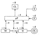
- An engine (1) is connected to a transmission (2) via a main clutch (3).
- the gearbox is connected on the output side with drive wheels (4).
- the transmission is controlled by a transmission control electronics (5).
- the equipped with one or more microprocessors ( ⁇ P) transmission control electronics (5) receives via a line (9) information about the speed of the motor (1).
- ⁇ P microprocessors
- Via another line (10) receives the transmission control electronics (5) information about the switching state of the main clutch (3). It can, for. B. by a button (not shown) can be determined whether the clutch (3) is closed or opened.
- the transmission control electronics (5) receives information about the respective Switching state of the (force-controlled) gearbox (2). Switching commands can also be supplied to the transmission via the same line (11). Next can be sensed via the line (11) input and output speed of the transmission (2).
- the respective shift position of the clutch (3) can also be determined via the input and output rotational speeds of the clutch (3) instead of a (complex) extra sensor.
- the clutch (3) is considered closed when both speeds are equal. In this case, however, the position of the clutch can only be checked after starting the engine.
- the transmission control (5) is further supplied information about the position of an ignition key (6). Further, the transmission control electronics (5) with a switching command generator (7) is connected by which gears can be switched on or preselected. Finally, the transmission control electronics (5) is connected to a signal transmitter (8).
- the operation of the gear shift according to the invention is such that in the electronics (5) after switching on the ignition key (6) is checked during the preheating of the engine, whether the transmission (2) is in the neutral position, or actuates the clutch (3); ie is open. If this is not the case, the signal generator (8) is activated. This will prompt the driver to operate the clutch (3) after turning on the ignition, but before actually starting the engine (1). However, this only happens if a dangerous condition actually exists.
- the signal generator (8) is executed as a display, which indicates a non-flashing "CL" (for clutch).
- the warning goes off as soon as the engine is started.
Landscapes
- Engineering & Computer Science (AREA)
- Chemical & Material Sciences (AREA)
- Combustion & Propulsion (AREA)
- Transportation (AREA)
- Mechanical Engineering (AREA)
- Control Of Transmission Device (AREA)
- Control Of Driving Devices And Active Controlling Of Vehicle (AREA)
- Auxiliary Drives, Propulsion Controls, And Safety Devices (AREA)
Description
- Die Erfindung bezieht sich auf eine halbautomatische Gangschaltung für Kraftfahrzeuge, insbesondere für Nutzfahrzeuge mit Dieselmotor gemäß dem Oberbegriff des Patentanspruchs 1.
- Kraftfahrzeuge mit Dieselmotor werden bekanntlich so gestartet, daß der Zündschlüssel zunächst in eine Vorglüh-Stellung geschaltet wird. Dann muß eine bestimmte Zeit abgewartet werden, bis der Vorglüh-Vorgang abgeschlossen ist. Anschließend kann der Schlüssel weitergedreht werden, wodurch der elektrische Anlasser des Motors eingeschaltet wird. Durch diesen Startvorgang wird der Dieselmotor in Gang gesetzt und läuft anschließend mit Leerlaufdrehzahl weiter. Bei manchen Fahrzeugen wird der Anlasser auch nicht durch den Zündschlüssel, sondern durch einen besonderen Knopf betätigt.
- Unter einer halbautomatischen Gangschaltung wird hier eine Gangschaltung verstanden, bei der noch eine vom Fahrer zu betätigende Kupplung vorhanden ist. Die Gänge werden mit einem elektrischen Geber eingelegt bzw. vorgewählt. Der Geber kann z. B. als Schritt-Schalter ausgebildet sein. Zwischen Geber und Getriebe ist keine mechanische Verbindung mehr vorhanden. Die Übermittlung der Schaltsignale erfolgt statt dessen über elektrische Leitungen ("shift by wire"). Der Fahrer erhält durch den Geber keine unmittelbare Information darüber, ob gerade ein Gang eingelegt ist.
- Bei dem geschilderten Anlaßvorgang ist es nun unbedingt nötig, daß entweder das Getriebe in der Neutralstellung steht, oder die Kupplung getreten (d. h. gelöst) ist. Wenn nämlich irrtümlicherweise beim Startvorgang des Motors die Hauptkupplung geschlossen ist und gleichzeitig ein Gang eingelegt ist, besteht die Gefahr, daß das Fahrzeug sich sprungartig in Bewegung setzt, der Motor abgewürgt wird, öder das Getriebe beschädigt wird.
- Eine Gefahr, daß ein Fahrer Kupplungsstellung und Getriebestellung vor dem Motorstart nicht nochmals kontrolliert, besteht besonders bei Fahrzeugen mit einem halbautomatischen Getriebe (SBW = shift by wire).
- Aus der JP-A-09169224 ist eine Schutzvorrichtung zum Starten von Arbeitsmaschinen, insbesondere Erntemaschinen bekannt. Derartige Maschinen haben Hilfsantriebe zum Betreiben von verschiedenen Arbeitsgeräten, die von dem Hauptantriebsmotor der Maschine über eigene Kupplungen mit antreibbar sind.
- Um zu verhindern, dass beim Starten des Hauptmotors diese Arbeitsgeräte unbeabsichtigt anspringen, wird vor dem Starten des Motors geprüft, ob die Kupplungen der Arbeitsmaschinen getrennt sind. Falls dies nicht der Fall ist, wird eine Warnanzeige angesteuert. Falls die Kupplungen nicht getrennt sind, wird außerdem ein Starten des Motors nicht zugelassen.
- Der Erfindung liegt die Aufgabe zugrunde, den oben beschriebenen gefährlichen Fahrzustand möglichst zu vermeiden.
- Diese Aufgabe wird durch die im Patentanspruch 1 enthaltene Erfindung gelöst. Die Unteransprüche enthalten zweckmäßige Weiterbildungen.
- Durch die Ergänzung der halbautomatischen Gangschaltung mit dem erfindungsgemäßen Kupplungs-Signalgeber wird auch ein unaufmerksamer Fahrer nochmals dazu aufgefordert, vor dem Anlassen des Motors die Kupplung zu treten.
- Es ist zwar bereits eine Getriebesteuerung mit einer Warnanzeige (Display) für den Zustand der Kupplung bekannt (EP 0 884 212 A1). Hier verfolgt die Kupplungs-Anzeige jedoch einen anderen Zweck, und zwar wird der Fahrer hier davor gewarnt, daß die Hauptkupplung nicht richtig geschlossen ist.
- Die Erfindung wird im folgenden anhand einer Zeichnung näher erläutert. Dargestellt ist in schematischer Weise ein Blockschaltbild einer halbautomatischen Gangschaltung in einem Kraftfahrzeug.
- Ein Motor (1) ist über eine Hauptkupplung (3) mit einem Getriebe (2) verbunden. Das Getriebe ist ausgangsseitig mit Antriebsrädern (4) verbunden.
- Das Getriebe wird von einer'Getriebesteuer-Elektronik (5) gesteuert. Die mit einem oder mehreren Mikroprozessoren (µP) ausgerüstete Getriebesteuer-Elektronik (5) erhält über eine Leitung (9) eine Information über die Drehzahl des Motors (1). Gegebenenfalls kann über die Leitung (9) auch die Drehzahl des Motors (1) beeinflußt werden. Über eine weitere Leitung (10) erhält die Getriebesteuer-Elektronik (5) eine Information über den Schaltzustand der Hauptkupplung (3). Es kann z. B. durch einen Taster (nicht dargestellt) ermittelt werden, ob die Kupplung (3) geschlossen oder geöffnet ist. Über eine weitere Leitung (11) erhält die Getriebesteuer-Elektronik (5) Informationen über den jeweiligen Schaltzustand des (fremdkraftgesteuerten) Getriebes (2). Über dieselbe Leitung (11) können dem Getriebe auch Schaltbefehle zugeführt werden. Weiter können über die Leitung (11) Eingangs- und Ausgangsdrehzahl des Getriebes (2) abgefühlt werden.
- Die jeweilige Schaltstellung der Kupplung (3) kann anstatt mit einem (aufwendigen) extra Sensor auch über die Eingangs- und Ausgangsdrehzahlen der Kupplung (3) bestimmt werden. Die Kupplung (3) gilt dann als geschlossen, wenn beide Drehzahlen gleich sind. In diesem Fall kann die Stellung der Kupplung aber erst nach Anlauf des Motors geprüft werden.
- Der Getriebesteuerung (5) wird weiter eine Information über die Stellung eines Zündschlüssels (6) zugeführt. Weiter ist die Getriebesteuer-Elektronik (5) mit einem Schaltbefehlsgeber (7) verbunden, durch welchen Gänge eingeschaltet oder vorgewählt werden können. Schließlich ist die Getriebesteuer-Elektronik (5) mit einem Signalgeber (8) verbunden.
- Die Funktionsweise der erfindungsgemäßen Gangschaltung ist so, daß in der Elektronik (5) nach dem Einschalten des Zündschlüssels (6) während des Vorglühens des Motors geprüft wird, ob das Getriebe (2) in der Neutralstellung steht, oder die Kupplung (3) betätigt; d. h. geöffnet ist. Falls dies nicht der Fall ist, wird der Signalgeber (8) angesteuert. Hierdurch wird der Fahrer aufgefordert, nach dem Einschalten der Zündung, aber vor dem eigentlichen Starten des Motors (1), die Kupplung (3) zu betätigen. Dies erfolgt aber nur, wenn tatsächlich ein gefährlicher Zustand vorliegt.
- Zweckmäßig wird der Signalgeber (8) als Display ausgeführt, wobei dieses ein nicht blinkendes "CL" (für Clutch) anzeigt.
- Es ist aber natürlich auch möglich, eine Warnlampe, einen Warnton, oder ein blinkendes Display vorzusehen.
- Die Warnung erlischt, sobald der Motor gestartet ist.
Claims (3)
- Halbautomatische Gangschaltung für ein Nutzfahrzeug mit Dieselmotor (1), wobei der Motor (1) über eine Hauptkupplung (3) mit einem Getriebe (2) verbunden ist, gekennzeichnet durch folgende Merkmale:a) Nach dem Einschalten des Zündschlüssels (6) während des Vorglühens wird von einer Getriebesteuer-Elektronik (5) geprüft, ob das Getriebe (2) in der Neutralstellung steht, oder ob die Kupplung (3) betätigt ist;b) falls das Getriebe (2) nicht in der Neutralstellung steht, oder die Kupplung (3) nicht betätigt ist, wird ein Signalgeber (8) angesteuert, der den Fahrer auffordert, nach dem Einschalten der Zündung, aber vor dem eigentlichen Starten des Motors (1) die Kupplung (3) zu betätigen.
- Gangschaltung nach Anspruch 1, dadurch gekennzeichnet, dass als Signalgeber (8) ein Display angesbeuert wird.
- Gangschaltung nach Anspruch 2, dadurch gekennzeichnet, dass das Display ein nicht blinkendes "CL" anzeigt.
Applications Claiming Priority (2)
| Application Number | Priority Date | Filing Date | Title |
|---|---|---|---|
| DE19925758A DE19925758A1 (de) | 1999-06-05 | 1999-06-05 | Gangschaltung für Kraftfahrzeuge |
| DE19925758 | 1999-06-05 |
Publications (3)
| Publication Number | Publication Date |
|---|---|
| EP1057686A2 EP1057686A2 (de) | 2000-12-06 |
| EP1057686A3 EP1057686A3 (de) | 2004-01-14 |
| EP1057686B1 true EP1057686B1 (de) | 2006-03-15 |
Family
ID=7910334
Family Applications (1)
| Application Number | Title | Priority Date | Filing Date |
|---|---|---|---|
| EP00106512A Expired - Lifetime EP1057686B1 (de) | 1999-06-05 | 2000-03-25 | Gangschaltung für Kraftfahrzeuge |
Country Status (3)
| Country | Link |
|---|---|
| US (1) | US6271749B1 (de) |
| EP (1) | EP1057686B1 (de) |
| DE (2) | DE19925758A1 (de) |
Families Citing this family (6)
| Publication number | Priority date | Publication date | Assignee | Title |
|---|---|---|---|---|
| DE10241995A1 (de) * | 2002-09-11 | 2004-03-18 | Zf Friedrichshafen Ag | Verfahren und Vorrichtung zur Rückmeldung eines Signals an den Fahrer eines Kraftfahrzeuges |
| FR2904395B1 (fr) * | 2006-07-31 | 2008-10-10 | Peugeot Citroen Automobiles Sa | Procede de determination de l'etat de point mort d'une boite de vitesses de vehicule automobile |
| DE102006053515A1 (de) * | 2006-11-14 | 2008-05-15 | GM Global Technology Operations, Inc., Detroit | Kraftfahrzeug mit einer Start-Stopp-Funktion für einen Verbrennungsmotor sowie Betriebsverfahren dafür |
| JP4876160B2 (ja) * | 2009-09-11 | 2012-02-15 | 本田技研工業株式会社 | エンジン始動装置 |
| DE102013001019A1 (de) * | 2013-01-22 | 2014-07-24 | GM Global Technology Operations LLC (n. d. Ges. d. Staates Delaware) | Verfahren zum Auslösen eines Warnsignals bei einem Fehlverhalten beim Betrieb eines Kraftfahrzeugs |
| CN103963646B (zh) * | 2014-05-21 | 2016-06-29 | 北京航天万达高科技有限公司 | 一种防止车辆误启动的止锁装置 |
Family Cites Families (19)
| Publication number | Priority date | Publication date | Assignee | Title |
|---|---|---|---|---|
| DE2036732C3 (de) * | 1970-07-24 | 1979-05-23 | Robert Bosch Gmbh, 7000 Stuttgart | Anordnung zum synchronisierten Schalten von Stufenwechselgetrieben in Fahrzeugen |
| US4871944A (en) * | 1979-02-13 | 1989-10-03 | North American Philips Corp. | Compact lighting unit having a convoluted fluorescent lamp with integral mercury-vapor pressure-regulating means, and method of phosphor-coating the convoluted envelope for such a lamp |
| US4295540A (en) * | 1979-09-14 | 1981-10-20 | Towmotor Corporation | Vehicle brake and engine interlock |
| JPS5810246A (ja) * | 1981-07-13 | 1983-01-20 | Nissan Motor Co Ltd | 車両用ディジタル制御装置 |
| JPS6264631A (ja) * | 1985-09-14 | 1987-03-23 | Nissan Shatai Co Ltd | エンジン始動制御装置 |
| JPH0784147B2 (ja) * | 1986-10-15 | 1995-09-13 | セイレイ工業株式会社 | 乗用作業車のスタ−タ回路 |
| JPS63192623A (ja) * | 1987-02-03 | 1988-08-10 | Mazda Motor Corp | 車両用電装品制御装置 |
| US5301565A (en) * | 1987-02-26 | 1994-04-12 | Weismann Peter H | Transmission |
| US4871994A (en) * | 1987-07-21 | 1989-10-03 | Nissan Motor Co., Ltd. | Alarm apparatus for automatic transmission vehicle |
| JP3208137B2 (ja) * | 1990-01-02 | 2001-09-10 | オートモティブ プロダクツ(ユーエスエイ) インコーポレイテッド | 電気制御装置 |
| US5015991A (en) * | 1990-03-27 | 1991-05-14 | Barr William A | Alarm system for vehicle automatic transmission |
| US5181592A (en) * | 1990-06-11 | 1993-01-26 | Sparton Corporation | Shift lever interlock system |
| US5252861A (en) * | 1991-07-18 | 1993-10-12 | Eaton Corporation | Starter interlock for electronically controlled vehicle |
| US5251733A (en) * | 1992-07-31 | 1993-10-12 | Deere & Company | Transmission control with limp-home function |
| US5485141A (en) * | 1993-12-17 | 1996-01-16 | Gregory; Jay D. | Logalert |
| US5581233A (en) * | 1995-06-06 | 1996-12-03 | Barr; William A. | Vehicle door lock, shift lever interlock system |
| JPH09169224A (ja) * | 1995-12-20 | 1997-06-30 | Seirei Ind Co Ltd | 動力作業車の始動安全装置 |
| DE19746149B4 (de) * | 1996-11-02 | 2007-07-12 | Volkswagen Ag | Verfahren und Vorrichtung zur Steuerung einer automatisierten Kupplung |
| US6052637A (en) | 1997-06-09 | 2000-04-18 | Eaton Corporation | Clutch adjustment determination |
-
1999
- 1999-06-05 DE DE19925758A patent/DE19925758A1/de not_active Ceased
-
2000
- 2000-03-25 EP EP00106512A patent/EP1057686B1/de not_active Expired - Lifetime
- 2000-03-25 DE DE50012388T patent/DE50012388D1/de not_active Expired - Lifetime
- 2000-05-30 US US09/583,117 patent/US6271749B1/en not_active Expired - Lifetime
Also Published As
| Publication number | Publication date |
|---|---|
| DE19925758A1 (de) | 2000-12-07 |
| US6271749B1 (en) | 2001-08-07 |
| EP1057686A3 (de) | 2004-01-14 |
| EP1057686A2 (de) | 2000-12-06 |
| DE50012388D1 (de) | 2006-05-11 |
Similar Documents
| Publication | Publication Date | Title |
|---|---|---|
| DE60118344T2 (de) | Steuerungsverfahren- und vorrichtung eines hybridfahrzeuges | |
| EP2181278B1 (de) | Verfahren zur ansteuerung der neutralposition in einem automatischen oder automatisierten getriebe eines kraftfahrzeugs und entsprechendes kraftfahrzeug | |
| DE69908843T2 (de) | Getriebe mit elektrischer Schaltbetätigung und Anzeige zur Kupplungsbetätigung | |
| DE102015119706B4 (de) | Fahrzeugsteuersystem und Verfahren zum Verwenden desselben | |
| DE10154429A1 (de) | Kraftübertragungssteuerung für Fahrzeuge | |
| DE102012217207B4 (de) | Verfahren und Vorrichtung zum Ansteuern eines Antriebsstrangs eines Fahrzeugs | |
| DE60008957T2 (de) | Steuerungssystem für die Überbrückungskupplung eines Momentwandlers | |
| EP0581124A2 (de) | Getriebesteuerung mit Notbetriebsfunktion | |
| DE4441896B4 (de) | Steuerung für ein Kraftfahrzeug | |
| DE19982154B4 (de) | Verfahren zur Start/Stop-Steuerung eines Kraftfahrzeuges mit automatisierter Kupplung | |
| WO2016180606A1 (de) | Steuervorrichtung in einem kraftfahrzeug mit einem elektronisch steuerbaren automatikgetriebe im answendungsfall waschstrasse | |
| DE19507622B4 (de) | Verfahren und Antriebsanordnung zur Steuerung des Motorbremsbetriebes eines Kraftfahrzeuges | |
| DE102008020184A1 (de) | Verfahren und Vorrichtung zum Steuern einer Stopp/Startfunktion einer Brennkraftmaschine | |
| DE19719615B4 (de) | Vorrichtung zur automatisierten Betätigung eines Drehmomentübertragungssystems | |
| DE102007040671A1 (de) | Verfahren zur Ansteuerung einer Fahrstufe in einem automatischen oder automatisierten Getriebe eines Kraftfahrzeugs | |
| DE19621950C2 (de) | Stop-Start-Einrichtung für eine Brennkraftmaschine eines Kraftfahrzeuges | |
| WO2009037158A2 (de) | Verfahren und vorrichtung zur beeinflussung der zugkraft während schaltvorgängen eines schaltgetriebes bei fahrzeugen | |
| DE112019005291T5 (de) | Verfahren zur steuerung eines getriebegangs als reaktion auf einen verlust der kommunikation mit einem motor und system hierfür | |
| EP1057686A2 (de) | Gangschaltung für Kraftfahrzeuge | |
| EP1879768B1 (de) | Verfahren zum aktivieren eines rangiermodus eines kraftfahrzeuges | |
| DE10157506A1 (de) | Kraftfahrzeug und Vefahren zum Betreiben eines Kraftfahrzeuges | |
| EP1662185B1 (de) | Verfahren und Steuerungsvorrichtung zum sicheren Trennen eines Antriebsstranges | |
| WO2010052047A1 (de) | Starteranordnung mit nebenaggregateantrieb | |
| WO2008052622A1 (de) | Kraftfahrzeugantrieb | |
| DE10234083B4 (de) | Starteinrichtung für ein Kraftfahrzeug |
Legal Events
| Date | Code | Title | Description |
|---|---|---|---|
| PUAI | Public reference made under article 153(3) epc to a published international application that has entered the european phase |
Free format text: ORIGINAL CODE: 0009012 |
|
| AK | Designated contracting states |
Kind code of ref document: A2 Designated state(s): AT BE CH CY DE DK ES FI FR GB GR IE IT LI LU MC NL PT SE |
|
| AX | Request for extension of the european patent |
Free format text: AL;LT;LV;MK;RO;SI |
|
| PUAL | Search report despatched |
Free format text: ORIGINAL CODE: 0009013 |
|
| AK | Designated contracting states |
Kind code of ref document: A3 Designated state(s): AT BE CH CY DE DK ES FI FR GB GR IE IT LI LU MC NL PT SE |
|
| AX | Request for extension of the european patent |
Extension state: AL LT LV MK RO SI |
|
| RIC1 | Information provided on ipc code assigned before grant |
Ipc: 7B 60K 41/02 A Ipc: 7B 60K 28/10 B |
|
| 17P | Request for examination filed |
Effective date: 20040714 |
|
| AKX | Designation fees paid |
Designated state(s): DE GB SE |
|
| 17Q | First examination report despatched |
Effective date: 20040906 |
|
| GRAP | Despatch of communication of intention to grant a patent |
Free format text: ORIGINAL CODE: EPIDOSNIGR1 |
|
| GRAS | Grant fee paid |
Free format text: ORIGINAL CODE: EPIDOSNIGR3 |
|
| GRAA | (expected) grant |
Free format text: ORIGINAL CODE: 0009210 |
|
| RIC1 | Information provided on ipc code assigned before grant |
Ipc: B60K 28/10 20060101AFI20060111BHEP |
|
| AK | Designated contracting states |
Kind code of ref document: B1 Designated state(s): DE GB SE |
|
| REG | Reference to a national code |
Ref country code: GB Ref legal event code: FG4D Free format text: NOT ENGLISH |
|
| REG | Reference to a national code |
Ref country code: SE Ref legal event code: TRGR |
|
| REF | Corresponds to: |
Ref document number: 50012388 Country of ref document: DE Date of ref document: 20060511 Kind code of ref document: P |
|
| GBT | Gb: translation of ep patent filed (gb section 77(6)(a)/1977) |
Effective date: 20060626 |
|
| RAP2 | Party data changed (patent owner data changed or rights of a patent transferred) |
Owner name: WABCO GMBH |
|
| PLBE | No opposition filed within time limit |
Free format text: ORIGINAL CODE: 0009261 |
|
| STAA | Information on the status of an ep patent application or granted ep patent |
Free format text: STATUS: NO OPPOSITION FILED WITHIN TIME LIMIT |
|
| 26N | No opposition filed |
Effective date: 20061218 |
|
| PGFP | Annual fee paid to national office [announced via postgrant information from national office to epo] |
Ref country code: GB Payment date: 20190325 Year of fee payment: 20 Ref country code: DE Payment date: 20190331 Year of fee payment: 20 |
|
| PGFP | Annual fee paid to national office [announced via postgrant information from national office to epo] |
Ref country code: SE Payment date: 20190325 Year of fee payment: 20 |
|
| REG | Reference to a national code |
Ref country code: GB Ref legal event code: PE20 Expiry date: 20200324 |
|
| PG25 | Lapsed in a contracting state [announced via postgrant information from national office to epo] |
Ref country code: GB Free format text: LAPSE BECAUSE OF EXPIRATION OF PROTECTION Effective date: 20200324 |
|
| REG | Reference to a national code |
Ref country code: SE Ref legal event code: EUG |