EP1056153A2 - Antennenvorrichtung für ein Funktelefon in einem Fahrzeug - Google Patents
Antennenvorrichtung für ein Funktelefon in einem Fahrzeug Download PDFInfo
- Publication number
- EP1056153A2 EP1056153A2 EP00110409A EP00110409A EP1056153A2 EP 1056153 A2 EP1056153 A2 EP 1056153A2 EP 00110409 A EP00110409 A EP 00110409A EP 00110409 A EP00110409 A EP 00110409A EP 1056153 A2 EP1056153 A2 EP 1056153A2
- Authority
- EP
- European Patent Office
- Prior art keywords
- antenna
- contact spring
- vehicle
- radio telephone
- contact
- Prior art date
- Legal status (The legal status is an assumption and is not a legal conclusion. Google has not performed a legal analysis and makes no representation as to the accuracy of the status listed.)
- Withdrawn
Links
Images

Classifications
-
- H—ELECTRICITY
- H01—ELECTRIC ELEMENTS
- H01Q—ANTENNAS, i.e. RADIO AERIALS
- H01Q1/00—Details of, or arrangements associated with, antennas
- H01Q1/27—Adaptation for use in or on movable bodies
- H01Q1/32—Adaptation for use in or on road or rail vehicles
- H01Q1/325—Adaptation for use in or on road or rail vehicles characterised by the location of the antenna on the vehicle
- H01Q1/3275—Adaptation for use in or on road or rail vehicles characterised by the location of the antenna on the vehicle mounted on a horizontal surface of the vehicle, e.g. on roof, hood, trunk
-
- H—ELECTRICITY
- H01—ELECTRIC ELEMENTS
- H01Q—ANTENNAS, i.e. RADIO AERIALS
- H01Q1/00—Details of, or arrangements associated with, antennas
- H01Q1/08—Means for collapsing antennas or parts thereof
- H01Q1/10—Telescopic elements
Definitions
- Antenna device for a radio telephone in a vehicle which has a first Antenna has to realize telephone operation with optimal connection quality and a second antenna, at least if the first is damaged Telephone operation with limited connection quality enabled. That's what it is for first antenna on the vehicle advantageously at an exposed location, e.g. B. on the Surface of the vehicle body or in the window area attached, although a high performance gain both for sending and receiving enables, but in the event of a traffic accident with the motor vehicle to one Total failure.
- the second antenna serves after the failure of the first one Main antenna, especially after a traffic accident as an emergency antenna Establish a telephone connection to make a call for help.
- Vehicle phones are usually equipped with an outside or window antenna equipped, the local location primarily according to the requirements of a optimal reception and transmission quality is selected.
- the emergency antenna is out of order. That is, the The emergency antenna and the corresponding line are put into operation basically only during an emergency by manual or automatic Establish an emergency call.
- an emergency button actuated or the control of the air bags and / or belt tensioner sends at their Trigger a corresponding control signal to the radio telephone to this on the to switch the second antenna connection.
- cellular phones run with several Antenna connections and extended equipment periodically a test procedure through, in which the antennas are put into operation one by one and on Functionality are checked. This is done, for example, by comparison the strength of the received signal or according to EP 0 859 237 A1 by comparing the fed in and those reflected by the antenna line Power.
- an antenna switchover is known optional use of an internal or an external antenna Radiotelephones known.
- the internal antenna however, the built-in antenna in the radio telephone and the external antenna a car antenna, which has a flexible feed line and a Antenna connector is manually connected to the radio telephone.
- a Switching device on the RF module of the radio telephone disconnects the Own antenna from the module and connects the radio telephone with one Vehicle antenna, as soon as the antenna connector in one with contact springs equipped plug-in base of the radio telephone is introduced.
- the contact springs of the Plug-in bases form a switch, which connects the switching device with a corresponding control voltage supplied.
- the object of the invention is achieved in that in the radio telephone alternatively, the first and the second antenna via the same antenna line and operated a switch near the first antenna, which in the absence the first antenna is operated to the second antenna with the antenna line connect.
- the first antenna is over a holder with a fragile one Fastening element attached to the vehicle and mechanically with a Contact spring of the switch connected. This will make the contact spring against yours Spring force locked in a tensioned state.
- the second antenna is on one Contact element is connected, which is the counter contact to the clamped Contact spring forms.
- the first antenna is advantageously made of a break-proof material made while the fastener is made of a material with less Breaking strength is made.
- the fastening element can also be so be designed so that it has a predetermined breaking point. This ensures that at an unusually high external force, such as the Rollover of the vehicle, the antenna inevitably in the area of the holder breaks off.
- the contact spring is locked in the holder so that when canceling or Removing the antenna unlocked the second antenna Place the first one to be connected to the radio telephone.
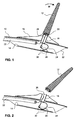
- a first antenna 12 is in the form of a conventional rod antenna outside on a vehicle roof 10 or on a other part of a vehicle body and a second antenna 14 under the Vehicle roof 10 attached.
- the antenna 12 is with a holder 16 on Vehicle roof 10 attached.
- the holder 16 is, as usual, made of non-conductive Material made and contains a fragile fastener in the form of a Hollow cylinder 18 with an external thread part 20, on which the antenna 12 is screwed.
- the hollow cylinder 18 is either at least in the range of Male thread part 20 made of metal or contains a conductor, which a establishes electrical connection from the antenna 12 to an antenna line 22.
- the antenna line 22 connects the antenna device to the radio telephone.
- the antenna 14, which is designed for example as a surface antenna and is located directly below the antenna 12 in the vehicle interior, has a contact element 28 on this forms a switch 30 with the contact spring 24, which in normal Operating state of the tension element 26 is kept open.
- the entire inner part of the Antenna device is common to the antenna-side end of the Antenna line 22 in an insulating housing 32 in the casing of the Vehicle roof 10 embedded so that with sufficient mechanical Stability of the vehicle roof 10 even in the event of an accident there is a risk of Destruction is very low.
- FIG. 2 shows the device according to the first exemplary embodiment in FIG destroyed state, i.e. after breaking off the antenna 12 in the area of Hollow cylinder 18.
- the external thread part 20 of the hollow cylinder 18 remains in the Inside the antenna 12.
- the pulling element 26 tears or breaks and gives the contact spring 24 free from its tensioned state. This relaxes and thereby strikes the contact element 28.
- the switch 30 closes one Connection between antenna line 22 and the antenna 14 and this occurs automatically in the place of the failed antenna 12.
- the antenna 14 instead of an additional antenna for the radio telephone, an antenna from another radio service, for example for radio broadcast reception or Satellite navigation can be used.
- the selection means for the separation of the frequency bands advantageously on the circuit board surface be accommodated.
- FIG. 3 and FIG. 4 show a further embodiment of the invention. This has the additional advantage that the antenna device can then also be used on the Antenna 14 switches over when antenna 12 is only unscrewed. This This feature allows the structure to be built even if the antenna 12 is forgotten or stolen an emergency connection.
- the first antenna 12 as a rod antenna on the vehicle roof 10 and the second antenna 14 below attached to the vehicle roof 10.
- the antenna 12 is on the vehicle roof 10 attached to the holder 16.
- the antenna 12 and the holder 16 differ from the first solution in that the antenna 12 has an externally threaded part 34 with which it is screwed into a threaded head 36 of the holder 16.
- the retractable contact spring 22 is replaced by an extended one under pressure reacting contact spring 38 which is clamped on one side in a holder 40.
- Case a curved contact element 42, which with the sheet-like antenna 14 is connected.
- the contact element 42 and the contact spring 38 form in this Embodiment switch 30.
- FIG. 4 shows the antenna device according to FIG. 3 with the antenna removed 12, for example for driving through a car wash.
- contact spring 38 is in contact with the contact element 42, since the contact spring 38 the contact pins 44 as a result of the missing antenna 12 pushes outward as a counter bearing.
- the antenna 14 instead of the dismantled antenna 12 now via the contact spring 38 and the contact element 42, the antenna 14 with the Antenna line 22 connected. This function is useful if you forget screw the antenna 12 back on or it is lost.
- the threaded head 36 in connection with a predetermined breaking point 46, which is located on the holder 16 below the threaded head 36.
- the predetermined breaking point 46 results from a considerable reduction in the Material cross section at this point.
- With an extreme mechanical Stress on the antenna 12 breaks the holder 16 at the predetermined breaking point 46, the antenna 12 remains in the broken threaded head 36. Leaving the contact pin 44 its original position and gives the pressure contact spring 38 free.
- the antenna 14 is used to carry out the emergency call function Antenna line 22 connected.
Landscapes
- Engineering & Computer Science (AREA)
- Remote Sensing (AREA)
- Details Of Aerials (AREA)
- Support Of Aerials (AREA)
- Mobile Radio Communication Systems (AREA)
Abstract
Description
- FIG. 1
- einer Antennenvorrichtung für ein Funktelefon in einem Fahrzeug in einer ersten Ausführungsform gemäss der Erfindung und in ihrem ursprünglichen Funktionszustand
- FIG. 2
- der Antennenvorrichtung gemäss FIG. 1 nach dem Abbrechen der Hauptantenne, beispielsweise einem Unfall
- FIG. 3
- einer weiteren Ausführungsform der Antennenvorrichtung gemäss der Erfindung in ihrem ursprünglichen Funktionszustand
- FIG. 4
- der Antennenvorrichtung gemäss FIG. 3 mit demontierter Hauptantenne
Claims (10)
- Antennenvorrichtung für ein Funktelefon in einem Fahrzeug mit einer ersten Antenne (12), welche zum Telefonieren bei optimaler Verbindungsqualität über eine Antennenleitung (22) mit dem Funktelefon verbunden ist, einer zweiten Antenne (14), welche bei einem Ausfall der ersten Antenne (12) zumindest Telefonieren mit eingeschränkter Verbindungsqualität ermöglicht, und mit einem elektrischen Schalter (30), der nach einem Ausfall der ersten Antenne (12) die zweite Antenne (14) an das Funktelefon schaltet, dadurch gekennzeichnet, dass die erste Antenne (12) mit einem zerbrechlichen Befestigungselement (18, 36) am Fahrzeug befestigt ist und dass der Schalter (30) beim Zerbrechen des Befestigungselements (18, 36) durch mechanische Mittel (24, 26 oder 38, 44) automatisch die zweite Antenne (14) an Stelle der ersten Antenne (12) mit der Antennenleitung (22) verbindet.
- Antennenvorrichtung nach Anspruch 1, dadurch gekennzeichnet,dass die erste Antenne (12) mit dem zerbrechlichen Befestigungselement (18, 36) in einem Halter (16) befestigt ist und mechanisch mit einer Kontaktfeder (24, 38) des Schalters (30) gekoppelt ist, um diese gegen ihre Federkraft in einem gespannten Zustand zu arretieren,dass die zweite Antenne (14) an einem Kontaktelement (28, 42) angeschlossen ist, welches mit der gespannten Kontaktfeder (24, 38) den Schalter (30) bildetund dass Kontaktfeder (24, 38) und erste Antenne (12) derart miteinander verbunden sind, dass sowohl ein Zerbrechen des Befestigungselements (18, 36) am Halter (16) als auch ein Fehlen der ersten Antenne (12) im Halter die Arretierung der Kontaktfeder (24, 38) aufhebt und die zweite Antenne (14) an die Stelle der ersten mit der Antennenleitung (22) verbindet.
- Antennenvorrichtung nach Anspruch 1, dadurch gekennzeichnet, dass das Befestigungselement (18) aus starrem Material und die erste Antenne (12) aus unzerbrechlichem Material oder einem Material mit einer hohen Bruchfestigkeit besteht, so dass bei einer hohen äusseren Krafteinwirkung an Stelle der ersten Antenne (12) zwangsläufig das Befestigungselement (18) bricht und dabei den elektrischen Schalter (30) schließt.
- Antennenvorrichtung nach Anspruch 1 und 2, dadurch gekennzeichnet, dass das Befestigungselement (36) ein Teil des Halters (16) ist, welcher bei einer hohen äusseren Krafteinwirkung auf die erste Antenne (12) an einer Sollbruchstelle (46) bricht.
- Antennenvorrichtung nach Anspruch 1, dadurch gekennzeichnet, dass sich das Kontaktelement (28, 42) im Innern des Fahrzeugs nahe des Befestigungselements (18, 36) befindet und dass an der Antennenleitung (22) zur ersten Antenne (12) die Kontaktfeder (24) angeordnet ist.
- Antennenvorrichtung nach Anspruch 4, dadurch gekennzeichnet, dass die zweite Antenne (14) als Fläche ausgeführt ist, auf der sich das Kontaktelement (28, 42) befindet.
- Antennenvorrichtung nach Anspruch 1, dadurch gekennzeichnet, dass die Kontaktfeder (24) mit einem Zugelement (26) gespannt wird, welches an dem Teil (20) des Befestigungselements (18) angebracht ist, das sich im Innern der ersten Antenne (12) befindet, so dass sich nur beim Abbrechen der ersten Antenne (12) die Arretierung der Kontaktfeder (24) löst.
- Antennenvorrichtung nach Anspruch 1, dadurch gekennzeichnet, dass sich zwischen der ersten Antenne (12) ein Druckelement (44) aufweist, das die Kontaktfeder (38) und das Kontaktelement (42) solange auseinander drückt, wie sich die erste Antenne (12) im Halter (16) befindet.
- Antennenvorrichtung nach Anspruch 1, dadurch gekennzeichnet, dass die Antenne 14 eine Antenne von einem anderen Funkdienst ist der in einem anderen Frequenzband arbeitet.
- Antennenvorrichtung nach Anspruch 9, dadurch gekennzeichnet, dass Selektionsmittel für die Trennung der Frequenzbänder mit dem Schalter (30) vereinigt sind.
Applications Claiming Priority (2)
| Application Number | Priority Date | Filing Date | Title |
|---|---|---|---|
| DE19923661 | 1999-05-22 | ||
| DE19923661A DE19923661A1 (de) | 1999-05-22 | 1999-05-22 | Antennenvorrichtung für ein Funktelefon in einem Fahrzeug |
Publications (2)
| Publication Number | Publication Date |
|---|---|
| EP1056153A2 true EP1056153A2 (de) | 2000-11-29 |
| EP1056153A3 EP1056153A3 (de) | 2003-06-04 |
Family
ID=7908951
Family Applications (1)
| Application Number | Title | Priority Date | Filing Date |
|---|---|---|---|
| EP00110409A Withdrawn EP1056153A3 (de) | 1999-05-22 | 2000-05-16 | Antennenvorrichtung für ein Funktelefon in einem Fahrzeug |
Country Status (3)
| Country | Link |
|---|---|
| US (1) | US6275194B1 (de) |
| EP (1) | EP1056153A3 (de) |
| DE (1) | DE19923661A1 (de) |
Cited By (1)
| Publication number | Priority date | Publication date | Assignee | Title |
|---|---|---|---|---|
| EP1646106A1 (de) * | 2004-10-06 | 2006-04-12 | Rosenberger Hochfrequenztechnik GmbH & Co. KG | Steckanordnung für HF-Signalweg |
Families Citing this family (18)
| Publication number | Priority date | Publication date | Assignee | Title |
|---|---|---|---|---|
| US6535171B1 (en) * | 2001-06-25 | 2003-03-18 | General Motors Corporation | Vehicle vent through an opening in a radio antenna base |
| ITVI20020213A1 (it) * | 2002-10-15 | 2004-04-16 | Calearo Srl | Coperchio per antenne veicolari. |
| KR100540229B1 (ko) * | 2003-02-25 | 2006-01-10 | 엘지전자 주식회사 | 이동통신 단말기의 송신단 성능 개선 장치 및 그 방법 |
| DE102005040604B4 (de) * | 2005-08-23 | 2009-02-26 | Siemens Ag | Verfahren zum Umschalten von einer ersten Antenne eines Funkmoduls auf eine zweite Antenne des Funkmoduls |
| JP4652950B2 (ja) * | 2005-10-31 | 2011-03-16 | 原田工業株式会社 | 着脱式車両用アンテナ |
| DE102006025176C5 (de) * | 2006-05-30 | 2023-02-23 | Continental Automotive Technologies GmbH | Antennenmodul für ein Fahrzeug |
| DE102007026607A1 (de) * | 2007-06-08 | 2008-12-11 | Bayerische Motoren Werke Aktiengesellschaft | Kraftfahrzeug |
| KR100989547B1 (ko) * | 2008-05-19 | 2010-10-25 | 박진우 | 안테나 접속장치 |
| US8583199B2 (en) * | 2011-04-07 | 2013-11-12 | General Motors Llc | Telematics systems and methods with multiple antennas |
| US9297844B2 (en) | 2012-08-24 | 2016-03-29 | GM Global Technology Operations LLC | Antenna mast detection methods and systems |
| KR20150003551A (ko) * | 2013-07-01 | 2015-01-09 | 현대자동차주식회사 | 이동통신 서비스를 위한 차량용 안테나 |
| KR101481287B1 (ko) * | 2013-07-01 | 2015-01-14 | 현대자동차주식회사 | 이동통신 서비스를 위한 차량용 안테나 |
| DE102013222951A1 (de) * | 2013-11-12 | 2015-05-13 | Bayerische Motoren Werke Aktiengesellschaft | Antennenbaugruppe für ein Kraftfahrzeug und Kraftfahrzeug mit der Antennenbaugruppe |
| US10044415B2 (en) * | 2014-12-05 | 2018-08-07 | Murata Manufacturing Co., Ltd. | System, method, and module for RF-signal coverage for automotive vehicles |
| FR3031629B1 (fr) * | 2015-01-08 | 2017-01-13 | Peugeot Citroen Automobiles Sa | Dispositif de fusible mecanique d’escamotage pour antenne de vehicule |
| FR3063194B1 (fr) * | 2017-02-23 | 2019-04-26 | Valeo Comfort And Driving Assistance | Dispositif et procede de communication |
| JP7055698B2 (ja) | 2018-05-09 | 2022-04-18 | アルパイン株式会社 | 通信装置、通信システム |
| US11223114B2 (en) * | 2019-12-27 | 2022-01-11 | Harman International Industries, Incorporated | Antenna system for a vehicle telematics unit |
Family Cites Families (10)
| Publication number | Priority date | Publication date | Assignee | Title |
|---|---|---|---|---|
| DE859237C (de) | 1944-01-21 | 1952-12-11 | Daimler Benz Ag | Verbrennungskraftmaschine, bei welcher zeitweilig die Auspuffgase zur Ladung der Maschine benutzt werden |
| DE2546260C3 (de) * | 1975-10-16 | 1980-01-03 | Securiton Ag, Zollikofen, Bern (Schweiz) | Stabantenne |
| JPH04123955A (ja) * | 1990-09-14 | 1992-04-23 | Matsushita Electric Works Ltd | 車輌盗難報知装置 |
| JP2598028Y2 (ja) * | 1991-01-31 | 1999-07-26 | 第一電子工業 株式会社 | 小型電気切換器 |
| US5714959A (en) * | 1994-06-09 | 1998-02-03 | Delco Electronics Corporation | Glass patch cellular antenna |
| JP3225837B2 (ja) * | 1996-04-19 | 2001-11-05 | 松下電器産業株式会社 | 高周波信号受信装置 |
| GB9700531D0 (en) * | 1997-01-13 | 1997-03-05 | Decolletage Sa Saint Maurice | Coaxial switch connector assembly |
| TW317067B (en) * | 1997-01-23 | 1997-10-01 | Acer Peripherals Inc | Antenna switching device used in radio handheld set |
| DE19705735A1 (de) * | 1997-02-14 | 1998-08-20 | Nokia Mobile Phones Ltd | Verfahren und Vorrichtung zur Inspektion wenigstens eines Antennenzweigs, insbesondere in einem Fahrzeug |
| DE19752189C2 (de) * | 1997-11-25 | 2000-06-08 | Meinen Ziegel & Co Gmbh | Mobiltelefon, bestehend aus einer oder mehreren IC-Karten |
-
1999
- 1999-05-22 DE DE19923661A patent/DE19923661A1/de not_active Withdrawn
-
2000
- 2000-05-16 EP EP00110409A patent/EP1056153A3/de not_active Withdrawn
- 2000-05-22 US US09/575,441 patent/US6275194B1/en not_active Expired - Fee Related
Cited By (1)
| Publication number | Priority date | Publication date | Assignee | Title |
|---|---|---|---|---|
| EP1646106A1 (de) * | 2004-10-06 | 2006-04-12 | Rosenberger Hochfrequenztechnik GmbH & Co. KG | Steckanordnung für HF-Signalweg |
Also Published As
| Publication number | Publication date |
|---|---|
| DE19923661A1 (de) | 2000-11-23 |
| EP1056153A3 (de) | 2003-06-04 |
| US6275194B1 (en) | 2001-08-14 |
Similar Documents
| Publication | Publication Date | Title |
|---|---|---|
| DE19923661A1 (de) | Antennenvorrichtung für ein Funktelefon in einem Fahrzeug | |
| DE102006025176B4 (de) | Antennenmodul für ein Fahrzeug | |
| DE60133703T2 (de) | Eingebaute Zweibandantenne und Verfahren zum Betrieb dieser Antenne in einem mobilen Terminal | |
| EP1406345B1 (de) | PIFA-Antenne mit Zusatzinduktivität | |
| DE10207703B4 (de) | Antenne für eine Empfangs- und/oder Sendeeinrichtung insbesondere als Dachantenne für Kraftfahrzeuge | |
| DE60017674T2 (de) | Faltdipolantenne | |
| DE102009038150B4 (de) | Multiband-Antennenmodul für ein Fahrzeug | |
| DE4032013A1 (de) | Antennenvorrichtung zur gemeinsamen benutzung fuer drei frequenzbereiche | |
| DE2603606A1 (de) | Elektrische subminiatur-anschlussanordnung | |
| DE102019130860A1 (de) | Schraubbare Fahrzeugantenne | |
| DE10302805A1 (de) | Multibandantennenanordnung für Mobilfunkgeräte | |
| EP3518340A1 (de) | Hf-combiner für eine mobilfunk-site, hf-combineranordnung mit zwei hf-combinern für eine mobilfunk-site und eine solche mobilfunk-site | |
| DE69731861T2 (de) | Funkübertragungseinrichtung mit einer ausziehbaren Antenne und eine Antenne für eine solche Einrichtung | |
| DE102018205628A1 (de) | Hochvoltbatterie für ein Kraftfahrzeug | |
| DE102009038038B4 (de) | Antennenanordnung für ein Kraftfahrzeug und Kraftfahrzeug | |
| DE69735452T2 (de) | Tragbares Funkgerät | |
| DE69513195T2 (de) | Antennenanordnung für eine fahrzeugfensterscheibe | |
| EP2201643B1 (de) | Verfahren zur herstellung einer fahrzeugantenneneinrichtung | |
| DE69932013T2 (de) | Antenne für mobile funkkommunikation | |
| DE19823126B4 (de) | Funkgerät | |
| DE102007012617A1 (de) | Halter für portables Navigationsgerät | |
| DE102008053851A1 (de) | Antennenanlage, insbesondere Mobilfunk-Antennenanlage sowie zugehörige Übertragungs- und Steuerungseinrichtung | |
| DE102004036453A1 (de) | Antenne zur Anwendung für Kommunikation (Senden und/oder Empfangen) in einem Fahrzeug, insbesondere in einem Personenkraftwagen | |
| DE102023132202A1 (de) | Befestigung von Steuergeräten | |
| EP1421645A1 (de) | Antenne für dvb-t-empfang |
Legal Events
| Date | Code | Title | Description |
|---|---|---|---|
| PUAI | Public reference made under article 153(3) epc to a published international application that has entered the european phase |
Free format text: ORIGINAL CODE: 0009012 |
|
| AK | Designated contracting states |
Kind code of ref document: A2 Designated state(s): AT BE CH CY DE DK ES FI FR GB GR IE IT LI LU MC NL PT SE |
|
| AX | Request for extension of the european patent |
Free format text: AL;LT;LV;MK;RO;SI |
|
| RAP1 | Party data changed (applicant data changed or rights of an application transferred) |
Owner name: NOKIA CORPORATION |
|
| PUAL | Search report despatched |
Free format text: ORIGINAL CODE: 0009013 |
|
| AK | Designated contracting states |
Designated state(s): AT BE CH CY DE DK ES FI FR GB GR IE IT LI LU MC NL PT SE |
|
| AX | Request for extension of the european patent |
Extension state: AL LT LV MK RO SI |
|
| AKX | Designation fees paid | ||
| REG | Reference to a national code |
Ref country code: DE Ref legal event code: 8566 |
|
| STAA | Information on the status of an ep patent application or granted ep patent |
Free format text: STATUS: THE APPLICATION IS DEEMED TO BE WITHDRAWN |
|
| 18D | Application deemed to be withdrawn |
Effective date: 20031202 |