EP1056105B1 - Elektrisches Installationsgerät, insbesondere Leitungsschutzschalter - Google Patents
Elektrisches Installationsgerät, insbesondere Leitungsschutzschalter Download PDFInfo
- Publication number
- EP1056105B1 EP1056105B1 EP00110302A EP00110302A EP1056105B1 EP 1056105 B1 EP1056105 B1 EP 1056105B1 EP 00110302 A EP00110302 A EP 00110302A EP 00110302 A EP00110302 A EP 00110302A EP 1056105 B1 EP1056105 B1 EP 1056105B1
- Authority
- EP
- European Patent Office
- Prior art keywords
- arc
- generation region
- loop
- iron plate
- circuit breaker
- Prior art date
- Legal status (The legal status is an assumption and is not a legal conclusion. Google has not performed a legal analysis and makes no representation as to the accuracy of the status listed.)
- Expired - Lifetime
Links
- 238000010616 electrical installation Methods 0.000 title description 2
- XEEYBQQBJWHFJM-UHFFFAOYSA-N Iron Chemical compound [Fe] XEEYBQQBJWHFJM-UHFFFAOYSA-N 0.000 claims abstract description 18
- 229910052742 iron Inorganic materials 0.000 claims abstract description 9
- 238000009434 installation Methods 0.000 claims description 4
- 238000010791 quenching Methods 0.000 claims description 4
- 230000000171 quenching effect Effects 0.000 claims description 3
- 238000007664 blowing Methods 0.000 description 2
- 230000005672 electromagnetic field Effects 0.000 description 2
- 230000000694 effects Effects 0.000 description 1
- 230000005684 electric field Effects 0.000 description 1
Images
Classifications
-
- H—ELECTRICITY
- H01—ELECTRIC ELEMENTS
- H01H—ELECTRIC SWITCHES; RELAYS; SELECTORS; EMERGENCY PROTECTIVE DEVICES
- H01H9/00—Details of switching devices, not covered by groups H01H1/00 - H01H7/00
- H01H9/30—Means for extinguishing or preventing arc between current-carrying parts
- H01H9/34—Stationary parts for restricting or subdividing the arc, e.g. barrier plate
- H01H9/346—Details concerning the arc formation chamber
-
- H—ELECTRICITY
- H01—ELECTRIC ELEMENTS
- H01H—ELECTRIC SWITCHES; RELAYS; SELECTORS; EMERGENCY PROTECTIVE DEVICES
- H01H9/00—Details of switching devices, not covered by groups H01H1/00 - H01H7/00
- H01H9/30—Means for extinguishing or preventing arc between current-carrying parts
- H01H9/44—Means for extinguishing or preventing arc between current-carrying parts using blow-out magnet
- H01H9/446—Means for extinguishing or preventing arc between current-carrying parts using blow-out magnet using magnetisable elements associated with the contacts
Definitions
- the invention relates to an electrical installation device, in particular a circuit breaker, according to the preamble of claim 1.
- an installation device is known from document DE-195 249 15.
- Installation switchgear of this type serves for an overcurrent or a short-circuit current off.
- the contact pieces are arcing plates assigned, in the case of a switch-off between the fixed and arcing generated in the movable contact piece runs to its quenching.
- the object of the invention is to define the ring-shaped electromagnetic field, that is to say the blowing field, to strengthen and focus.
- an insulating plate is arranged on each of them, which defines the arcing area limited on both sides; is located behind the insulating plates an iron plate, the iron plate that is on the side of the loop, is arranged within the loop or the loop the iron sheet on his At least partially surrounds the outer circumference.
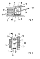
- Fig. 1 shows the arcing area of a circuit breaker, in which is a fixed contact piece 11 attached to an arc guide rail 10 as well as a movable contact piece 12, which is located on an axis 13 pivotable contact lever 14 is attached.
- a further arc guide rail 15 is assigned to the arcing area, which is composed of a plurality of arc-extinguishing plates 16 on both sides 17 limit.
- Fig. 2 shows the arrangement along section line II-II of Fig. 1.
- the loop 18 is located outside the insulating plate 22.
- a first iron plate 23 is provided inside the loop 18, that is practically in one plane therewith.
- a second iron plate 24 is provided inside the loop 18, that is practically in one plane therewith.
Landscapes
- Arc-Extinguishing Devices That Are Switches (AREA)
- Breakers (AREA)
- Emergency Protection Circuit Devices (AREA)
- Gas-Insulated Switchgears (AREA)
Description
- Fig. 1
- eine Schnittansicht eines Lichtbogenentstehungsbereiches gemäß Schnittlinie I-I der Fig. 2, und
- Fig. 2
- eine Schnittansicht gemäß Schnittlinie II-II der Fig. 1.
Claims (2)
- Elektrisches Installationsschaltgerät, insbesondere Leitungsschutzschalter, mit einem festen (11) und einem an einem schwenkbaren Kontakthebel (14) befestigten beweglichen (12) Kontaktstück, zwischen denen bei einer Ausschaltung ein Lichtbogen (19) entsteht, der, unterstützt von einem durch eine stromdurchflossene Schleife (18) erzeugten Blasfeld, in ein Lichtbogenlöschblechpaket (17) zur Löschung einläuft, dadurch gekennzeichnet, daß innerhalb der auf einer Seite des Lichtbogenentstehungsbereiches (20) angeordneten Schleife (18) eine erste Eisenplatte (23) angeordnet ist, und daß zwischen dem Lichtbogenentstehungsbereich (20) und der ersten Eisenplatte (23) eine erste isolierende Platte vorgesehen ist.
- Installationsschaltgerät nach Anspruch 1, dadurch gekennzeichnet, daß auf der anderen Seite des Lichtbogenentstehungsbereiches (20) eine weitere Isolierstoffplatte (21), die an den Lichtbogenentstehungsbereichen (20) angrenzt, und außerhalb der weiteren Isolierstoffplatte (21) eine zweite Eisenplatte (24) vorgesehen sind.
Applications Claiming Priority (2)
| Application Number | Priority Date | Filing Date | Title |
|---|---|---|---|
| DE19924414 | 1999-05-27 | ||
| DE19924414A DE19924414A1 (de) | 1999-05-27 | 1999-05-27 | Elektrisches Installationsgerät, insbesondere Leitungsschutzschalter |
Publications (3)
| Publication Number | Publication Date |
|---|---|
| EP1056105A2 EP1056105A2 (de) | 2000-11-29 |
| EP1056105A3 EP1056105A3 (de) | 2002-04-10 |
| EP1056105B1 true EP1056105B1 (de) | 2003-05-28 |
Family
ID=7909423
Family Applications (1)
| Application Number | Title | Priority Date | Filing Date |
|---|---|---|---|
| EP00110302A Expired - Lifetime EP1056105B1 (de) | 1999-05-27 | 2000-05-13 | Elektrisches Installationsgerät, insbesondere Leitungsschutzschalter |
Country Status (4)
| Country | Link |
|---|---|
| EP (1) | EP1056105B1 (de) |
| AT (1) | ATE241852T1 (de) |
| DE (2) | DE19924414A1 (de) |
| PL (1) | PL340281A1 (de) |
Families Citing this family (5)
| Publication number | Priority date | Publication date | Assignee | Title |
|---|---|---|---|---|
| DE10242310A1 (de) * | 2001-11-16 | 2003-07-10 | Abb Patent Gmbh | Lichtbogenlöschanordnung für ein elektrisches Schaltgerät |
| EP1313117B1 (de) | 2001-11-16 | 2014-06-04 | Abb Ag | Lichtbogenlöschanordnung für ein elektronisches Schaltgerät |
| DE102004032738A1 (de) * | 2004-07-07 | 2006-02-09 | Abb Patent Gmbh | Lichtbogeneinrichtung für ein elektrisches Schaltgerät |
| DE102005007282A1 (de) * | 2005-02-17 | 2006-08-24 | Abb Patent Gmbh | Elektrisches Installationsgerät mit Lichtbogen-Vorkammerraum, Vorkammerplatten und strombegrenzender Lichtbogenlöscheinrichtung |
| US9006601B2 (en) * | 2013-03-13 | 2015-04-14 | Eaton Corporation | Arc chamber for bi-directional DC |
Family Cites Families (6)
| Publication number | Priority date | Publication date | Assignee | Title |
|---|---|---|---|---|
| DE3334108A1 (de) * | 1983-09-21 | 1985-04-04 | Siemens AG, 1000 Berlin und 8000 München | Lichtbogenloeschsystem |
| DE3337562A1 (de) * | 1983-10-15 | 1985-04-25 | Licentia Patent-Verwaltungs-Gmbh, 6000 Frankfurt | Loescheinrichtung fuer einen leitungsschutzschalter |
| US4743720A (en) * | 1985-11-25 | 1988-05-10 | Matsushita Electric Works, Ltd. | Current limiting circuit interrupter |
| FR2622736B1 (fr) * | 1987-10-28 | 1995-04-14 | Merlin Gerin | Disjoncteur basse tension, a courant continu, et a joues de guidage de l'arc |
| DE19518049A1 (de) * | 1995-05-17 | 1996-11-21 | Abb Patent Gmbh | Lichtbogenlöscheinrichtung |
| DE19524915C2 (de) * | 1995-07-08 | 2003-06-26 | Abb Patent Gmbh | Lichtbogenlöschanordnung für einen elektrischen Schalter, insbesondere für einen Leitungsschutzschalter |
-
1999
- 1999-05-27 DE DE19924414A patent/DE19924414A1/de not_active Withdrawn
-
2000
- 2000-05-13 DE DE50002327T patent/DE50002327D1/de not_active Expired - Fee Related
- 2000-05-13 AT AT00110302T patent/ATE241852T1/de not_active IP Right Cessation
- 2000-05-13 EP EP00110302A patent/EP1056105B1/de not_active Expired - Lifetime
- 2000-05-25 PL PL00340281A patent/PL340281A1/xx unknown
Also Published As
| Publication number | Publication date |
|---|---|
| EP1056105A3 (de) | 2002-04-10 |
| PL340281A1 (en) | 2000-12-04 |
| EP1056105A2 (de) | 2000-11-29 |
| DE19924414A1 (de) | 2000-11-30 |
| ATE241852T1 (de) | 2003-06-15 |
| DE50002327D1 (de) | 2003-07-03 |
Similar Documents
| Publication | Publication Date | Title |
|---|---|---|
| DE102005007282A1 (de) | Elektrisches Installationsgerät mit Lichtbogen-Vorkammerraum, Vorkammerplatten und strombegrenzender Lichtbogenlöscheinrichtung | |
| EP2786388B1 (de) | Schaltgerät geeignet für einen gleichstrombetrieb | |
| EP1683173B1 (de) | Lichtbogen-löschvorrichtung | |
| DE3141958A1 (de) | "elektromagnetisch betaetigbarer elektrischer schalter" | |
| EP0158124B1 (de) | Lichtbogenlöscheinrichtung für elektrische Schalter | |
| DE2716619B1 (de) | Strombegrenzender Leitungsschutzschalter mit Massnahmen zur Erhoehung der Laufgeschwindigkeit des Schaltlichtbogens | |
| EP0444283B1 (de) | Leitungsschutzschalter mit einem elektromagnetischen Auslöseorgan | |
| DE3824027A1 (de) | Elektrisches schaltgeraet | |
| EP1056105A2 (de) | Elektrisches Installationsgerät, insbesondere Leitungsschutzschalter | |
| DE3337562A1 (de) | Loescheinrichtung fuer einen leitungsschutzschalter | |
| AT399065B (de) | Kontaktsystem zur begrenzung der lichtbogenlänge in einem fehlerstromschutzschalter | |
| EP2747107A1 (de) | Elektrisches Schaltgerät | |
| EP2541574B1 (de) | Doppeltunterbrechendes Schutzschaltgerät | |
| DE19517634C2 (de) | Elektrisches Installationsschaltgerät | |
| DE2734395A1 (de) | Einrichtung zur strombegrenzung | |
| DE102009035299B4 (de) | Kontaktsystem und Schaltgerät | |
| DE102005007301A1 (de) | Elektrisches Installationsgerät mit Lichtbogen-Vorkammerraum und strombegrenzender Lichtbogenlöscheinrichtung | |
| EP0164632B1 (de) | Lichtbogenlöscheinrichtung | |
| EP0624889B1 (de) | Elektrischer Schalter | |
| EP1693870A2 (de) | Elektrisches Installationsgerät mit Lichtbogen-Vorkammerraum, Lichtbogenleitschienen und strombegrenzender Lichtbogenlöscheinrichtung | |
| DE3412566A1 (de) | Lichtbogenloescheinrichtung fuer schaltgeraete der elektrischen energietechnik | |
| DE1665684A1 (de) | Elektrischer Schalter,insbesondere Leitungsschutzschalter | |
| EP0614207A2 (de) | Schaltgerät mit einem thermischen und einem magnetischen Auslöser | |
| EP0938121A3 (de) | Selbstschalter, insbesondere Niederspannungs-Schutzschalter | |
| DE4330369A1 (de) | Leitungsschutzschalter |
Legal Events
| Date | Code | Title | Description |
|---|---|---|---|
| PUAI | Public reference made under article 153(3) epc to a published international application that has entered the european phase |
Free format text: ORIGINAL CODE: 0009012 |
|
| AK | Designated contracting states |
Kind code of ref document: A2 Designated state(s): AT BE CH CY DE DK ES FI FR GB GR IE IT LI LU MC NL PT SE |
|
| AX | Request for extension of the european patent |
Free format text: AL;LT;LV;MK;RO;SI PAYMENT 20000520 |
|
| RAP1 | Party data changed (applicant data changed or rights of an application transferred) |
Owner name: ABB PATENT GMBH |
|
| PUAL | Search report despatched |
Free format text: ORIGINAL CODE: 0009013 |
|
| AK | Designated contracting states |
Kind code of ref document: A3 Designated state(s): AT BE CH CY DE DK ES FI FR GB GR IE IT LI LU MC NL PT SE |
|
| AX | Request for extension of the european patent |
Free format text: AL;LT;LV;MK;RO;SI PAYMENT 20000520 |
|
| 17P | Request for examination filed |
Effective date: 20020423 |
|
| GRAH | Despatch of communication of intention to grant a patent |
Free format text: ORIGINAL CODE: EPIDOS IGRA |
|
| GRAH | Despatch of communication of intention to grant a patent |
Free format text: ORIGINAL CODE: EPIDOS IGRA |
|
| AKX | Designation fees paid |
Free format text: AT BE CH CY DE DK ES FI FR GB GR IE IT LI LU MC NL PT SE |
|
| AXX | Extension fees paid |
Free format text: SI PAYMENT 20000520 |
|
| GRAA | (expected) grant |
Free format text: ORIGINAL CODE: 0009210 |
|
| AK | Designated contracting states |
Designated state(s): AT BE CH CY DE DK ES FI FR GB GR IE IT LI LU MC NL PT SE |
|
| AX | Request for extension of the european patent |
Extension state: SI |
|
| PG25 | Lapsed in a contracting state [announced via postgrant information from national office to epo] |
Ref country code: NL Free format text: LAPSE BECAUSE OF FAILURE TO SUBMIT A TRANSLATION OF THE DESCRIPTION OR TO PAY THE FEE WITHIN THE PRESCRIBED TIME-LIMIT Effective date: 20030528 Ref country code: IT Free format text: LAPSE BECAUSE OF FAILURE TO SUBMIT A TRANSLATION OF THE DESCRIPTION OR TO PAY THE FEE WITHIN THE PRESCRIBED TIME-LIMIT;WARNING: LAPSES OF ITALIAN PATENTS WITH EFFECTIVE DATE BEFORE 2007 MAY HAVE OCCURRED AT ANY TIME BEFORE 2007. THE CORRECT EFFECTIVE DATE MAY BE DIFFERENT FROM THE ONE RECORDED. Effective date: 20030528 Ref country code: IE Free format text: LAPSE BECAUSE OF FAILURE TO SUBMIT A TRANSLATION OF THE DESCRIPTION OR TO PAY THE FEE WITHIN THE PRESCRIBED TIME-LIMIT Effective date: 20030528 Ref country code: GB Free format text: LAPSE BECAUSE OF FAILURE TO SUBMIT A TRANSLATION OF THE DESCRIPTION OR TO PAY THE FEE WITHIN THE PRESCRIBED TIME-LIMIT Effective date: 20030528 Ref country code: FR Free format text: LAPSE BECAUSE OF FAILURE TO SUBMIT A TRANSLATION OF THE DESCRIPTION OR TO PAY THE FEE WITHIN THE PRESCRIBED TIME-LIMIT Effective date: 20030528 Ref country code: FI Free format text: LAPSE BECAUSE OF FAILURE TO SUBMIT A TRANSLATION OF THE DESCRIPTION OR TO PAY THE FEE WITHIN THE PRESCRIBED TIME-LIMIT Effective date: 20030528 Ref country code: CY Free format text: LAPSE BECAUSE OF FAILURE TO SUBMIT A TRANSLATION OF THE DESCRIPTION OR TO PAY THE FEE WITHIN THE PRESCRIBED TIME-LIMIT Effective date: 20030528 |
|
| REG | Reference to a national code |
Ref country code: GB Ref legal event code: FG4D Free format text: NOT ENGLISH |
|
| REG | Reference to a national code |
Ref country code: CH Ref legal event code: EP |
|
| REG | Reference to a national code |
Ref country code: IE Ref legal event code: FG4D Free format text: GERMAN |
|
| REF | Corresponds to: |
Ref document number: 50002327 Country of ref document: DE Date of ref document: 20030703 Kind code of ref document: P |
|
| PG25 | Lapsed in a contracting state [announced via postgrant information from national office to epo] |
Ref country code: SE Free format text: LAPSE BECAUSE OF FAILURE TO SUBMIT A TRANSLATION OF THE DESCRIPTION OR TO PAY THE FEE WITHIN THE PRESCRIBED TIME-LIMIT Effective date: 20030828 Ref country code: PT Free format text: LAPSE BECAUSE OF FAILURE TO SUBMIT A TRANSLATION OF THE DESCRIPTION OR TO PAY THE FEE WITHIN THE PRESCRIBED TIME-LIMIT Effective date: 20030828 Ref country code: GR Free format text: LAPSE BECAUSE OF FAILURE TO SUBMIT A TRANSLATION OF THE DESCRIPTION OR TO PAY THE FEE WITHIN THE PRESCRIBED TIME-LIMIT Effective date: 20030828 Ref country code: DK Free format text: LAPSE BECAUSE OF FAILURE TO SUBMIT A TRANSLATION OF THE DESCRIPTION OR TO PAY THE FEE WITHIN THE PRESCRIBED TIME-LIMIT Effective date: 20030828 |
|
| PG25 | Lapsed in a contracting state [announced via postgrant information from national office to epo] |
Ref country code: ES Free format text: LAPSE BECAUSE OF FAILURE TO SUBMIT A TRANSLATION OF THE DESCRIPTION OR TO PAY THE FEE WITHIN THE PRESCRIBED TIME-LIMIT Effective date: 20030908 |
|
| NLV1 | Nl: lapsed or annulled due to failure to fulfill the requirements of art. 29p and 29m of the patents act | ||
| GBV | Gb: ep patent (uk) treated as always having been void in accordance with gb section 77(7)/1977 [no translation filed] |
Effective date: 20030528 |
|
| REG | Reference to a national code |
Ref country code: IE Ref legal event code: FD4D |
|
| PLBE | No opposition filed within time limit |
Free format text: ORIGINAL CODE: 0009261 |
|
| STAA | Information on the status of an ep patent application or granted ep patent |
Free format text: STATUS: NO OPPOSITION FILED WITHIN TIME LIMIT |
|
| PG25 | Lapsed in a contracting state [announced via postgrant information from national office to epo] |
Ref country code: LU Free format text: LAPSE BECAUSE OF NON-PAYMENT OF DUE FEES Effective date: 20040513 Ref country code: AT Free format text: LAPSE BECAUSE OF NON-PAYMENT OF DUE FEES Effective date: 20040513 |
|
| 26N | No opposition filed |
Effective date: 20040302 |
|
| PG25 | Lapsed in a contracting state [announced via postgrant information from national office to epo] |
Ref country code: MC Free format text: LAPSE BECAUSE OF NON-PAYMENT OF DUE FEES Effective date: 20040531 Ref country code: LI Free format text: LAPSE BECAUSE OF NON-PAYMENT OF DUE FEES Effective date: 20040531 Ref country code: CH Free format text: LAPSE BECAUSE OF NON-PAYMENT OF DUE FEES Effective date: 20040531 Ref country code: BE Free format text: LAPSE BECAUSE OF NON-PAYMENT OF DUE FEES Effective date: 20040531 |
|
| EN | Fr: translation not filed | ||
| BERE | Be: lapsed |
Owner name: *ABB PATENT G.M.B.H. Effective date: 20040531 |
|
| PG25 | Lapsed in a contracting state [announced via postgrant information from national office to epo] |
Ref country code: DE Free format text: LAPSE BECAUSE OF NON-PAYMENT OF DUE FEES Effective date: 20041201 |
|
| REG | Reference to a national code |
Ref country code: CH Ref legal event code: PL |