EP1055890A1 - Tieftemperaturdestillationanlage zur Luftzerleggung - Google Patents
Tieftemperaturdestillationanlage zur Luftzerleggung Download PDFInfo
- Publication number
- EP1055890A1 EP1055890A1 EP00201765A EP00201765A EP1055890A1 EP 1055890 A1 EP1055890 A1 EP 1055890A1 EP 00201765 A EP00201765 A EP 00201765A EP 00201765 A EP00201765 A EP 00201765A EP 1055890 A1 EP1055890 A1 EP 1055890A1
- Authority
- EP
- European Patent Office
- Prior art keywords
- pressure column
- column
- argon
- low pressure
- sending
- Prior art date
- Legal status (The legal status is an assumption and is not a legal conclusion. Google has not performed a legal analysis and makes no representation as to the accuracy of the status listed.)
- Granted
Links
Images


Classifications
-
- F—MECHANICAL ENGINEERING; LIGHTING; HEATING; WEAPONS; BLASTING
- F25—REFRIGERATION OR COOLING; COMBINED HEATING AND REFRIGERATION SYSTEMS; HEAT PUMP SYSTEMS; MANUFACTURE OR STORAGE OF ICE; LIQUEFACTION SOLIDIFICATION OF GASES
- F25J—LIQUEFACTION, SOLIDIFICATION OR SEPARATION OF GASES OR GASEOUS OR LIQUEFIED GASEOUS MIXTURES BY PRESSURE AND COLD TREATMENT OR BY BRINGING THEM INTO THE SUPERCRITICAL STATE
- F25J3/00—Processes or apparatus for separating the constituents of gaseous or liquefied gaseous mixtures involving the use of liquefaction or solidification
- F25J3/02—Processes or apparatus for separating the constituents of gaseous or liquefied gaseous mixtures involving the use of liquefaction or solidification by rectification, i.e. by continuous interchange of heat and material between a vapour stream and a liquid stream
- F25J3/04—Processes or apparatus for separating the constituents of gaseous or liquefied gaseous mixtures involving the use of liquefaction or solidification by rectification, i.e. by continuous interchange of heat and material between a vapour stream and a liquid stream for air
- F25J3/04436—Processes or apparatus for separating the constituents of gaseous or liquefied gaseous mixtures involving the use of liquefaction or solidification by rectification, i.e. by continuous interchange of heat and material between a vapour stream and a liquid stream for air using at least a triple pressure main column system
- F25J3/04454—Processes or apparatus for separating the constituents of gaseous or liquefied gaseous mixtures involving the use of liquefaction or solidification by rectification, i.e. by continuous interchange of heat and material between a vapour stream and a liquid stream for air using at least a triple pressure main column system a main column system not otherwise provided, e.g. serially coupling of columns or more than three pressure levels
-
- F—MECHANICAL ENGINEERING; LIGHTING; HEATING; WEAPONS; BLASTING
- F25—REFRIGERATION OR COOLING; COMBINED HEATING AND REFRIGERATION SYSTEMS; HEAT PUMP SYSTEMS; MANUFACTURE OR STORAGE OF ICE; LIQUEFACTION SOLIDIFICATION OF GASES
- F25J—LIQUEFACTION, SOLIDIFICATION OR SEPARATION OF GASES OR GASEOUS OR LIQUEFIED GASEOUS MIXTURES BY PRESSURE AND COLD TREATMENT OR BY BRINGING THEM INTO THE SUPERCRITICAL STATE
- F25J3/00—Processes or apparatus for separating the constituents of gaseous or liquefied gaseous mixtures involving the use of liquefaction or solidification
- F25J3/02—Processes or apparatus for separating the constituents of gaseous or liquefied gaseous mixtures involving the use of liquefaction or solidification by rectification, i.e. by continuous interchange of heat and material between a vapour stream and a liquid stream
- F25J3/04—Processes or apparatus for separating the constituents of gaseous or liquefied gaseous mixtures involving the use of liquefaction or solidification by rectification, i.e. by continuous interchange of heat and material between a vapour stream and a liquid stream for air
- F25J3/04006—Providing pressurised feed air or process streams within or from the air fractionation unit
- F25J3/04078—Providing pressurised feed air or process streams within or from the air fractionation unit providing pressurized products by liquid compression and vaporisation with cold recovery, i.e. so-called internal compression
- F25J3/0409—Providing pressurised feed air or process streams within or from the air fractionation unit providing pressurized products by liquid compression and vaporisation with cold recovery, i.e. so-called internal compression of oxygen
-
- F—MECHANICAL ENGINEERING; LIGHTING; HEATING; WEAPONS; BLASTING
- F25—REFRIGERATION OR COOLING; COMBINED HEATING AND REFRIGERATION SYSTEMS; HEAT PUMP SYSTEMS; MANUFACTURE OR STORAGE OF ICE; LIQUEFACTION SOLIDIFICATION OF GASES
- F25J—LIQUEFACTION, SOLIDIFICATION OR SEPARATION OF GASES OR GASEOUS OR LIQUEFIED GASEOUS MIXTURES BY PRESSURE AND COLD TREATMENT OR BY BRINGING THEM INTO THE SUPERCRITICAL STATE
- F25J3/00—Processes or apparatus for separating the constituents of gaseous or liquefied gaseous mixtures involving the use of liquefaction or solidification
- F25J3/02—Processes or apparatus for separating the constituents of gaseous or liquefied gaseous mixtures involving the use of liquefaction or solidification by rectification, i.e. by continuous interchange of heat and material between a vapour stream and a liquid stream
- F25J3/04—Processes or apparatus for separating the constituents of gaseous or liquefied gaseous mixtures involving the use of liquefaction or solidification by rectification, i.e. by continuous interchange of heat and material between a vapour stream and a liquid stream for air
- F25J3/04248—Generation of cold for compensating heat leaks or liquid production, e.g. by Joule-Thompson expansion
- F25J3/04284—Generation of cold for compensating heat leaks or liquid production, e.g. by Joule-Thompson expansion using internal refrigeration by open-loop gas work expansion, e.g. of intermediate or oxygen enriched (waste-)streams
- F25J3/0429—Generation of cold for compensating heat leaks or liquid production, e.g. by Joule-Thompson expansion using internal refrigeration by open-loop gas work expansion, e.g. of intermediate or oxygen enriched (waste-)streams of feed air, e.g. used as waste or product air or expanded into an auxiliary column
- F25J3/04303—Lachmann expansion, i.e. expanded into oxygen producing or low pressure column
-
- F—MECHANICAL ENGINEERING; LIGHTING; HEATING; WEAPONS; BLASTING
- F25—REFRIGERATION OR COOLING; COMBINED HEATING AND REFRIGERATION SYSTEMS; HEAT PUMP SYSTEMS; MANUFACTURE OR STORAGE OF ICE; LIQUEFACTION SOLIDIFICATION OF GASES
- F25J—LIQUEFACTION, SOLIDIFICATION OR SEPARATION OF GASES OR GASEOUS OR LIQUEFIED GASEOUS MIXTURES BY PRESSURE AND COLD TREATMENT OR BY BRINGING THEM INTO THE SUPERCRITICAL STATE
- F25J3/00—Processes or apparatus for separating the constituents of gaseous or liquefied gaseous mixtures involving the use of liquefaction or solidification
- F25J3/02—Processes or apparatus for separating the constituents of gaseous or liquefied gaseous mixtures involving the use of liquefaction or solidification by rectification, i.e. by continuous interchange of heat and material between a vapour stream and a liquid stream
- F25J3/04—Processes or apparatus for separating the constituents of gaseous or liquefied gaseous mixtures involving the use of liquefaction or solidification by rectification, i.e. by continuous interchange of heat and material between a vapour stream and a liquid stream for air
- F25J3/04248—Generation of cold for compensating heat leaks or liquid production, e.g. by Joule-Thompson expansion
- F25J3/04333—Generation of cold for compensating heat leaks or liquid production, e.g. by Joule-Thompson expansion using quasi-closed loop internal vapor compression refrigeration cycles, e.g. of intermediate or oxygen enriched (waste-)streams
- F25J3/04351—Generation of cold for compensating heat leaks or liquid production, e.g. by Joule-Thompson expansion using quasi-closed loop internal vapor compression refrigeration cycles, e.g. of intermediate or oxygen enriched (waste-)streams of nitrogen
-
- F—MECHANICAL ENGINEERING; LIGHTING; HEATING; WEAPONS; BLASTING
- F25—REFRIGERATION OR COOLING; COMBINED HEATING AND REFRIGERATION SYSTEMS; HEAT PUMP SYSTEMS; MANUFACTURE OR STORAGE OF ICE; LIQUEFACTION SOLIDIFICATION OF GASES
- F25J—LIQUEFACTION, SOLIDIFICATION OR SEPARATION OF GASES OR GASEOUS OR LIQUEFIED GASEOUS MIXTURES BY PRESSURE AND COLD TREATMENT OR BY BRINGING THEM INTO THE SUPERCRITICAL STATE
- F25J3/00—Processes or apparatus for separating the constituents of gaseous or liquefied gaseous mixtures involving the use of liquefaction or solidification
- F25J3/02—Processes or apparatus for separating the constituents of gaseous or liquefied gaseous mixtures involving the use of liquefaction or solidification by rectification, i.e. by continuous interchange of heat and material between a vapour stream and a liquid stream
- F25J3/04—Processes or apparatus for separating the constituents of gaseous or liquefied gaseous mixtures involving the use of liquefaction or solidification by rectification, i.e. by continuous interchange of heat and material between a vapour stream and a liquid stream for air
- F25J3/04248—Generation of cold for compensating heat leaks or liquid production, e.g. by Joule-Thompson expansion
- F25J3/04375—Details relating to the work expansion, e.g. process parameter etc.
- F25J3/04387—Details relating to the work expansion, e.g. process parameter etc. using liquid or hydraulic turbine expansion
-
- F—MECHANICAL ENGINEERING; LIGHTING; HEATING; WEAPONS; BLASTING
- F25—REFRIGERATION OR COOLING; COMBINED HEATING AND REFRIGERATION SYSTEMS; HEAT PUMP SYSTEMS; MANUFACTURE OR STORAGE OF ICE; LIQUEFACTION SOLIDIFICATION OF GASES
- F25J—LIQUEFACTION, SOLIDIFICATION OR SEPARATION OF GASES OR GASEOUS OR LIQUEFIED GASEOUS MIXTURES BY PRESSURE AND COLD TREATMENT OR BY BRINGING THEM INTO THE SUPERCRITICAL STATE
- F25J3/00—Processes or apparatus for separating the constituents of gaseous or liquefied gaseous mixtures involving the use of liquefaction or solidification
- F25J3/02—Processes or apparatus for separating the constituents of gaseous or liquefied gaseous mixtures involving the use of liquefaction or solidification by rectification, i.e. by continuous interchange of heat and material between a vapour stream and a liquid stream
- F25J3/04—Processes or apparatus for separating the constituents of gaseous or liquefied gaseous mixtures involving the use of liquefaction or solidification by rectification, i.e. by continuous interchange of heat and material between a vapour stream and a liquid stream for air
- F25J3/04642—Recovering noble gases from air
- F25J3/04648—Recovering noble gases from air argon
- F25J3/04654—Producing crude argon in a crude argon column
- F25J3/04709—Producing crude argon in a crude argon column as an auxiliary column system in at least a dual pressure main column system
- F25J3/04715—The auxiliary column system simultaneously produces oxygen
-
- F—MECHANICAL ENGINEERING; LIGHTING; HEATING; WEAPONS; BLASTING
- F25—REFRIGERATION OR COOLING; COMBINED HEATING AND REFRIGERATION SYSTEMS; HEAT PUMP SYSTEMS; MANUFACTURE OR STORAGE OF ICE; LIQUEFACTION SOLIDIFICATION OF GASES
- F25J—LIQUEFACTION, SOLIDIFICATION OR SEPARATION OF GASES OR GASEOUS OR LIQUEFIED GASEOUS MIXTURES BY PRESSURE AND COLD TREATMENT OR BY BRINGING THEM INTO THE SUPERCRITICAL STATE
- F25J2200/00—Processes or apparatus using separation by rectification
- F25J2200/10—Processes or apparatus using separation by rectification in a quadruple, or more, column or pressure system
-
- F—MECHANICAL ENGINEERING; LIGHTING; HEATING; WEAPONS; BLASTING
- F25—REFRIGERATION OR COOLING; COMBINED HEATING AND REFRIGERATION SYSTEMS; HEAT PUMP SYSTEMS; MANUFACTURE OR STORAGE OF ICE; LIQUEFACTION SOLIDIFICATION OF GASES
- F25J—LIQUEFACTION, SOLIDIFICATION OR SEPARATION OF GASES OR GASEOUS OR LIQUEFIED GASEOUS MIXTURES BY PRESSURE AND COLD TREATMENT OR BY BRINGING THEM INTO THE SUPERCRITICAL STATE
- F25J2200/00—Processes or apparatus using separation by rectification
- F25J2200/20—Processes or apparatus using separation by rectification in an elevated pressure multiple column system wherein the lowest pressure column is at a pressure well above the minimum pressure needed to overcome pressure drop to reject the products to atmosphere
-
- F—MECHANICAL ENGINEERING; LIGHTING; HEATING; WEAPONS; BLASTING
- F25—REFRIGERATION OR COOLING; COMBINED HEATING AND REFRIGERATION SYSTEMS; HEAT PUMP SYSTEMS; MANUFACTURE OR STORAGE OF ICE; LIQUEFACTION SOLIDIFICATION OF GASES
- F25J—LIQUEFACTION, SOLIDIFICATION OR SEPARATION OF GASES OR GASEOUS OR LIQUEFIED GASEOUS MIXTURES BY PRESSURE AND COLD TREATMENT OR BY BRINGING THEM INTO THE SUPERCRITICAL STATE
- F25J2200/00—Processes or apparatus using separation by rectification
- F25J2200/50—Processes or apparatus using separation by rectification using multiple (re-)boiler-condensers at different heights of the column
-
- F—MECHANICAL ENGINEERING; LIGHTING; HEATING; WEAPONS; BLASTING
- F25—REFRIGERATION OR COOLING; COMBINED HEATING AND REFRIGERATION SYSTEMS; HEAT PUMP SYSTEMS; MANUFACTURE OR STORAGE OF ICE; LIQUEFACTION SOLIDIFICATION OF GASES
- F25J—LIQUEFACTION, SOLIDIFICATION OR SEPARATION OF GASES OR GASEOUS OR LIQUEFIED GASEOUS MIXTURES BY PRESSURE AND COLD TREATMENT OR BY BRINGING THEM INTO THE SUPERCRITICAL STATE
- F25J2235/00—Processes or apparatus involving steps for increasing the pressure or for conveying of liquid process streams
- F25J2235/50—Processes or apparatus involving steps for increasing the pressure or for conveying of liquid process streams the fluid being oxygen
-
- F—MECHANICAL ENGINEERING; LIGHTING; HEATING; WEAPONS; BLASTING
- F25—REFRIGERATION OR COOLING; COMBINED HEATING AND REFRIGERATION SYSTEMS; HEAT PUMP SYSTEMS; MANUFACTURE OR STORAGE OF ICE; LIQUEFACTION SOLIDIFICATION OF GASES
- F25J—LIQUEFACTION, SOLIDIFICATION OR SEPARATION OF GASES OR GASEOUS OR LIQUEFIED GASEOUS MIXTURES BY PRESSURE AND COLD TREATMENT OR BY BRINGING THEM INTO THE SUPERCRITICAL STATE
- F25J2240/00—Processes or apparatus involving steps for expanding of process streams
- F25J2240/02—Expansion of a process fluid in a work-extracting turbine (i.e. isentropic expansion), e.g. of the feed stream
- F25J2240/10—Expansion of a process fluid in a work-extracting turbine (i.e. isentropic expansion), e.g. of the feed stream the fluid being air
-
- F—MECHANICAL ENGINEERING; LIGHTING; HEATING; WEAPONS; BLASTING
- F25—REFRIGERATION OR COOLING; COMBINED HEATING AND REFRIGERATION SYSTEMS; HEAT PUMP SYSTEMS; MANUFACTURE OR STORAGE OF ICE; LIQUEFACTION SOLIDIFICATION OF GASES
- F25J—LIQUEFACTION, SOLIDIFICATION OR SEPARATION OF GASES OR GASEOUS OR LIQUEFIED GASEOUS MIXTURES BY PRESSURE AND COLD TREATMENT OR BY BRINGING THEM INTO THE SUPERCRITICAL STATE
- F25J2240/00—Processes or apparatus involving steps for expanding of process streams
- F25J2240/02—Expansion of a process fluid in a work-extracting turbine (i.e. isentropic expansion), e.g. of the feed stream
- F25J2240/28—Expansion of a process fluid in a work-extracting turbine (i.e. isentropic expansion), e.g. of the feed stream the fluid being argon or crude argon
-
- F—MECHANICAL ENGINEERING; LIGHTING; HEATING; WEAPONS; BLASTING
- F25—REFRIGERATION OR COOLING; COMBINED HEATING AND REFRIGERATION SYSTEMS; HEAT PUMP SYSTEMS; MANUFACTURE OR STORAGE OF ICE; LIQUEFACTION SOLIDIFICATION OF GASES
- F25J—LIQUEFACTION, SOLIDIFICATION OR SEPARATION OF GASES OR GASEOUS OR LIQUEFIED GASEOUS MIXTURES BY PRESSURE AND COLD TREATMENT OR BY BRINGING THEM INTO THE SUPERCRITICAL STATE
- F25J2240/00—Processes or apparatus involving steps for expanding of process streams
- F25J2240/40—Expansion without extracting work, i.e. isenthalpic throttling, e.g. JT valve, regulating valve or venturi, or isentropic nozzle, e.g. Laval
-
- F—MECHANICAL ENGINEERING; LIGHTING; HEATING; WEAPONS; BLASTING
- F25—REFRIGERATION OR COOLING; COMBINED HEATING AND REFRIGERATION SYSTEMS; HEAT PUMP SYSTEMS; MANUFACTURE OR STORAGE OF ICE; LIQUEFACTION SOLIDIFICATION OF GASES
- F25J—LIQUEFACTION, SOLIDIFICATION OR SEPARATION OF GASES OR GASEOUS OR LIQUEFIED GASEOUS MIXTURES BY PRESSURE AND COLD TREATMENT OR BY BRINGING THEM INTO THE SUPERCRITICAL STATE
- F25J2245/00—Processes or apparatus involving steps for recycling of process streams
- F25J2245/50—Processes or apparatus involving steps for recycling of process streams the recycled stream being oxygen
-
- Y—GENERAL TAGGING OF NEW TECHNOLOGICAL DEVELOPMENTS; GENERAL TAGGING OF CROSS-SECTIONAL TECHNOLOGIES SPANNING OVER SEVERAL SECTIONS OF THE IPC; TECHNICAL SUBJECTS COVERED BY FORMER USPC CROSS-REFERENCE ART COLLECTIONS [XRACs] AND DIGESTS
- Y10—TECHNICAL SUBJECTS COVERED BY FORMER USPC
- Y10S—TECHNICAL SUBJECTS COVERED BY FORMER USPC CROSS-REFERENCE ART COLLECTIONS [XRACs] AND DIGESTS
- Y10S62/00—Refrigeration
- Y10S62/923—Inert gas
- Y10S62/924—Argon
Definitions
- This invention applies in particular to the separation of air by cryogenic distillation. Over the years numerous efforts have been devoted to the improvement of this production technique to lower the oxygen cost which consists mainly of the power consumption and the equipment cost.
- an elevated pressure distillation system is advantageous for cost reduction and when the pressurized nitrogen can be utilized the power consumption of the system is also very competitive. It is useful to note that an elevated pressure system is characterized by the fact that the pressure of the lower pressure column being above 2 bar absolute.
- the conventional or low pressure process has a lower pressure column operating at slightly above atmospheric pressure.
- the higher the pressure of the lower pressure column the higher is the air pressure feeding the high pressure column and the more compact is the equipment for both warm and cold portions of the plant resulting in significant cost reduction.
- the higher the pressure the more difficult is the distillation process since the volatilities of the components present in the air (oxygen, argon, nitrogen etc) become closer to each other such that it would be more power intensive to perform the separation by distillation. Therefore the elevated pressure process is well suited for the production of low purity oxygen ( ⁇ 98% purity) wherein the separation is performed between the easier oxygen-nitrogen key components instead of the much more difficult oxygen-argon key components.
- the new invention described below utilizes the basic triple-column process developed for the production of low purity oxygen and adds an argon column to further separate the low purity oxygen into higher purity oxygen along with the argon by-product.
- an argon column By adding the argon column one can produce high purity oxygen (typically in the 99.5 % purity by volume) required for many industrial gas applications and at the same time produce argon which is a valuable product of air separation plants.
- US Patent 5245832 discloses a process wherein a double-column system at elevated pressure is used in conjunction with a third column to produce oxygen, nitrogen and argon.
- a nitrogen heat pump cycle is used to provide the needed reboil and reflux for the system.
- the heat pump cycle must also provide sufficient reflux and reboil for the second column as well such that the resulting recycle flow and power consumption would be high.
- US Patent 5331818 discloses a triple column process at elevated pressure wherein the lower pressure columns are arranged in cascade and receive liquid nitrogen reflux at the top.
- the second column exchanges heat at the bottom with the top of the high pressure column.
- the third column exchanges heat at the bottom with the top of the second column. This process allows the cycle efficiency to be optimized in function of the ratio of low pressure to high pressure nitrogen produced.
- US Patent 4433989 discloses an air separation unit using a high pressure column, an intermediate pressure column and a low pressure column, the bottom reboilers of the low and intermediate pressure columns being heated by gas from the high pressure column.
- Gas from the low pressure column feeds an argon column whose top condenser is cooled using liquid from the bottom of the intermediate pressure column.
- the intermediate pressure column has no top condenser and all the nitrogen from that column is expanded to produce refrigeration.
- US Patent 5868007 discloses a triple column system using an argon column operating at approximately the same pressure as the low pressure column. Gas from the bottom of the argon column is used to reboil the intermediate pressure column.
- a stream when defined as a feed to a column, its feed point location, if not specified, can be anywhere in the mass transfer and heat transfer zones of this column wherever there is direct contact between this stream and an internal fluid stream of the column.
- the bottom reboiler or top condenser are therefore considered as part of the column.
- a liquid feed to a bottom reboiler of the column is considered as a feed to this column.
- the new invention addresses this aspect by adding a argon column operated at relatively lower pressure to the elevated pressure triple-column column process to perform an efficient separation of argon and oxygen which is a necessity for the production of high purity oxygen and/or argon production.
- Air free of impurities such as moisture and CO2 is fed to a high pressure column where it is separated into a nitrogen rich stream at the top and an oxygen rich stream at the bottom.
- At least a portion of the oxygen rich stream is fed to a side column to yield a second nitrogen rich stream at the top and a second oxygen rich stream at the bottom.
- This side column preferably has a reboiler which exchanges heat with the nitrogen rich gas at or near the top of the high pressure column.
- the low pressure column separates its feeds into a third oxygen rich stream at the bottom and a third nitrogen rich stream at the top.
- the bottom of the low pressure column exchanges heat with the top of the high pressure column.
- At least a portion of the third oxygen rich stream is recovered as oxygen product.
- An oxygen-argon stream is extracted above the third oxygen rich stream. This oxygen-argon stream is fed to the argon column.
- An argon stream is recovered at the top of the argon column and a fourth oxygen rich stream at the bottom of the argon column.
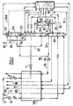
- feed air 1 substantially free of moisture and CO2 is divided into three streams 3,17,50 each of which are cooled in the main exchanger 100.
- Air stream 3 is compressed in a booster 5 before cooling, traverses heat exchanger 100,is expanded in a valve (or a liquid turbine) and fed to a high pressure column 101 in liquid form.
- Stream 17 is cools in heat exchanger 100 and is fed to the high pressure column 101 in gaseous form.
- Stream 50 is compressed in a booster 6 and partially cooled in heat exchanger 100 before being expanded in turbine 7 and sent to the low pressure column 103.
- refrigeration could be provided by a Claude turbine sending air to the high pressure column or a turbine expanding gas from one or several of the columns 101,102,103.
- First oxygen enriched stream 10 extracted from column 101 is subcooled in subcooler 83, expanded and sent to an intermediate level of intermediate pressure column 102 wherein it is separated into a second oxygen enriched stream 20 and a second nitrogen enriched stream at the top.
- a portion of the second nitrogen enriched stream is extracted as liquid reflux 25 and sent to the top of the low pressure column.
- all or part of this stream may be sent to the top condenser 27 of argon column 104 as shown in dashed line 25A.
- a portion 9 of a first nitrogen enriched gas from the high pressure column 101 is sent to the bottom reboiler 11 of the intermediate pressure column 102, condensed and sent back to the high pressure column as reflux.
- Other heating fluids such as gas from lower down the high pressure column could be envisaged.
- Part of the first nitrogen enriched gas from the high pressure column 101 is used to heat the bottom reboiler 8 of the low pressure column.
- Part of the second oxygen enriched stream 20 is sent to the low pressure column following expansion and the rest is sent to the top condenser 13 of the intermediate pressure column 102 where it vaporizes at least partially and is sent to the low pressure column 103 a few trays below the other part of stream 20.
- a nitrogen enriched stream 15 is removed below stream 9or from the same level as stream 9,expanded and sent to the low pressure column. In this case no nitrogen enriched liquid is sent from the high pressure column to the intermediate pressure column.
- the low pressure column 103 separates its feeds into a third oxygen rich stream 31 containing at least 95% oxygen at the bottom and a third nitrogen rich stream at the top. Liquid stream 31 is pumped in pump 19 and sent to the heat exchanger 100 where it vaporizes to form gaseous oxygen product.
- the liquid oxygen may of course be vaporized in a distinct product vaporizer by heat exchange with air or nitrogen only.
- the intermediate pressure column is operated at a pressure lower than the high pressure column pressure but higher than the low pressure column pressure.
- a first argon enriched liquid stream 33 containing between 3 and 12mol% argon is extracted above the bottom stream 31.
- Stream 33 comprising principally oxygen and argon is expanded in a valve and fed in liquid form to an intermediate level of the argon column 104 wherein it is separated into a argon stream 80 at the top and a fourth oxygen enriched stream 36 at the bottom.
- the argon column is fed only by a liquid stream with a gaseous content of at most 2%.
- Liquid stream 36 is pumped to the pressure of stream 31 and mixed therewith.
- the argon column operates at a lower pressure than the low pressure column and is reboiled by nitrogen rich stream 70, containing at least 95mol% nitrogen and preferably at least 98mol % nitrogen, from the top of the low pressure column sent to bottom reboiler 23 and then returned to the top of low pressure column 103.
- the argon is but if necessary additional trays could be used in the argon column to produce high purity argon (99.9999%).
- the top condenser 27 of the argon column is cooled using expanded nitrogen enriched liquid 81 from the top of the low pressure column 103 containing at least 95% nitrogen and preferably at least 98mol % nitrogen.
- This liquid may be supplemented or replaced by stream 25A containing at least 95mol % nitrogen and preferably 98% nitrogen from the intermediate pressure column 102.
- Another alternative technique is sending the nitrogen enriched gas from the top of the low pressure column to the bottom reboiler of the argon column wherein it is condensed to form a nitrogen enriched liquid. At least a portion of this nitrogen enriched liquid can be sent to the condenser of the argon column wherein it is vaporized by exchanging heat with the top gas of the column to provide the needed refluxing action.
- the vaporized liquid is warmed in subcooler 83 and then in heat exchanger 100 to form low pressure nitrogen 85.
- Nitrogen enriched gas from the top of the low pressure column is also warmed in exchangers 83,100 to form medium pressure nitrogen 72.
- High pressure nitrogen 93 is removed from the high pressure column and sent to heat exchanger 100.
- liquid nitrogen may be removed from one of the columns, pumped and vaporized in the heat exchanger 100.
- Liquid argon may be removed from the argon column 104.
- Liquids may also be produced as final products.
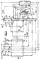
- the embodiment of Figure 2 differs from that of Figure 1 in that the reboil of the argon column 104 is achieved by further compressing a part of stream 85 (or nitrogen gas from the low pressure column) in compressor 81 at ambient temperature, cooling the compressed stream in exchanger 100 and condensing this recycle stream at the bottom reboiler 23 of the argon column.
- Stream 85 contains at least 90% nitrogen.
- the condensed liquid is fed to the top of the low pressure column 103. This situation applies when the feed air pressure is low resulting in lower pressure in the low pressure column such that it is no longer possible to reboil the argon column with the nitrogen rich gas at the top of the low pressure column.
- Figure 3 differs from that of figure 2 in that instead of recovering the fourth oxygen rich stream 36 as product this stream is pumped and recycled back to the low pressure column for further distillation at the same level as the withdrawal point of stream 33.
- the first argon enriched stream 33 is sent to the bottom of the argon column 104.
- the low purity oxygen stream can be extracted directly from stream 33 or at the low pressure column 103 in the vicinity of the tray where stream 33 is extracted. This configuration allows to optimize the power consumption in function of the quantity of the pure oxygen produced.
- argon is not needed one can reduce the number of theoretical trays of the argon column above the feed point of stream 33. In this situation the argon stream still contains significant concentration of oxygen (for example 50% argon and 50% oxygen), and may be discarded, used to cool the feed air or sent back to the low pressure column.
- oxygen for example 50% argon and 50% oxygen
- the number of trays in the low pressure column can be arranged to provide an oxygen-argon feed stream to the argon column containing less than 3ppm, preferably less than 1ppm nitrogen.
- the argon product will therefore not contain nitrogen (ppm range) and another column is not needed for nitrogen removal. If sufficient number of trays are installed in the argon column the argon stream can be distilled to ppm levels of oxygen content such that the final argon product can be produced directly from the argon column.
- This column can be of single or multiple sections with liquid transfer pumps in between sections.
- the high pressure, low pressure and argon columns form a single structure with the intermediate pressure column as a side column. It will be appreciated that the columns could be arranged differently, for example the high pressure and low pressure columns could be positioned side by side, the intermediate pressure column could form a single structure with the high and/or low pressure column etc. By the same token, the argon column can be placed side by side with the low pressure column rather that above it.
- Condensing liquid nitrogen from the bottom reboiler of the argon column may be transferred back to the low pressure column by pumping for example or to the condenser of the argon column without pumping.
- the versions illustrated show the use of nitrogen enriched gas from the high pressure column to reboil the low pressure column.
- air or another gas from one of the columns could be used to reboil the low pressure column if another reboiler is provided for condensing the nitrogen enriched gas against a liquid from further up the low pressure column.
- the high pressure column may operate at between 10 and 20 bar, the intermediate pressure column at between 6 and 13 bar, the low pressure column at between 3 and 7 bar and the argon column at between 1.1 and 2.5 bar.
- All or some of the columns may contain structured packing of the cross corrugated type or of the Werlen/Lehman type described in EP-A-0845293.
- Air may be supplied to the high pressure column or another column of the apparatus from the compressor of a gas turbine, possibly after a further compression step.
Landscapes
- Engineering & Computer Science (AREA)
- Physics & Mathematics (AREA)
- Mechanical Engineering (AREA)
- Thermal Sciences (AREA)
- General Engineering & Computer Science (AREA)
- Health & Medical Sciences (AREA)
- Emergency Medicine (AREA)
- Separation By Low-Temperature Treatments (AREA)
- Organic Low-Molecular-Weight Compounds And Preparation Thereof (AREA)
Applications Claiming Priority (2)
| Application Number | Priority Date | Filing Date | Title |
|---|---|---|---|
| US09/317,958 US6347534B1 (en) | 1999-05-25 | 1999-05-25 | Cryogenic distillation system for air separation |
| US317958 | 1999-05-25 |
Publications (2)
| Publication Number | Publication Date |
|---|---|
| EP1055890A1 true EP1055890A1 (de) | 2000-11-29 |
| EP1055890B1 EP1055890B1 (de) | 2004-02-25 |
Family
ID=23235998
Family Applications (1)
| Application Number | Title | Priority Date | Filing Date |
|---|---|---|---|
| EP00201765A Expired - Lifetime EP1055890B1 (de) | 1999-05-25 | 2000-05-19 | Tieftemperaturdestillationsanlage zur Luftzerleggung |
Country Status (9)
| Country | Link |
|---|---|
| US (1) | US6347534B1 (de) |
| EP (1) | EP1055890B1 (de) |
| JP (1) | JP2000356464A (de) |
| KR (1) | KR100790911B1 (de) |
| AT (1) | ATE260452T1 (de) |
| CA (1) | CA2308812C (de) |
| DE (1) | DE60008455T2 (de) |
| ES (1) | ES2218062T3 (de) |
| ZA (1) | ZA200002399B (de) |
Cited By (1)
| Publication number | Priority date | Publication date | Assignee | Title |
|---|---|---|---|---|
| CN102564063A (zh) * | 2010-11-09 | 2012-07-11 | 林德股份公司 | 低温分离空气的方法和设备 |
Families Citing this family (11)
| Publication number | Priority date | Publication date | Assignee | Title |
|---|---|---|---|---|
| FR2814229B1 (fr) * | 2000-09-19 | 2002-10-25 | Air Liquide | Procede et installation de separation d'air par distillation cryogenique |
| EP1318367B2 (de) * | 2001-12-04 | 2009-11-11 | Air Products And Chemicals, Inc. | Verfahren und Vorrichtung zur kryogenischen Luftzerlegung |
| PL372916A1 (en) * | 2002-04-11 | 2005-08-08 | Richard A. Haase | Water combustion technology-methods, processes, systems and apparatus for the combustion of hydrogen and oxygen |
| WO2007057730A1 (en) * | 2005-11-17 | 2007-05-24 | L'air Liquide, Societe Anonyme Pour L'etude Et L'exploitation Des Procedes Georges Claude | Process and apparatus for the separation of air by cryogenic distillation |
| US7437890B2 (en) * | 2006-01-12 | 2008-10-21 | Praxair Technology, Inc. | Cryogenic air separation system with multi-pressure air liquefaction |
| US8268269B2 (en) * | 2006-01-24 | 2012-09-18 | Clearvalue Technologies, Inc. | Manufacture of water chemistries |
| US9726427B1 (en) * | 2010-05-19 | 2017-08-08 | Cosmodyne, LLC | Liquid nitrogen production |
| KR102178230B1 (ko) * | 2013-03-06 | 2020-11-12 | 린데 악티엔게젤샤프트 | 공기 분리 플랜트, 아르곤을 함유하는 생성물을 수득하는 방법 및 공기 분리 플랜트를 형성하는 방법 |
| JP6092804B2 (ja) * | 2014-03-24 | 2017-03-08 | 大陽日酸株式会社 | 空気液化分離方法及び装置 |
| EP3067650B1 (de) * | 2015-03-13 | 2018-04-25 | Linde Aktiengesellschaft | Anlage und verfahren zur erzeugung von sauerstoff durch tieftemperaturzerlegung von luft |
| JP7378695B2 (ja) * | 2020-01-06 | 2023-11-14 | 日本エア・リキード合同会社 | 空気分離システム |
Citations (4)
| Publication number | Priority date | Publication date | Assignee | Title |
|---|---|---|---|---|
| US1880981A (en) * | 1930-02-07 | 1932-10-04 | Pollitzer Franz | Separation of oxygen, nitrogen, and argon from air |
| EP0286314A1 (de) * | 1987-04-07 | 1988-10-12 | The BOC Group plc | Lufttrennung |
| EP0694745A1 (de) * | 1994-07-25 | 1996-01-31 | The BOC Group plc | Lufttrennung |
| US5644934A (en) * | 1994-12-05 | 1997-07-08 | Linde Aktiengesellchaft | Process and device for low-temperature separation of air |
Family Cites Families (23)
| Publication number | Priority date | Publication date | Assignee | Title |
|---|---|---|---|---|
| US4433989A (en) | 1982-09-13 | 1984-02-28 | Erickson Donald C | Air separation with medium pressure enrichment |
| DE3840506A1 (de) * | 1988-12-01 | 1990-06-07 | Linde Ag | Verfahren und vorrichtung zur luftzerlegung |
| US5049173A (en) * | 1990-03-06 | 1991-09-17 | Air Products And Chemicals, Inc. | Production of ultra-high purity oxygen from cryogenic air separation plants |
| US5224045A (en) | 1990-11-27 | 1993-06-29 | Navistar International Transportation Corp. | Automotive vehicle microprocessor control having grade-holder vehicle speed control |
| DE4126945A1 (de) * | 1991-08-14 | 1993-02-18 | Linde Ag | Verfahren zur luftzerlegung durch rektifikation |
| US5231837A (en) | 1991-10-15 | 1993-08-03 | Liquid Air Engineering Corporation | Cryogenic distillation process for the production of oxygen and nitrogen |
| US5257504A (en) | 1992-02-18 | 1993-11-02 | Air Products And Chemicals, Inc. | Multiple reboiler, double column, elevated pressure air separation cycles and their integration with gas turbines |
| US5245832A (en) | 1992-04-20 | 1993-09-21 | Praxair Technology, Inc. | Triple column cryogenic rectification system |
| GB9213776D0 (en) | 1992-06-29 | 1992-08-12 | Boc Group Plc | Air separation |
| US5282365A (en) * | 1992-11-17 | 1994-02-01 | Praxair Technology, Inc. | Packed column distillation system |
| DE69419675T2 (de) | 1993-04-30 | 2000-04-06 | Boc Group Plc | Lufttrennung |
| GB9405071D0 (en) | 1993-07-05 | 1994-04-27 | Boc Group Plc | Air separation |
| US5341646A (en) | 1993-07-15 | 1994-08-30 | Air Products And Chemicals, Inc. | Triple column distillation system for oxygen and pressurized nitrogen production |
| GB9410696D0 (en) | 1994-05-27 | 1994-07-13 | Boc Group Plc | Air separation |
| US5692395A (en) | 1995-01-20 | 1997-12-02 | Agrawal; Rakesh | Separation of fluid mixtures in multiple distillation columns |
| US5513497A (en) | 1995-01-20 | 1996-05-07 | Air Products And Chemicals, Inc. | Separation of fluid mixtures in multiple distillation columns |
| US5678426A (en) | 1995-01-20 | 1997-10-21 | Air Products And Chemicals, Inc. | Separation of fluid mixtures in multiple distillation columns |
| US5666823A (en) | 1996-01-31 | 1997-09-16 | Air Products And Chemicals, Inc. | High pressure combustion turbine and air separation system integration |
| US5582033A (en) * | 1996-03-21 | 1996-12-10 | Praxair Technology, Inc. | Cryogenic rectification system for producing nitrogen having a low argon content |
| GB9619718D0 (en) | 1996-09-20 | 1996-11-06 | Boc Group Plc | Air separation |
| US5682764A (en) | 1996-10-25 | 1997-11-04 | Air Products And Chemicals, Inc. | Three column cryogenic cycle for the production of impure oxygen and pure nitrogen |
| US5675977A (en) | 1996-11-07 | 1997-10-14 | Praxair Technology, Inc. | Cryogenic rectification system with kettle liquid column |
| US5768914A (en) * | 1997-07-28 | 1998-06-23 | Air Products And Chemicals, Inc. | Process to produce oxygen and argon using divided argon column |
-
1999
- 1999-05-25 US US09/317,958 patent/US6347534B1/en not_active Expired - Fee Related
-
2000
- 2000-05-15 CA CA002308812A patent/CA2308812C/en not_active Expired - Fee Related
- 2000-05-16 ZA ZA200002399A patent/ZA200002399B/xx unknown
- 2000-05-19 DE DE60008455T patent/DE60008455T2/de not_active Expired - Fee Related
- 2000-05-19 AT AT00201765T patent/ATE260452T1/de not_active IP Right Cessation
- 2000-05-19 ES ES00201765T patent/ES2218062T3/es not_active Expired - Lifetime
- 2000-05-19 EP EP00201765A patent/EP1055890B1/de not_active Expired - Lifetime
- 2000-05-23 JP JP2000151607A patent/JP2000356464A/ja not_active Withdrawn
- 2000-05-24 KR KR1020000027927A patent/KR100790911B1/ko not_active IP Right Cessation
Patent Citations (4)
| Publication number | Priority date | Publication date | Assignee | Title |
|---|---|---|---|---|
| US1880981A (en) * | 1930-02-07 | 1932-10-04 | Pollitzer Franz | Separation of oxygen, nitrogen, and argon from air |
| EP0286314A1 (de) * | 1987-04-07 | 1988-10-12 | The BOC Group plc | Lufttrennung |
| EP0694745A1 (de) * | 1994-07-25 | 1996-01-31 | The BOC Group plc | Lufttrennung |
| US5644934A (en) * | 1994-12-05 | 1997-07-08 | Linde Aktiengesellchaft | Process and device for low-temperature separation of air |
Cited By (1)
| Publication number | Priority date | Publication date | Assignee | Title |
|---|---|---|---|---|
| CN102564063A (zh) * | 2010-11-09 | 2012-07-11 | 林德股份公司 | 低温分离空气的方法和设备 |
Also Published As
| Publication number | Publication date |
|---|---|
| DE60008455D1 (de) | 2004-04-01 |
| CA2308812A1 (en) | 2000-11-25 |
| DE60008455T2 (de) | 2004-12-02 |
| KR100790911B1 (ko) | 2008-01-03 |
| CA2308812C (en) | 2008-08-26 |
| ATE260452T1 (de) | 2004-03-15 |
| ZA200002399B (en) | 2000-11-16 |
| EP1055890B1 (de) | 2004-02-25 |
| ES2218062T3 (es) | 2004-11-16 |
| US6347534B1 (en) | 2002-02-19 |
| KR20010049392A (ko) | 2001-06-15 |
| JP2000356464A (ja) | 2000-12-26 |
Similar Documents
| Publication | Publication Date | Title |
|---|---|---|
| US4578095A (en) | Low energy high purity oxygen plus argon | |
| EP1134526B1 (de) | Verfahren zur Herstellung von Sauerstoff und Stickstoff | |
| EP0793069A1 (de) | Mit einem Aufkochkompressor versehener Generator für Sauerstoff von zwei Reinheitsgraden | |
| EP0860670A2 (de) | Lufttrennung mit Verdampfung und Expansion eines Fluidiums unter mittlerem Druck | |
| US20060075779A1 (en) | Process for the cryogenic distillation of air | |
| EP1055890B1 (de) | Tieftemperaturdestillationsanlage zur Luftzerleggung | |
| US6202441B1 (en) | Cryogenic distillation system for air separation | |
| EP1055892B1 (de) | Tieftemperaturrektifikationsystem zur Luftzerleggung | |
| EP0823606B1 (de) | Verfahren zur Herstellung von Stickstoff unter Verwendung einer Doppelkolonne und einer Niederdruckabtrennungszone | |
| EP1055893B1 (de) | Tieftemperaturdestilationsanlage zur Luftzerlegung | |
| EP0834712A2 (de) | Verfahren zur Herstellung von Hochdruck-Stickstoff mit Hilfe einer Kolonne unter höherem Druck und ein oder mehrere Kolonnen unter niedrigerem Druck | |
| EP0877219A2 (de) | Verfahren zur Herstellung von Stickstoff unter Verwendung einer Doppeltkolonne und drei Verdampfer-Kondensoren | |
| US6318120B1 (en) | Cryogenic distillation system for air separation | |
| EP0848219A2 (de) | Kryogenisches Rektifikationssystem zur Herstellung von Argon und Sauerstoff niedriger Reinheit | |
| US6339938B1 (en) | Apparatus and process for separating air by cryogenic distillation | |
| EP1271080A1 (de) | Erzeugung von Stickstoff mittleren Druckes mit hoher Sauerstoffausbeute | |
| EP0770840A2 (de) | Lufttrennung |
Legal Events
| Date | Code | Title | Description |
|---|---|---|---|
| PUAI | Public reference made under article 153(3) epc to a published international application that has entered the european phase |
Free format text: ORIGINAL CODE: 0009012 |
|
| AK | Designated contracting states |
Kind code of ref document: A1 Designated state(s): AT BE CH CY DE DK ES FI FR GB GR IE IT LI LU MC NL PT SE |
|
| AX | Request for extension of the european patent |
Free format text: AL;LT;LV;MK;RO;SI |
|
| 17P | Request for examination filed |
Effective date: 20010529 |
|
| AKX | Designation fees paid |
Free format text: AT BE CH CY DE DK ES FI FR GB GR IE IT LI LU MC NL PT SE |
|
| RAP1 | Party data changed (applicant data changed or rights of an application transferred) |
Owner name: L'AIR LIQUIDE, S.A. A DIRECTOIRE ET CONSEIL DE SUR |
|
| 17Q | First examination report despatched |
Effective date: 20030121 |
|
| GRAP | Despatch of communication of intention to grant a patent |
Free format text: ORIGINAL CODE: EPIDOSNIGR1 |
|
| GRAS | Grant fee paid |
Free format text: ORIGINAL CODE: EPIDOSNIGR3 |
|
| GRAA | (expected) grant |
Free format text: ORIGINAL CODE: 0009210 |
|
| AK | Designated contracting states |
Kind code of ref document: B1 Designated state(s): AT BE CH CY DE DK ES FI FR GB GR IE IT LI LU MC NL PT SE |
|
| PG25 | Lapsed in a contracting state [announced via postgrant information from national office to epo] |
Ref country code: LI Free format text: LAPSE BECAUSE OF FAILURE TO SUBMIT A TRANSLATION OF THE DESCRIPTION OR TO PAY THE FEE WITHIN THE PRESCRIBED TIME-LIMIT Effective date: 20040225 Ref country code: CH Free format text: LAPSE BECAUSE OF FAILURE TO SUBMIT A TRANSLATION OF THE DESCRIPTION OR TO PAY THE FEE WITHIN THE PRESCRIBED TIME-LIMIT Effective date: 20040225 Ref country code: AT Free format text: LAPSE BECAUSE OF FAILURE TO SUBMIT A TRANSLATION OF THE DESCRIPTION OR TO PAY THE FEE WITHIN THE PRESCRIBED TIME-LIMIT Effective date: 20040225 Ref country code: CY Free format text: LAPSE BECAUSE OF FAILURE TO SUBMIT A TRANSLATION OF THE DESCRIPTION OR TO PAY THE FEE WITHIN THE PRESCRIBED TIME-LIMIT Effective date: 20040225 Ref country code: FI Free format text: LAPSE BECAUSE OF FAILURE TO SUBMIT A TRANSLATION OF THE DESCRIPTION OR TO PAY THE FEE WITHIN THE PRESCRIBED TIME-LIMIT Effective date: 20040225 |
|
| REG | Reference to a national code |
Ref country code: GB Ref legal event code: FG4D |
|
| REG | Reference to a national code |
Ref country code: CH Ref legal event code: EP |
|
| REG | Reference to a national code |
Ref country code: IE Ref legal event code: FG4D |
|
| REF | Corresponds to: |
Ref document number: 60008455 Country of ref document: DE Date of ref document: 20040401 Kind code of ref document: P |
|
| PG25 | Lapsed in a contracting state [announced via postgrant information from national office to epo] |
Ref country code: IE Free format text: LAPSE BECAUSE OF NON-PAYMENT OF DUE FEES Effective date: 20040519 Ref country code: LU Free format text: LAPSE BECAUSE OF NON-PAYMENT OF DUE FEES Effective date: 20040519 |
|
| PG25 | Lapsed in a contracting state [announced via postgrant information from national office to epo] |
Ref country code: SE Free format text: LAPSE BECAUSE OF FAILURE TO SUBMIT A TRANSLATION OF THE DESCRIPTION OR TO PAY THE FEE WITHIN THE PRESCRIBED TIME-LIMIT Effective date: 20040525 Ref country code: DK Free format text: LAPSE BECAUSE OF FAILURE TO SUBMIT A TRANSLATION OF THE DESCRIPTION OR TO PAY THE FEE WITHIN THE PRESCRIBED TIME-LIMIT Effective date: 20040525 Ref country code: GR Free format text: LAPSE BECAUSE OF FAILURE TO SUBMIT A TRANSLATION OF THE DESCRIPTION OR TO PAY THE FEE WITHIN THE PRESCRIBED TIME-LIMIT Effective date: 20040525 |
|
| PG25 | Lapsed in a contracting state [announced via postgrant information from national office to epo] |
Ref country code: MC Free format text: LAPSE BECAUSE OF NON-PAYMENT OF DUE FEES Effective date: 20040531 |
|
| REG | Reference to a national code |
Ref country code: CH Ref legal event code: PL |
|
| REG | Reference to a national code |
Ref country code: ES Ref legal event code: FG2A Ref document number: 2218062 Country of ref document: ES Kind code of ref document: T3 |
|
| ET | Fr: translation filed | ||
| PLBE | No opposition filed within time limit |
Free format text: ORIGINAL CODE: 0009261 |
|
| STAA | Information on the status of an ep patent application or granted ep patent |
Free format text: STATUS: NO OPPOSITION FILED WITHIN TIME LIMIT |
|
| 26N | No opposition filed |
Effective date: 20041126 |
|
| REG | Reference to a national code |
Ref country code: IE Ref legal event code: MM4A |
|
| PG25 | Lapsed in a contracting state [announced via postgrant information from national office to epo] |
Ref country code: PT Free format text: LAPSE BECAUSE OF NON-PAYMENT OF DUE FEES Effective date: 20040725 |
|
| PGFP | Annual fee paid to national office [announced via postgrant information from national office to epo] |
Ref country code: DE Payment date: 20080425 Year of fee payment: 9 Ref country code: ES Payment date: 20080512 Year of fee payment: 9 |
|
| PGFP | Annual fee paid to national office [announced via postgrant information from national office to epo] |
Ref country code: BE Payment date: 20080506 Year of fee payment: 9 Ref country code: IT Payment date: 20080423 Year of fee payment: 9 |
|
| PGFP | Annual fee paid to national office [announced via postgrant information from national office to epo] |
Ref country code: NL Payment date: 20080418 Year of fee payment: 9 |
|
| PGFP | Annual fee paid to national office [announced via postgrant information from national office to epo] |
Ref country code: FR Payment date: 20080414 Year of fee payment: 9 |
|
| PGFP | Annual fee paid to national office [announced via postgrant information from national office to epo] |
Ref country code: GB Payment date: 20080425 Year of fee payment: 9 |
|
| BERE | Be: lapsed |
Owner name: S.A. L'*AIR LIQUIDE A DIRECTOIRE ET CONSEIL DE SUR Effective date: 20090531 |
|
| GBPC | Gb: european patent ceased through non-payment of renewal fee |
Effective date: 20090519 |
|
| NLV4 | Nl: lapsed or anulled due to non-payment of the annual fee |
Effective date: 20091201 |
|
| PG25 | Lapsed in a contracting state [announced via postgrant information from national office to epo] |
Ref country code: NL Free format text: LAPSE BECAUSE OF NON-PAYMENT OF DUE FEES Effective date: 20091201 |
|
| REG | Reference to a national code |
Ref country code: FR Ref legal event code: ST Effective date: 20100129 |
|
| PG25 | Lapsed in a contracting state [announced via postgrant information from national office to epo] |
Ref country code: FR Free format text: LAPSE BECAUSE OF NON-PAYMENT OF DUE FEES Effective date: 20090602 |
|
| PG25 | Lapsed in a contracting state [announced via postgrant information from national office to epo] |
Ref country code: GB Free format text: LAPSE BECAUSE OF NON-PAYMENT OF DUE FEES Effective date: 20090519 |
|
| PG25 | Lapsed in a contracting state [announced via postgrant information from national office to epo] |
Ref country code: BE Free format text: LAPSE BECAUSE OF NON-PAYMENT OF DUE FEES Effective date: 20090531 Ref country code: DE Free format text: LAPSE BECAUSE OF NON-PAYMENT OF DUE FEES Effective date: 20091201 |
|
| REG | Reference to a national code |
Ref country code: ES Ref legal event code: FD2A Effective date: 20090520 |
|
| PG25 | Lapsed in a contracting state [announced via postgrant information from national office to epo] |
Ref country code: ES Free format text: LAPSE BECAUSE OF NON-PAYMENT OF DUE FEES Effective date: 20090520 |
|
| PG25 | Lapsed in a contracting state [announced via postgrant information from national office to epo] |
Ref country code: IT Free format text: LAPSE BECAUSE OF NON-PAYMENT OF DUE FEES Effective date: 20090519 |