EP1055834A1 - Linearführungsvorrichtung und übertragungstafel - Google Patents
Linearführungsvorrichtung und übertragungstafel Download PDFInfo
- Publication number
- EP1055834A1 EP1055834A1 EP98953074A EP98953074A EP1055834A1 EP 1055834 A1 EP1055834 A1 EP 1055834A1 EP 98953074 A EP98953074 A EP 98953074A EP 98953074 A EP98953074 A EP 98953074A EP 1055834 A1 EP1055834 A1 EP 1055834A1
- Authority
- EP
- European Patent Office
- Prior art keywords
- ball
- loaded
- groove
- grooves
- running
- Prior art date
- Legal status (The legal status is an assumption and is not a legal conclusion. Google has not performed a legal analysis and makes no representation as to the accuracy of the status listed.)
- Withdrawn
Links
Images


Classifications
-
- F—MECHANICAL ENGINEERING; LIGHTING; HEATING; WEAPONS; BLASTING
- F16—ENGINEERING ELEMENTS AND UNITS; GENERAL MEASURES FOR PRODUCING AND MAINTAINING EFFECTIVE FUNCTIONING OF MACHINES OR INSTALLATIONS; THERMAL INSULATION IN GENERAL
- F16C—SHAFTS; FLEXIBLE SHAFTS; ELEMENTS OR CRANKSHAFT MECHANISMS; ROTARY BODIES OTHER THAN GEARING ELEMENTS; BEARINGS
- F16C29/00—Bearings for parts moving only linearly
- F16C29/04—Ball or roller bearings
- F16C29/06—Ball or roller bearings in which the rolling bodies circulate partly without carrying load
- F16C29/0633—Ball or roller bearings in which the rolling bodies circulate partly without carrying load with a bearing body defining a U-shaped carriage, i.e. surrounding a guide rail or track on three sides
- F16C29/0652—Ball or roller bearings in which the rolling bodies circulate partly without carrying load with a bearing body defining a U-shaped carriage, i.e. surrounding a guide rail or track on three sides whereby the return paths are at least partly defined by separate parts, e.g. covers attached to the legs of the main body of the U-shaped carriage
- F16C29/0654—Ball or roller bearings in which the rolling bodies circulate partly without carrying load with a bearing body defining a U-shaped carriage, i.e. surrounding a guide rail or track on three sides whereby the return paths are at least partly defined by separate parts, e.g. covers attached to the legs of the main body of the U-shaped carriage with balls
- F16C29/0657—Ball or roller bearings in which the rolling bodies circulate partly without carrying load with a bearing body defining a U-shaped carriage, i.e. surrounding a guide rail or track on three sides whereby the return paths are at least partly defined by separate parts, e.g. covers attached to the legs of the main body of the U-shaped carriage with balls with two rows of balls, one on each side of the rail
-
- F—MECHANICAL ENGINEERING; LIGHTING; HEATING; WEAPONS; BLASTING
- F16—ENGINEERING ELEMENTS AND UNITS; GENERAL MEASURES FOR PRODUCING AND MAINTAINING EFFECTIVE FUNCTIONING OF MACHINES OR INSTALLATIONS; THERMAL INSULATION IN GENERAL
- F16C—SHAFTS; FLEXIBLE SHAFTS; ELEMENTS OR CRANKSHAFT MECHANISMS; ROTARY BODIES OTHER THAN GEARING ELEMENTS; BEARINGS
- F16C29/00—Bearings for parts moving only linearly
- F16C29/04—Ball or roller bearings
-
- B—PERFORMING OPERATIONS; TRANSPORTING
- B23—MACHINE TOOLS; METAL-WORKING NOT OTHERWISE PROVIDED FOR
- B23Q—DETAILS, COMPONENTS, OR ACCESSORIES FOR MACHINE TOOLS, e.g. ARRANGEMENTS FOR COPYING OR CONTROLLING; MACHINE TOOLS IN GENERAL CHARACTERISED BY THE CONSTRUCTION OF PARTICULAR DETAILS OR COMPONENTS; COMBINATIONS OR ASSOCIATIONS OF METAL-WORKING MACHINES, NOT DIRECTED TO A PARTICULAR RESULT
- B23Q1/00—Members which are comprised in the general build-up of a form of machine, particularly relatively large fixed members
- B23Q1/25—Movable or adjustable work or tool supports
- B23Q1/26—Movable or adjustable work or tool supports characterised by constructional features relating to the co-operation of relatively movable members; Means for preventing relative movement of such members
- B23Q1/40—Movable or adjustable work or tool supports characterised by constructional features relating to the co-operation of relatively movable members; Means for preventing relative movement of such members using ball, roller or wheel arrangements
-
- B—PERFORMING OPERATIONS; TRANSPORTING
- B23—MACHINE TOOLS; METAL-WORKING NOT OTHERWISE PROVIDED FOR
- B23Q—DETAILS, COMPONENTS, OR ACCESSORIES FOR MACHINE TOOLS, e.g. ARRANGEMENTS FOR COPYING OR CONTROLLING; MACHINE TOOLS IN GENERAL CHARACTERISED BY THE CONSTRUCTION OF PARTICULAR DETAILS OR COMPONENTS; COMBINATIONS OR ASSOCIATIONS OF METAL-WORKING MACHINES, NOT DIRECTED TO A PARTICULAR RESULT
- B23Q1/00—Members which are comprised in the general build-up of a form of machine, particularly relatively large fixed members
- B23Q1/25—Movable or adjustable work or tool supports
- B23Q1/44—Movable or adjustable work or tool supports using particular mechanisms
- B23Q1/56—Movable or adjustable work or tool supports using particular mechanisms with sliding pairs only, the sliding pairs being the first two elements of the mechanism
- B23Q1/58—Movable or adjustable work or tool supports using particular mechanisms with sliding pairs only, the sliding pairs being the first two elements of the mechanism a single sliding pair
-
- F—MECHANICAL ENGINEERING; LIGHTING; HEATING; WEAPONS; BLASTING
- F16—ENGINEERING ELEMENTS AND UNITS; GENERAL MEASURES FOR PRODUCING AND MAINTAINING EFFECTIVE FUNCTIONING OF MACHINES OR INSTALLATIONS; THERMAL INSULATION IN GENERAL
- F16C—SHAFTS; FLEXIBLE SHAFTS; ELEMENTS OR CRANKSHAFT MECHANISMS; ROTARY BODIES OTHER THAN GEARING ELEMENTS; BEARINGS
- F16C29/00—Bearings for parts moving only linearly
- F16C29/008—Systems with a plurality of bearings, e.g. four carriages supporting a slide on two parallel rails
-
- F—MECHANICAL ENGINEERING; LIGHTING; HEATING; WEAPONS; BLASTING
- F16—ENGINEERING ELEMENTS AND UNITS; GENERAL MEASURES FOR PRODUCING AND MAINTAINING EFFECTIVE FUNCTIONING OF MACHINES OR INSTALLATIONS; THERMAL INSULATION IN GENERAL
- F16C—SHAFTS; FLEXIBLE SHAFTS; ELEMENTS OR CRANKSHAFT MECHANISMS; ROTARY BODIES OTHER THAN GEARING ELEMENTS; BEARINGS
- F16C29/00—Bearings for parts moving only linearly
- F16C29/04—Ball or roller bearings
- F16C29/06—Ball or roller bearings in which the rolling bodies circulate partly without carrying load
- F16C29/0602—Details of the bearing body or carriage or parts thereof, e.g. methods for manufacturing or assembly
- F16C29/0604—Details of the bearing body or carriage or parts thereof, e.g. methods for manufacturing or assembly of the load bearing section
- F16C29/0607—Details of the bearing body or carriage or parts thereof, e.g. methods for manufacturing or assembly of the load bearing section of parts or members for retaining the rolling elements, i.e. members to prevent the rolling elements from falling out of the bearing body or carriage
-
- F—MECHANICAL ENGINEERING; LIGHTING; HEATING; WEAPONS; BLASTING
- F16—ENGINEERING ELEMENTS AND UNITS; GENERAL MEASURES FOR PRODUCING AND MAINTAINING EFFECTIVE FUNCTIONING OF MACHINES OR INSTALLATIONS; THERMAL INSULATION IN GENERAL
- F16C—SHAFTS; FLEXIBLE SHAFTS; ELEMENTS OR CRANKSHAFT MECHANISMS; ROTARY BODIES OTHER THAN GEARING ELEMENTS; BEARINGS
- F16C33/00—Parts of bearings; Special methods for making bearings or parts thereof
- F16C33/30—Parts of ball or roller bearings
- F16C33/38—Ball cages
- F16C33/3825—Ball cages formed as a flexible belt, e.g. spacers connected by a thin film
-
- F—MECHANICAL ENGINEERING; LIGHTING; HEATING; WEAPONS; BLASTING
- F16—ENGINEERING ELEMENTS AND UNITS; GENERAL MEASURES FOR PRODUCING AND MAINTAINING EFFECTIVE FUNCTIONING OF MACHINES OR INSTALLATIONS; THERMAL INSULATION IN GENERAL
- F16C—SHAFTS; FLEXIBLE SHAFTS; ELEMENTS OR CRANKSHAFT MECHANISMS; ROTARY BODIES OTHER THAN GEARING ELEMENTS; BEARINGS
- F16C2322/00—Apparatus used in shaping articles
- F16C2322/39—General build up of machine tools, e.g. spindles, slides, actuators
Definitions
- the present invention relates to a linear motion guide apparatus for carrying out the linear motion guide through balls.
- the conventional linear motion guide apparatus is composed of a guide rail and a movable block, which is provided movably on the guide rail through a plurality of balls.
- the movable block has a block body and end plates.
- the block body is provided with loaded-ball running grooves corresponding to loaded-ball running counter-grooves, which are formed on the guide rail and with non-loaded-ball return passages provided in parallel with the loaded-ball running grooves.
- the end plates are provided on the opposite sides of the block body for connecting the loaded-ball running grooves with the ball return passages to form ball direction changing passages for forming endless circulation passages for the balls.
- retainers 102 are placed on the portions of the end surface of the movable block 100, between which the loaded-ball-running groove 101 locates.
- the width of the opening defined by the retainers 102 is designed to be smaller than the diameter of the ball.
- the retainers 102 locate between the opposing surfaces of the movable block and the guide rail, on which the loaded-ball running groove 101 and the loaded-ball running counter-groove 105 are formed, respectively. Consequently, the loaded-ball running groove 101 and the loaded-ball running counter-groove 105 are restricted in their depth by the thickness of the retainer 102, thus leading to relatively small depths of the loaded-ball running groove 101 and the loaded-ball running counter-groove 105.
- An object of the present invention which was made in order to solve the above-mentioned problems of the conventional prior art, is to provide a linear motion guide apparatus, which permits to impart a deep-groove structure to the loaded-ball running grooves, preventing the occurrence of the edge load and to prevent the ball from coming off the loaded-ball running groove even after the guide rail is pulled out of the movable block.
- the linear motion guide apparatus of the present invention comprises:
- the front and rear sides of each of the balls are held by the adjacent two ball-supporting members to prevent the ball from coming off the loaded-ball running groove even after the guide rail is pulled out of the movable block.
- the ball-supporting members locate within the loaded-ball running groove and the loaded-ball running counter-groove so that the ball-supporting members can be made large to the extent that their size is substantially identical with the diameter of the ball, irrespective of the depths of the loaded-ball running groove and the loaded-ball running counter-groove. It is therefore possible to support the balls surely.
- the joint member which locates between the opposing surfaces of the movable block and the guide rail, has no function of directly supporting the ball, with the result that the thickness of the joint member can be decreased. It is therefore possible to bring the opposing surfaces of the movable block and the guide rail into the closer relationship to the joint member having the decreased thickness to increase the depths of the loaded-ball running groove and the loaded-ball running counter-groove as much as possible.
- the increase in depths of the grooves makes it possible to prevent the ball from coming into contact with the edges of the grooves even when the deviation of the contact points of the ball with the grooves in their width direction occurs. There can accordingly be avoided the occurrence of the problem of the edge load, in which stress concentrates in the edges of the grooves. It is therefore possible to extend the range of an area within which the ball can come into contact with the grooves in their width direction, thus permitting selection of an appropriate contact angle within an extended range thereof.
- the fitting length of the ball into the loaded-ball-running groove and the loaded-ball-running counter-groove in their depth direction also increases. Even when there applies the load having a function of shifting parallelly the opposing surfaces of the movable block and the guide rail in opposite directions to each other in the width direction of the grooves, the contact points of the ball with the grooves deviate within an intermediate region between the deepest point of the grooves and the edges thereof, thus making it possible to prevent the ball from coming into contact with the edges of the grooves.
- the linear motion guide apparatus of the present invention may comprise:
- lateral direction load which has a function of urging the support leg portions of the movable block against the opposite side surfaces of the guide rail, applies so as to compress the ball locating between the guide rail and the corresponding loaded-ball running groove of the support leg portions.
- the ball bears the lateral direction load without causing any undesirable movement of the movable block.
- Each of the loaded-ball running grooves and the loaded-ball-running counter-groove may have a shape in its cross section, which approximates a contour of the ball.
- each of the loaded-ball running groove and the loaded-ball running counter-groove in its cross section in the perpendicular direction to the extending direction of the grooves approximates the contour of the ball, it is possible to prevent the unfavorable movement of the ball relative to the grooves.
- the ball chain may have an endless belt structure.
- Each of the loaded-ball running grooves and the loaded-ball running counter-grooves may be formed into a circular arc-groove shape having a single circular arc in a cross-section.
- a circular arc-groove shape permits the ball to move relatively freely in the grooves in their width direction. It is therefore preferable to adopt an increased depth structure of the grooves and an approximation structure of the cross-sectional shape thereof to the contour of the ball as in the present invention.
- Each of the loaded-ball running grooves and the loaded-ball running counter-grooves may be formed into a Gothic arc-groove shape having two circular arcs in a cross-section.
- Such a Gothic arc-groove shape can prevent more effectively the ball from moving in the width direction of the grooves in comparison with the circular arc-groove shape.
- the support of the balls with the use of the ball chain permits, in the same manner as the circular arc-groove shape, to increase the depths of the loaded-ball running grooves and the loaded-ball running counter-grooves as much as possible, thus preventing the occurrence of the edge load.
- Each of any one of a set of the loaded-ball running grooves formed on the movable block and a set of the loaded-ball running counter-grooves formed on the guide rail is formed into the circular arc-groove shape having the single circular arc in the cross-section, and each of another thereof is formed into a Gothic arc-groove shape having two circular arcs in the cross-section.
- the above-mentioned feature achieves a three-point contact structure of the ball.
- Such a structure provides an intermediate characteristic property between a two-point contact structure and a four-point contact structure so that a misalignment compensation property can become more excellent in comparison with the four-point contact structure having a pair of Gothic arc-grooves and rigidity in the swinging direction and the vertical direction can be improved in comparison with the two-point contact structure having a pair of circular arc-grooves.
- Each of the loaded-ball running counter-grooves of the guide rail may be formed into the circular arc-groove shape and each of the corresponding loaded-ball running grooves of the movable block may be formed into the Gothic arc-groove shape.
- Each of the loaded-ball running counter-grooves of the guide rail may be formed into the Gothic arc-groove shape and each of the corresponding loaded-ball running grooves of the movable block may be formed into the circular arc-groove shape.
- the circular arc of the loaded-ball running grooves and the loaded-ball running counter-grooves may have a radius of curvature, which is determined to be within a range of from 50.5 percent to 52.0 percent of the diameter of the ball.
- the circular arc of the grooves of the conventional apparatus is determined to be substantially identical to 52 percent of the diameter of the ball, thus permitting the ball to move relatively freely in the grooves. In view of this fact, it is advisable to limit the circular arc of the grooves to under 52 percent of the diameter of the ball.
- the circular arc of the grooves With an excessively small circular arc of the grooves, a sudden slide of the ball may occur. It is preferable to limit the circular arc of the grooves to at least 50.5 percent of the diameter of the ball in practical use.
- a chain-guide member may be provided on the surface of the movable block, which is in a vicinity of the loaded-ball running groove thereof, the chain-guide member having projections that come into contact with the joint members to prevent the ball chain from coming off the movable block.
- the projections of the chain-guide member can prevent the ball chain from sagging down when the guide rail is pulled out of the movable block. In case where the ball chain has a non-endless belt structure, it is possible to prevent effectively the ball chain from sagging down.
- At least one of the ball return passage and an inner peripheral portion of the ball direction changing passage may be formed of a resin-formed body, which is integrally formed with the block body.
- Such a structure permits a precise formation of the endless circulation passage so as to carry out a smooth guidance of the ball in cooperation with the guidance of ball circulation with the use of the ball chain.
- At least one of the ball return passage, an inner peripheral portion of the ball direction changing passage and the chain-guide member may be formed of a resin-formed body, which is integrally formed with the block body.
- the endless circulation passage can also formed precisely so as to carry out a smooth guidance of the ball in cooperation with the guidance of ball circulation with the use of the ball chain.
- the chain-guide member can also be formed precisely, thus preventing it from coming into contact with the ball chain in an unfavorable manner.
- a table guide apparatus of the present invention comprises:
- the linear motion guide apparatus itself can bear the vertical direction load, the lateral direction load and the moment load, while suppressing play, as mentioned above. Arrangement of the movable blocks of the two sets of the linear motion guide apparatus in an inclined state makes it possible to suppress play effectively in the table guide apparatus.
- Measures to be adopted to incline the movable block may include the formation of the surface of the movable block, onto which the table is mounted, into an inclined surface, the use of a shim locating between the upper surface of the movable block and the lower surface of the table, or any other measures.
- the above-mentioned measures are to incline the both movable blocks in an active manner.
- the guide rails of the two sets of the linear motion guide apparatus are fixed on the stationary bed so as to parallelly spaced apart from each other and the table is mounted on these movable blocks in a usual manner, there exists an inevitable small fitting error.
- the fitting error can be compensated and the movable blocks simultaneously incline, resulting in change in the contact angle.
- the small fitting error causes the contact angle of the ball to vary so as to provide the inclined state of the movable blocks. It is therefore possible to suppress play in the table guide apparatus.
- the four-point contact structure can provide almost no play, but has a low misalignment compensation property.
- the two-point contact structure has a high misalignment compensation property, but provides much play. It is therefore effective to incline the movable blocks having the two-point contact structure in an active manner as mentioned above to suppress the play.
- the three-point contact structure has a middle misalignment compensation property and can provide the play, which is less than that of the two-point contact structure and more than that of the four-point contact structure.
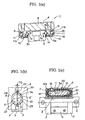
- FIGS. 1 and 2 illustrate a linear motion guide apparatus of the first embodiment of the present invention.
- the linear motion guide apparatus 1 comprises a guide rail 2 and a movable block 4 provided movably on the guide rail 2 through a plurality of balls 3a.
- the guide rail 2 is formed of an elongated member having a square cross-sectional shape.
- the guide rail 2 is designed so as to guide the movable block 4 through two trains of balls each of which is provided on each of opposite sides of the guide rail 2.
- the guide rail 2 is provided on each of the opposite sides thereof with a single loaded-ball running counter-groove 5 extending over the entirety of the guide rail 2 in its longitudinal direction, thus providing the total number of counter-groove of two.
- the loaded-ball running counter-grooves 5, 5 are formed on the opposite vertical side surfaces of the guide rail 2, respectively.
- the movable block 4 is composed of a block body 6 and a pair of end plates 7, which are provided at the opposite ends of the block body 6 so as to serve as a direction changing passage forming member.
- the block body 6 is provided with a horizontal portion 8 facing the upper surface of the guide rail 2 and with a pair of support leg portions 9, 9 facing the opposite side surfaces of the guide rail 2, thus providing a U-shaped cross-section.
- the respective support leg portion 9 has on its inner surface a loaded-ball running groove 10, which corresponds to the respective loaded-ball running counter-groove 5 formed on the opposite side surfaces of the guide rail 2.
- the respective support leg portion 9 has in its inside a ball return passage 11, which is formed into a tunnel-shape so as to extend linearly in parallel with the loaded-ball running groove 10.
- the end plate 7 has a U-shape, which is similar to the cross-section of the block body 6.
- the respective end plates 7, 7 connect the respective loaded-ball running grooves 10, 10 with the respective ball return passage 11, 11 to form ball direction changing passages for forming endless circulation passages for the balls.
- Contact angle lines S1, S2 which connect the contact points of the balls of the two trains of balls with the corresponding loaded-ball running counter-grooves 5, 5 and the corresponding loaded-ball running grooves 10, 10, are designed to be horizontal in principle.
- the two trains 3, 3 of balls are maintained by means of two ball chains 20 so as to circulate in the endless circulation passages.
- Each of the ball chains 20 has ball-supporting members 21 and joint members 22.
- the ball-supporting members 21 locate between the adjacent two balls 3a for forming the train 3 of balls.
- the joint members 22 have flexibility and connect the adjacent two ball-supporting members 21 with each other.
- Each of the joint members 22 is formed into a thin-belt shape.
- the ball chain 20 has its opposite ends, which are not connected to each other, thus forming a non-endless belt structure.
- the ball chain 20 is provided on its front and rear ends with crowning portions 24, respectively.
- the opposite ends of the ball chain 20 may be connected to each other so as to form an endless belt structure.
- Each of the ball supporting members 21 is provided on its opposite ends with spherical supporting recesses 23 for receiving the spherical crown portion of the ball 3a.
- the ball 3a is held between the adjacent two ball supporting members 21 that locate in the front and rear sides of the ball 3a in the running direction thereof.
- the joint member 21 projects toward the adjacent side edge portion of the movable block 4 to the loaded-ball running groove 10 into a gap between the opposing surfaces of the movable block 4 and the guide rail 2.
- a chain-guide member 14 is provided on the adjacent opposite side edge portions of the movable block 4 to the loaded-ball running groove 10 to guide the ball chain 20.
- the chain-guide member 14 has projections 15 that come into contact with the joint members 22 to prevent the ball chain 20 from coming off the movable block 4.
- the ball 3a is held in the supporting recesses 23 of the adjacent ball supporting members 21 of the ball chain 20. Accordingly, it is possible to prevent the balls 3a from coming off the movable block 4 by means of the ball chain 20.
- the ball chain 20 is provided on its front and rear ends with the crowning portions 24, respectively, as mentioned above. The front end of the ball chain 20 is guided into the chain-guide member 14 through the crowing portion 24 so as to perform a circulation motion.
- the crowing portion 24 serves as a member for guiding the ball chain assembly when the assembly is inserted into the groove.
- the joint member 22 locates as shown in FIG. 1(b) so that a point " O' “ locating on the line connecting the central points of the opposite joint members 22 in its thickness direction is shifted from the center "O" of the ball 3a toward the movable block 4 by a prescribed distance, for example, by a distance corresponding to half "t/2" of the thickness "t” of the joint member 22 in accordance with the embodiment as shown in FIG. 1(b).
- the projections 15 of the chain-guide member 14 is shifted from the center "O" of the ball 3a in the opposite direction to the shifting direction of the joint members 22.
- the distance between the deepest point of the loaded-ball running counter-groove 5 and the deepest point of the loaded-ball running groove 10 is substantially identical with the diameter "D" of the ball 3a. It is necessary to decrease the distance "b" between the guide rail 2 and the movable block 4 in order to increase the depths "d" of the loaded-ball running counter-groove 5 and the loaded-ball running groove 10.
- the projection 15 of the chain-guide member 14 is placed on the joint member 22 of the ball chain 20 within the gap corresponding the above-mentioned distance "b". It is therefore suitable to locate the center “O” of the ball 3a in the central point of the total thickness of the projection 15 and the joint member 22. In this embodiment, the projection 15 has substantially the same thickness as that of the joint member 22. Accordingly, the above-mentioned point " O' “ concerning the joint members 22 is shifted from the center "O" of the ball 3a toward the movable block 4 by a distance corresponding to about half of the thickness "t” of the joint member 22
- Each of the loaded-ball-running counter-groove 5 and the loaded-ball-running groove 10 is formed into the circular arc-groove shape having a single circular arc in its cross-section.
- the circular arc preferably has a radius of curvature, which is determined to be within the range of from 50.5 percent to 52.0 percent of the diameter of the ball.
- the respective ball 3a is held at its front and rear sides between the adjacent two ball-supporting members 21. It is therefore possible to prevent the ball 3a from coming off the loaded-ball-running groove, even when the guide rail 2 is pulled out of the movable block 4.
- the ball-supporting members 21 locate within the tunnel-shaped space, which is defined by the loaded-ball running groove 10 and the loaded-ball running counter-groove 5 so that the ball-supporting members 21 can be made large to the extent that their size is substantially identical with the diameter of the ball 3a, irrespective of the depths of the loaded-ball running groove 10 and the loaded-ball running counter-groove 5. It is therefore possible to support the balls 3a surely.
- the increase in depths of the loaded-ball running groove 10 and the loaded-ball running counter-groove 5 makes it possible to prevent the ball 3a from coming into contact with the edges of the grooves 5, 10 even when the deviation of the contact points of the ball 3a with the grooves 5, 10 in their width direction occurs. There can accordingly be avoided the occurrence of the problem of the edge load, in which stress concentrates in the edges of the grooves 5, 10. It is therefore possible to extend the range of an area within which the ball 3a can come into contact with the grooves 5, 10 in their width direction, thus permitting selection of an appropriate contact angle within an extended range thereof.
- the fitting length of the ball 3a into the loaded-ball-running groove 10 and the loaded-ball-running counter-groove 5 in their depth direction also increases. Even when there applies the load having a function of shifting parallelly the opposing surfaces of the movable block 4 and the guide rail 2 in opposite directions to each other in the width direction of the grooves 5, 10, the contact points of the ball 3a with the grooves 5, 10 deviate within an intermediate region between the deepest point of the grooves 5, 10 and the edges thereof, thus making it possible to prevent the ball 3a from coming into contact with the edges of the grooves 5, 10.
- each of the loaded-ball running groove 10 and the loaded-ball running counter-groove 5 has the radius of curvature that is determined to be within the range of from 50.5 percent to 52.0 percent of the diameter of the ball, which approximates the radius thereof. It is therefore possible to prevent the ball 3a from unfavorably moving in the grooves 5, 10 in a perpendicular direction thereto.
- the depths of the loaded-ball running groove 10 and the loaded-ball-running counter-groove 5 so as to be at least about 25 percent of the diameter of the ball.
- the depths of the grooves 5, 10, which are identical to the length of 25 percent of the diameter of the ball, can be expressed by a contact angle of the ball of 30 degrees. Even when the contact angle of the ball is increased up to 45 degrees, there is a sufficiently long distance between the edges of the grooves 5, 10 and the contact point of the ball thereto, thus preventing the ball from coming into contact with the edges of the grooves 5, 10. It is therefore possible to select the contact angle of up to 45 degrees.
- the single train of balls is provided on each of the opposite vertical side walls of the guide rail 2.
- the lateral direction load which has a function of urging the support leg portions 9, 9 of the movable block 4 against the opposite side surfaces of the guide rail 2, applies so as to compress the ball 3a locating between the guide rail 2 and the grooves 5, 10.
- the ball 3a bears the lateral direction load without causing undesirable movement of the movable block.
- each of the loaded-ball running groove 10 and the loaded-ball running counter-groove 5 has the radius of curvature that is determined to be within the range of from 50.5 percent to 52.0 percent of the diameter of the ball, which approximates the radius thereof. It is therefore possible to prevent effectively the deviation of the ball 3a, with the result that the movable block can be supported without causing any undesirable movement thereof.
- the ball return passage 11, the inner peripheral portion 12a of the ball direction changing passage 12 and the chain-guide member 14 are formed of a resin-formed body, which is integrally formed with the block body 6.
- the ball return passage 11, the ball direction changing passage 12 and the chain-guide member 14 are formed on the basis of the loaded-ball running groove 10.
- Guide bodies 11a, 12c for guiding the joint members 22 of the ball chain 20 are provided in the ball return passage 11 and the inner peripheral portion 12a of the ball direction changing passage 12.
- the integral formation of these components of the resin-formed body 16 causes the guide bodies 11a, 12c and the chain-guide member 14 to be connected smoothly with each other, thus performing a smooth circulation guide of the ball chain 20.
- a precise positional determination of the chain-guide member 14 having the projection 15 can be made on the basis of the loaded-ball running groove 10. It is therefore possible to form an appropriate gap between the joint member 22 of the ball chain 20 and the chain-guide member 14, thus preventing them from coming into contact with each other in an unfavorable manner under a heavy load.
- the integral formation of the inner peripheral portion 12a of the ball direction changing passage 12 with the loaded-ball running groove 10 as well as of the ball return passage 11 with the inner peripheral portion 12a of the ball direction changing passage 12 causes these components to be connected smoothly with each other, thus performing a smooth circulation of the balls 3a.
- FIG. 3 shows a table guide apparatus in which the linear motion guide apparatus of the first embodiment of the present invention are incorporated.
- a table 32 is supported on a stationary bed 31 with the use of two sets of the linear motion guide apparatus 1L, 1R.
- the two guide rails 2L, 2R are fixed on the stationary bed 31 so as to be parallelly spaced apart from each other.
- the table 32 is mounted on the upper surfaces of the movable blocks 4L, 4R that are supported on the guide rails 2L, 2R, respectively.
- moments ML, MR applying in the opposite directions are given to the movable blocks 4, 4 in a state that the two sets of the linear motion guide apparatus 1L, 1R are provided between the stationary bed 31 and the table 32.
- the table guide apparatus has such a contact structure in which, in the left-hand linear motion guide apparatus, both a contact angle line S1L connecting contact points of the ball 3a, which locates in the left-hand side of the movable block 4L, with the grooves 5, 10 and a contact angle line S2L connecting contact points of the ball 3a, which locates in the right-hand side thereof, with the grooves 5, 10 incline down toward the central side of the stationary bed 31 by a prescribed inclination angle ⁇ relative to a horizontal line H, on the one hand, and in the right-hand linear motion guide apparatus, both a contact angle line S1R connecting contact points of the ball 3a, which locates in the left-hand side of the movable block 4R, with the grooves 5, 10 and a contact angle line S2R connecting contact points of the ball 3a, which locates in the right-hand side thereof, with the grooves 5, 10 incline down toward the central side of the stationary bed 31 by a prescribed inclination angle ⁇ relative to the horizontal line H,
- Bolts 33, 33 which are provided on the upper surface of the movable blocks 4L, 4R, are spaced from each other in their width direction in view of the application of the moments.
- Measures to be adopted to incline the movable blocks 4L, 4R may include the formation of the surfaces of the movable blocks 4L, 4R, onto which the table is mounted, into an inclined surface, the use of shims locating between the upper surfaces of the movable blocks 4L, 4R and the lower surface of the table, or any other measures.
- the above-mentioned measures are to incline the both movable blocks in an active manner.
- the movable blocks tend to be mounted in an inclined state due to an inevitable fitting error, without using any one of these measures.
- the loaded-ball running grooves 10 and the loaded-ball running counter-groove 5 have a shape in its cross section, which approximates the contour of the ball 3a, and the small fitting error causes the contact angle of the ball 3a to vary so as to provide the inclined state of the movable blocks.
- the assembly of the table guide apparatus which has been carded out in this manner, makes it possible to support the table by means of the two sets of the linear motion guide apparatus 1L, 1R so as to bear not only the lateral direction load, but also the radial load applying from above and the lifting load applying from below without causing undesirable movement of the movable blocks. All the loads, i.e., the loads in the vertical and horizontal directions and the moment loads, can be born without causing undesirable movement of the movable blocks.
- This embodiment has the same fundamental structure as that of the first embodiment of the present invention. Only different matters from the first embodiment will be described.
- the same reference numerals as in the first embodiment are given to the same structural components and the description thereof will be omitted.
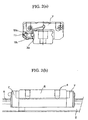
- FIG. 4 shows the second embodiment of the present invention.
- a chain-guide member 214 for supporting the ball chain 20 has no projection unlike the first embodiment.
- the structure in which the chain-guide member 214 has no projection in the edges of the loaded-ball running groove 10 makes it possible to decrease the distance between the movable block 4 and the guide rail 2 in comparison with the first embodiment.
- the depths of the loaded-ball running groove 10 and the loaded-ball-running counter-groove 5 can therefore be increased.
- the chain-guide member 214 makes a positional guide for the ball chain in the width direction of the grooves.
- the central point of the joint member 22 in its thickness direction is identical with the center "O" of the ball.
- the shift of the central point of the joint member 22 from the center of the ball requires the increased distance between the movable block 4 and the guide rail 2 accordingly, thus makes it impossible to increase the depths of the loaded-ball running groove 10 and the loaded-ball running counter-groove 5 accordingly.
- FIG. 5 shows the third embodiment of the present invention.
- each of the loaded-ball running groove 310 and the loaded-ball running counter-groove 305 is changed into a Gothic arc-groove shape, in which two circular arcs C1, C2 are combined with each other and a longitudinal line passing through the deepest point of each of the grooves 305, 310 locates between these arcs.
- the loaded-ball running groove 310 and the loaded-ball running counter-groove 305 are formed into such a Gothic arc-groove shape, it is preferable to determine the radius of curvature of the circular arcs C1, C2 of the loaded-ball running groove 310 and the loaded-ball running counter-groove 305 so as to be identical with a length of about 55 percent of the diameter of the ball.
- the depth of the loaded-ball running groove 310 and the loaded-ball running counter-groove 305 is preferable to be identical with a length of about 40 percent of the diameter of the ball.
- FIG. 6 shows a table guide apparatus in which the linear motion guide apparatus as shown in FIG. 5 are used.
- the table guide apparatus is also designed so that moments ML, MR in the opposite directions to each other are applied to the movable blocks 4, respectively, in the same manner as in the table guide apparatus as shown in FIG. 3, in a state in which the two sets of linear motion guide apparatus 1L, 1R are fitted between the stationary bed 31 and the table 32.
- the directions of the contact angle lines S1L1, S2L2; S1R1, S2R2 incline down toward the central side of the stationary bed 31 relative to the horizontal line H.
- FIG. 7 shows the fourth embodiment of the present invention.
- each of the loaded-ball running groove 310 and the loaded-ball running counter-groove 305 is formed into the Gothic arc-groove shape, in which the two circular arcs C1, C2 are combined with each other, in the same manner as in the third embodiment described above, and the chain-guide member for supporting the ball chain has no projection in the edges of the loaded-ball running groove 310 of the movable block 4 in the same manner as in the second embodiment described above.
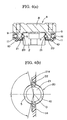
- FIGS. 8 and 9 show the fifth embodiment of the present invention.
- the loaded-ball running groove and the loaded-ball running counter-groove have the two-points contact structure in which the ball comes into contact with the pair of circular arc-grooves, or the four-points contact structure in which the ball comes into contact with the pair of Gothic arc-grooves.
- any one of the loaded-ball running groove and the loaded-ball running counter-groove, which are formed on the movable block 4 and the guide rail 2, respectively, has the circular arc-shape, and the other of them has the Gothic arc-shape.
- Such a combination of these groove shapes provides a three-point contact structure for the ball.
- Such a structure can provide an intermediate characteristic property between the two-point contact structure and the four-point contact structure so that a misalignment compensation property can become more excellent in comparison with the four-point contact structure and rigidity in the swinging direction and the vertical direction can be improved in comparison with the two-point contact structure.
- the example as shown in FIG. 8 has a combination of the Gothic arc-groove structure, which is applied on each of the loaded-ball running grooves 310 formed on the opposite sides of the movable block 4, with the circular arc-groove structure, which is applied on each of the loaded-ball running counter-grooves 5 formed on the opposite sides of the guide rail 2.
- deviation of the ball 3a from the loaded-ball running counter-groove 5 of the guide rail in the width direction of the groove becomes larger than deviation of the ball 3a from the loaded-ball running groove 310 of the movable block 4 in the width direction of the groove.
- the example as shown in FIG. 9 has a combination of the circular arc-groove structure, which is applied on each of the loaded-ball running grooves 10 formed on the opposite sides of the movable block 4, with the Gothic arc-groove structure, which is applied on each of the loaded-ball running counter-grooves 305 formed on the opposite sides of the guide rail 2.
- deviation of the ball 3a from the loaded-ball running groove 10 of the movable block 4 in the width direction of the groove becomes larger than deviation of the ball 3a from the loaded-ball running counter-groove 305 of the guide rail 2 in the width direction of the groove.
- FIG. 10(a) shows a structural example of the table guide apparatus in which the linear motion guide apparatus as shown in FIG. 8 are used
- FIG. 10(b) shows a structural example of the table guide apparatus in which the linear motion guide apparatus as shown in FIG. 9 are used.
- the table guide apparatus is also designed so that moments ML, MR in the opposite directions to each other (i.e., the outward tilting directions in FIG. 10(a) in solid lines) are applied to the movable blocks 4, respectively, in the same manner as in the table guide apparatus as shown in FIG. 3, in a state in which the two sets of linear motion guide apparatus 1L, 1R are fitted between the stationary bed 31 and the table 32.
- FIG. 10(a) there is obtained a contact structure in which, of the contact angle lines S1L1, S1L2, S1L0; S2L0, S2L1, S2L2; S1R0, S1R1, S1R2; S2R0, S2R1, S2R2 of the balls 3a locating opposite sides of each of the movable blocks 4L, 4R of the two sets of liner motion guide apparatus 1L, 1R, the contact angle lines S1L0, S2L0, S1R0, S2R0, which correspond to the circular arc-groove, incline down toward the central side of the stationary bed 31 relative to the horizontal line H.
- FIG. 10(b) there is obtained a contact structure in which, of the contact angle lines S1L0, S1L1, S1L2; S2L1, S2L2, S2L0; S1R0, S1R1, S1R2; S2R1, S2R2, S2R0 of the balls 3a locating opposite sides of each of the movable blocks 4L, 4R of the two sets of liner motion guide apparatus 1L, 1R, the contact angle lines S1L0, S2L0, S1R0, S2R0, which correspond to the circular arc-groove, incline down toward the central side of the stationary bed 31 relative to the horizontal line H.
- the ball When the above-mentioned angle exceeds the prescribed angle ⁇ 1, the ball is put into the two-point contact state having one contact point of the ball with the single circular arc C0 of the circular-arc groove and the other contact point of the ball with the first circular arc C1 of the Gothic arc groove, which is symmetric with the above-mentioned one contact point with respect to the center "O" of the ball, and the other second circular arc C2 of the Gothic arc groove does not come into contact with the ball, as shown in FIG. 10(d).
- the opposite movable blocks 4, 4 are mounted in an inclined state in such an active manner.
- the guide rails of the two sets of the linear motion guide apparatus are fixed on the stationary bed so as to parallelly spaced apart from each other and the table is mounted on these movable blocks in a usual manner, there exists an inevitable fitting error.
- the fitting error can be compensated and the movable blocks simultaneously incline, resulting in change in the contact angle.
- the small fitting error causes the contact angle of the ball to vary so as to provide the inclined state of the movable blocks. It is therefore possible to suppress play in the table guide apparatus.
- the four-point contact structure can provide almost no play, but has a low misalignment compensation property.
- the two-point contact structure has a high misalignment compensation property, but provides much play. It is therefore effective to incline the movable blocks having the two-point contact structure in an active manner as mentioned above to suppress the play.
- the three-point contact structure has a middle misalignment compensation property and can provide the play, which is less than that of the two-point contact structure and more than that of the four-point contact structure.
- the exemplified liner motion guide apparatus are described as types having the guide rail in which the opposite loaded-ball running counter-grooves have any one of the circular arc shape and the Gothic arc shape.
- the combination of the circular arc grooves is used for the set of the loaded-ball running groove and the loaded-ball running counter-groove with respect to one of the trains of balls locating in the opposite sides of the guide rail so as to provide the two-point contact structure
- the combination of the Gothic arc grooves is used for the set of the loaded-ball running groove and the loaded-ball running counter-groove with respect to the other of the above-mentioned trains of balls so as to provide the four-point contact structure.
- the combination of the two-point contact structure with the three-point contact structure and the combination of the three-point contact structure with the four-point contact structure may be used.
- the present invention it is possible to prevent the ball from coming off the loaded-ball running groove and the loaded-ball running counter-groove by holding the front and rear sides of the ball by means of the ball-supporting members locating in these grooves.
- the ball-supporting members locate within the loaded-ball running groove and the loaded-ball running counter-groove so that the ball-supporting members can be made large to the extent that their size is substantially identical with the diameter of the ball, irrespective of the depths of these grooves. It is therefore possible to support the balls surely.
- the opposing surfaces of the movable block and the guide rail are brought into the closer relationship to the joint member to increase the depths of the loaded-ball running groove and the loaded-ball running counter-groove as much as possible. It is therefore possible to prevent the ball from coming into contact with the edges of the grooves even when the deviation of the contact points of the ball with the grooves in their width direction occurs. There can accordingly be avoided the occurrence of the problem of the edge load, in which stress concentrates in the edges of the grooves. It is therefore possible to extend the range of an area within which the ball can come into contact with the grooves in their width direction, thus permitting selection of an appropriate contact angle within an extended range thereof.
- the fitting length of the ball into the loaded-ball-running groove and the loaded-ball-running counter-groove in their depth direction also increases. Even when there applies the load having a function of shifting parallelly the opposing surfaces of the movable block and the guide rail in opposite directions to each other in the width direction of the grooves, the contact points of the ball with the grooves deviate within an intermediate region between the deepest point of the grooves and the edges thereof, thus making it possible to prevent the ball from coming into contact with the edges of the grooves.
- lateral direction load which has a function of urging the support leg portions of the movable block against the opposite side surfaces of the guide rail, applies so as to compress the ball locating between the guide rail and the corresponding loaded-ball running groove of the support leg portions.
- the ball bears the lateral direction load without causing any undesirable movement of the movable block.
- the ball chain has a non-endless belt structure, it is possible to carry out an assembling operation in a very easy manner.
- Each of the loaded-ball running grooves and the loaded-ball running counter-grooves may be formed into a circular arc-groove shape having a single circular arc in a cross-section.
- a circular arc-groove shape permits the ball to move relatively freely in the grooves in their width direction. It is therefore preferable to adopt an increased depth structure of the grooves and an approximation structure of the cross-sectional shape thereof to the contour of the ball as in the present invention.
- Each of the loaded-ball running grooves and the loaded-ball running counter-grooves may be formed into the Gothic arc-groove shape having two circular arcs in a cross-section.
- Such a Gothic arc-groove shape can prevent more effectively the ball from moving in the width direction of the grooves in comparison with the circular arc-groove shape.
- the support of the balls with the use of the ball chain permits, in the same manner as the circular arc-groove shape, to increase the depths of the loaded-ball running grooves and the loaded-ball running counter-grooves as much as possible, thus preventing the occurrence of the edge load.
- a chain-guide member may be provided on the surface of the movable block, which is in a vicinity of the loaded-ball running groove thereof, the chain-guide member having projections that come into contact with the joint members to prevent the ball chain from coming off the movable block.
- the projections of the chain-guide member can prevent the ball chain from sagging down when the guide rail is pulled out of the movable block. In case where the ball chain has a non-endless belt structure, it is possible to prevent effectively the ball chain from sagging down.
- At least one of the ball return passage and an inner peripheral portion of the ball direction changing passage may be formed of a resin-formed body, which is integrally formed with the block body.
- At least one of the ball return passage, an inner peripheral portion of the ball direction changing passage and the chain-guide member may be formed of a resin-formed body, which is integrally formed with the block body.
- the chain-guide member can also be formed precisely, thus preventing it from coming into contact with the ball chain in an unfavorable manner.
- the table guide apparatus of the present invention two sets of the linear motion guide apparatus are provided, and the guide rails of the two sets of the apparatus are fixed on a stationary bed so as to be parallelly spaced apart from each other, and a table is mounted on the movable blocks of the two sets of the apparatus in a state that moments having functions of swinging the movable blocks around their longitudinal axis relative to the guide rails in opposite directions are given to the movable blocks.
- the linear motion guide apparatus itself can bear the vertical direction load, the lateral direction load and the moment load, while suppressing play. Arrangement of the movable blocks of the two sets of the linear motion guide apparatus in an inclined state makes it possible to suppress play effectively in the table guide apparatus.
Applications Claiming Priority (1)
| Application Number | Priority Date | Filing Date | Title |
|---|---|---|---|
| PCT/JP1998/005162 WO2000029756A1 (fr) | 1997-05-15 | 1998-11-17 | Dispositif de guidage de mouvement lineaire et dispositif de transfert de table |
Publications (2)
| Publication Number | Publication Date |
|---|---|
| EP1055834A1 true EP1055834A1 (de) | 2000-11-29 |
| EP1055834A4 EP1055834A4 (de) | 2002-01-23 |
Family
ID=14209401
Family Applications (1)
| Application Number | Title | Priority Date | Filing Date |
|---|---|---|---|
| EP98953074A Withdrawn EP1055834A4 (de) | 1998-11-17 | 1998-11-17 | Linearführungsvorrichtung und übertragungstafel |
Country Status (3)
| Country | Link |
|---|---|
| EP (1) | EP1055834A4 (de) |
| KR (1) | KR20010030842A (de) |
| WO (1) | WO2000029756A1 (de) |
Cited By (2)
| Publication number | Priority date | Publication date | Assignee | Title |
|---|---|---|---|---|
| WO2003021120A1 (fr) * | 2001-08-30 | 2003-03-13 | Thk Co., Ltd. | Verin lineaire |
| US7241048B2 (en) | 2002-08-14 | 2007-07-10 | Rexroth Star Gmbh | Linear guide device, chain body, and method of producing a chain body |
Families Citing this family (3)
| Publication number | Priority date | Publication date | Assignee | Title |
|---|---|---|---|---|
| JP4454192B2 (ja) * | 2001-08-07 | 2010-04-21 | Thk株式会社 | 案内装置の転動体干渉防止具 |
| CN109780055A (zh) * | 2017-11-15 | 2019-05-21 | 锕玛科技股份有限公司 | 移动导引装置用的链带保持器 |
| US20230288955A1 (en) * | 2020-07-24 | 2023-09-14 | Lg Electronics Inc. | Flexible display device |
Family Cites Families (4)
| Publication number | Priority date | Publication date | Assignee | Title |
|---|---|---|---|---|
| JPH0253517U (de) * | 1988-10-11 | 1990-04-18 | ||
| JP2938712B2 (ja) * | 1993-05-11 | 1999-08-25 | テイエチケー株式会社 | ラック及びピニオンを用いた自走テーブル装置 |
| JPH1089359A (ja) * | 1996-09-12 | 1998-04-07 | Thk Kk | 直線運動案内装置 |
| JP2898948B2 (ja) * | 1997-07-31 | 1999-06-02 | テイエチケー株式会社 | 転がり案内装置 |
-
1998
- 1998-11-17 EP EP98953074A patent/EP1055834A4/de not_active Withdrawn
- 1998-11-17 KR KR1020007003500A patent/KR20010030842A/ko not_active Application Discontinuation
- 1998-11-17 WO PCT/JP1998/005162 patent/WO2000029756A1/ja not_active Application Discontinuation
Non-Patent Citations (2)
| Title |
|---|
| No further relevant documents disclosed * |
| See also references of WO0029756A1 * |
Cited By (3)
| Publication number | Priority date | Publication date | Assignee | Title |
|---|---|---|---|---|
| WO2003021120A1 (fr) * | 2001-08-30 | 2003-03-13 | Thk Co., Ltd. | Verin lineaire |
| US7241048B2 (en) | 2002-08-14 | 2007-07-10 | Rexroth Star Gmbh | Linear guide device, chain body, and method of producing a chain body |
| DE10237278B4 (de) * | 2002-08-14 | 2008-03-13 | Bosch Rexroth Mechatronics Gmbh | Linearführungseinrichtung Kettenkörper Verfahren zur Herstellung eines Kettenkörpers |
Also Published As
| Publication number | Publication date |
|---|---|
| EP1055834A4 (de) | 2002-01-23 |
| WO2000029756A1 (fr) | 2000-05-25 |
| KR20010030842A (ko) | 2001-04-16 |
Similar Documents
| Publication | Publication Date | Title |
|---|---|---|
| KR100319446B1 (ko) | 복렬 볼체인을 갖춘 직선운동 안내장치 | |
| US5755516A (en) | Rolling guide apparatus and method of manufacturing movable block of rolling guide apparatus | |
| US5951168A (en) | Rolling guide apparatus | |
| EP1199487B1 (de) | Linearführungseinheiten mit Trennkörperverbindungsmitteln | |
| KR870000418B1 (ko) | 직선 슬라이드 베어링과 직선슬라이드 테이블유닛 | |
| TWI375758B (de) | ||
| US4952075A (en) | Linear motion ball bearing assembly | |
| US5391003A (en) | Rolling guide unit | |
| US4702622A (en) | Linear slide roller bearing unit | |
| EP1055834A1 (de) | Linearführungsvorrichtung und übertragungstafel | |
| US4489990A (en) | Recirculating-ball linear bearing assembly with a pair of opposed guide rails | |
| US4572590A (en) | Linear ball bearing unit | |
| US10266218B2 (en) | Tracked chassis and work machine having a track drive | |
| US4553794A (en) | Linear slide roller bearing unit | |
| JP3497460B2 (ja) | 無段変速機用ベルト | |
| US6049988A (en) | Linear motion guiding apparatus | |
| CN100592992C (zh) | 汽车座椅的纵向导轨装置 | |
| US6210039B1 (en) | Linear motion guide unit and table guide apparatus utilizing the same | |
| US4558910A (en) | Linear slide roller bearing unit | |
| US20230184291A1 (en) | Motion guide apparatus | |
| US6287005B1 (en) | Roller guiding apparatus | |
| JPH1089359A (ja) | 直線運動案内装置 | |
| EP0460721A1 (de) | Profiliertes Riemenglied | |
| US4505521A (en) | Linear slide roller bearing unit | |
| US5375931A (en) | Linear motion bearing |
Legal Events
| Date | Code | Title | Description |
|---|---|---|---|
| PUAI | Public reference made under article 153(3) epc to a published international application that has entered the european phase |
Free format text: ORIGINAL CODE: 0009012 |
|
| 17P | Request for examination filed |
Effective date: 20000721 |
|
| AK | Designated contracting states |
Kind code of ref document: A1 Designated state(s): DE FR GB IT |
|
| A4 | Supplementary search report drawn up and despatched |
Effective date: 20011206 |
|
| AK | Designated contracting states |
Kind code of ref document: A4 Designated state(s): DE FR GB IT |
|
| 17Q | First examination report despatched |
Effective date: 20020423 |
|
| STAA | Information on the status of an ep patent application or granted ep patent |
Free format text: STATUS: THE APPLICATION IS DEEMED TO BE WITHDRAWN |
|
| 18D | Application deemed to be withdrawn |
Effective date: 20020904 |