EP1055082B1 - Wärmerückgewinnungseinheit - Google Patents
Wärmerückgewinnungseinheit Download PDFInfo
- Publication number
- EP1055082B1 EP1055082B1 EP99904342A EP99904342A EP1055082B1 EP 1055082 B1 EP1055082 B1 EP 1055082B1 EP 99904342 A EP99904342 A EP 99904342A EP 99904342 A EP99904342 A EP 99904342A EP 1055082 B1 EP1055082 B1 EP 1055082B1
- Authority
- EP
- European Patent Office
- Prior art keywords
- heat transfer
- support plate
- heat recovery
- horizontal
- exhaust gas
- Prior art date
- Legal status (The legal status is an assumption and is not a legal conclusion. Google has not performed a legal analysis and makes no representation as to the accuracy of the status listed.)
- Expired - Lifetime
Links
Images


Classifications
-
- F—MECHANICAL ENGINEERING; LIGHTING; HEATING; WEAPONS; BLASTING
- F22—STEAM GENERATION
- F22B—METHODS OF STEAM GENERATION; STEAM BOILERS
- F22B1/00—Methods of steam generation characterised by form of heating method
- F22B1/02—Methods of steam generation characterised by form of heating method by exploitation of the heat content of hot heat carriers
- F22B1/18—Methods of steam generation characterised by form of heating method by exploitation of the heat content of hot heat carriers the heat carrier being a hot gas, e.g. waste gas such as exhaust gas of internal-combustion engines
- F22B1/1807—Methods of steam generation characterised by form of heating method by exploitation of the heat content of hot heat carriers the heat carrier being a hot gas, e.g. waste gas such as exhaust gas of internal-combustion engines using the exhaust gases of combustion engines
- F22B1/1815—Methods of steam generation characterised by form of heating method by exploitation of the heat content of hot heat carriers the heat carrier being a hot gas, e.g. waste gas such as exhaust gas of internal-combustion engines using the exhaust gases of combustion engines using the exhaust gases of gas-turbines
-
- F—MECHANICAL ENGINEERING; LIGHTING; HEATING; WEAPONS; BLASTING
- F22—STEAM GENERATION
- F22B—METHODS OF STEAM GENERATION; STEAM BOILERS
- F22B37/00—Component parts or details of steam boilers
- F22B37/02—Component parts or details of steam boilers applicable to more than one kind or type of steam boiler
- F22B37/10—Water tubes; Accessories therefor
- F22B37/20—Supporting arrangements, e.g. for securing water-tube sets
- F22B37/202—Suspension and securing arrangements for contact heating surfaces
Definitions
- This invention relates to the field of combined cycle systems having a gas turbine and an associated heat recovery steam generator. More particularly, this invention relates to a heat recovery assembly for use in a heat recovery steam generator.
- Gas turbines have been widely used to provide electrical power, usually as a standby for both peak power and reserve power requirements in the utility industry. Gas turbines are preferred because of their rapid starting capability and low capital costs. Conventional gas turbines, however, operate with reduced thermal efficiency due to the high exit temperatures of the exhaust gas stream and the resulting thermal loss. Therefore, a gas turbine is often combined with the heat recovery steam generator to improve overall system efficiency.
- the heat recovery steam generator can be employed to drive a steam turbine for power output or to provide process steam in cogeneration cycles.
- Heat recovery steam generators typically have either a vertical exhaust gas flow or a horizontal exhaust gas flow through arrangements of heat recovery and air pollution control assemblies.
- the heat recovery assemblies, or heat exchange circuits conventionally include superheaters, evaporators, economizers and preheaters.
- heat recovery steam generators having vertical exhaust gas flow the exhaust gas stream from the gas turbine flows upward through stacked arrangements of heat recovery assemblies and air pollution control assemblies.
- These heat recovery assemblies of the heat recovery steam generators having vertical exhaust gas flow employ horizontally oriented heat transfer tubes.
- the horizontally oriented heat transfer tubes have forced circulation of a heat transfer fluid therethrough. The use of horizontally oriented heat transfer tubes having forced circulation can permit rapid start up of the heat recovery steam generator.
- the heat transfer tubes extend through vertical pairs of spaced apart parallel heat transfer tube support plates.
- the horizontal tubes are arranged in horizontal rows, a conventional heat recovery assembly having many rows.
- a heat transfer assembly has more than 20 rows of heat transfer tubes.
- the heat transfer tube support plates are suspended within the housing.
- the mechanical load and thermal stresses exerted on the heat transfer tube support plate are in the same vertical direction when a heat recovery assembly with horizontal heat transfer tubes is employed in a heat recovery steam generator with vertical exhaust gas flow.
- the mechanical stress on the support plates is generally along a vertical line due to the suspended arrangement of the support plates.
- the thermal gradient and therefore the thermal stresses on the heat transfer tube support plates are generally constant along any given horizontal line, but vary in the vertical direction. The vertical variation in the thermal gradient and therefore the thermal stresses arises from the cooling of the exhaust gas during passage through the heat recovery assembly.
- the support plates are free to expand down as the heat recovery assembly heats up due to the suspension of the support plates in the housing.
- the resulting downward expansion and therefore the thermal stress is in a generally uniform manner.
- the thermal expansion of the upper portion of the support plate will be less than the thermal expansion of the lower portion of the support plate due to the variation of the thermal gradient along a vertical line. Again, however, the thermal expansion along any given horizontal line is uniform resulting in a uniform downward expansion of the support plate.
- Heat recovery steam generators having horizontal exhaust gas flow have vertically upright heat recovery and air pollution control assemblies.
- the heat transfer tubes of the heat recovery assemblies are vertically oriented and have natural circulation of the heat transfer fluid therethrough.
- Horizontal exhaust gas flow is particularly preferred for heat recovery steam generators having limitations on height or structure compared to the height or structure typically required for a vertically oriented exhaust gas flow path.
- the use of a conventional heat recovery assembly having horizontally oriented heat transfer tubes in a heat recovery steam generator having a horizontal gas flow results in distortion or warpage of the conventional heat transfer tube support plates.
- the support plate of a conventional heat recovery assembly having horizontal heat transfer tubes is relatively wide, supporting many rows of heat transfer tubes. Typically, a heat recovery assembly has more than 20 rows of heat transfer tubes.
- the mechanical load on the heat transfer tube support plates is in the vertical direction due to the suspension of the support plates within the housing.
- the thermal gradient on the support plate is generally constant along a vertical line in contrast to a vertical exhaust gas flow wherein the thermal gradient is generally constant along a horizontal line.
- the thermal gradient varies along any given horizontal line of the support plate as the horizontally flowing exhaust gas is cooled by passage through the heat recovery assembly.
- the portion of the support plate in the upstream direction will generally expand vertically downward a greater amount than the support plate portion in the horizontal downstream direction due to the upstream portion having a generally higher temperature. Therefore, the mechanical and thermal stresses within the support plate are perpendicular to each other. The result of the non-parallel arrangement of the mechanical and thermal stresses is the distortion or warpage of the support plate and the potential for failure of the heat transfer tubes.
- US Patent Number 4,619,315 to Waryasz discloses a support bracket 46 for a heat recovery steam generator wherein the support bracket 46 comprises a plurality of plates 48 supporting a plurality of heat exchange tubes 50.
- the plates 48 are interconnected to form the support bracket 46 and are thus not separate plate segments otherwise free to move relative to one another to accommodate any thermal expansion requirements.
- the exhaust gas 2 of a gas turbine 1 is introduced into the waste heat retrieving heat exchanger 4 and heat exchange is effected between feed water in an evaporator 5.
- the heat transfer tubes 20 of the evaporator 5 are arranged horizontally in multi-tube up-and-down stages and the inlet sections as well as the outlet sections of respective heat transfer tubes 2- are connected to the inlet headers 21 and the outlet headers 22 in each group of heat transfer tubes.
- the inlet headers 21 and the outlet headers 22 are provided in corresponding to respective heat transfer tubes groups so that the central axises thereof are orthogonal and horizontal to the central axises of respective heat transfer tube groups.
- the feed water generates boiling phenomena in the evaporator 5 during flowing therethrough and flows after becoming two-phase flow, however, flow amount control, effected by a circulating pump 23, may have good stability and controllability because the heat transfer tubes are horizontal tubes.
- the outlet headers 22 are provided in horizontal respectively, therefore, the feed water flows into a steam drum smoothly.
- an exhaust gas heat recovery unit which comprises a plurality of ribbed tubes supported by carrier plates having corresponding bores through which the ribbed tubes extend, whereby the ribbed tubes are in part supported by their own ribs.
- a circulating steam generator which can be coupled with an apparatus - in particular, a gas turbine - for recovering heat from the hot exhaust gas produced therefrom.
- the circulating steam generator includes a plurality of steam heat surfaces (2,3) which are comprised of tubes arranged in a serpentine manner and communicated with headers (4, 11) to thereby form water-steam circulation loops.
- the steam heat surfaces (2,3) are disposed in horizontal orientations in a substantially horizontal exhaust gas flow path (1) and are communicated at their inlet and outlet ends with vertically extending headers (4, 11).
- the combined cycle system in accordance with the invention has a gas turbine and heat recovery steam generator having horizontal exhaust gas flow with a horizontal tube heat transfer assembly with segmented heat transfer tube support plates for the support of horizontally oriented heat transfer tubes.
- the heat transfer assembly with horizontally oriented heat transfer tubes is preferably positioned as the first heat transfer assembly in the upstream direction of the exhaust gas flow, but can alternately or additionally be positioned in the downstream direction of the exhaust gas flow.
- the heat recovery assembly employs a vertically segmented heat transfer support plate assembly whereby the support plate segments are sufficiently horizontally narrow to minimize thermal gradients horizontally across the individual support plate segments and therefore reduce the potential for warpage or distortion of the support plate assembly that could affect the heat transfer tubes mounted thereto.
- the heat recovery assembly has multiple vertically arranged rows of horizontally oriented heat transfer tubes.
- the vertically arranged rows are transverse to the direction of the gas flow path and are spaced apart in the direction of the gas flow path.
- the support plate assembly is vertically segmented parallel to the vertical rows of heat transfer tubes wherein less than three and preferably only two vertical rows of the heat transfer tubes are mounted to each support plate segment.
- a width for each support plate segment of two vertical rows of heat transfer tubes reduces the thermal gradient across the support plate segment.
- the reduced thermal gradient substantially reduces the potential for warpage of the individual support plate segments.
- the reduced warpage of the individual support plate segment reduces the potential for mechanical failure of the heat recovery assembly.
- the heat transfer assembly of the invention is employed of heat recovery steam generators having horizontal exhaust gas flow.
- the use of the heat recovery assembly of the invention having horizontal heat transfer tubes and forced circulation of the heat transfer fluid therethrough allows for a heat recovery steam generator with horizontal exhaust gas flow having rapid start up capabilities compared to conventional heat recovery steam generators with horizontal exhaust gas flow.
- An object of the invention is to provide a support plate for use in the heat recovery assembly having horizontally oriented heat transfer tubes with forced circulation of a heat transfer fluid therethrough.
- Another object of the invention is to provide a heat transfer tube support plate having a reduced potential warpage when employed with horizontally oriented heat transfer tubes in the heat recovery steam generator having a generally horizontal exhaust gas flow.
- a gas turbine combined cycle system 10 in accordance with the invention has a gas turbine 12 and a heat recovery steam generator 14.
- a duct 16 directs the exhaust gas stream 18 from the gas turbine 12 to the heat recovery steam generator 14.
- the heat recovery steam generator 14 has a housing 20 having a diffuser or inlet portion 22 and a full cross-section portion 24.
- the housing 20 defines a generally horizontal gas flow path therethrough.
- the inlet portion 22 of the housing 20 expands the exhaust gas stream from the reduced area of the duct 16 to the full cross-section portion 24 of the housing 20.
- the horizontal tube heat recovery assembly 26 Positioned within the full cross-section portion 24 is a horizontal tube heat recovery assembly 26.
- the horizontal tube heat recovery assembly 26 has multiple horizontally oriented heat transfer tubes 34.
- the tubes 34 are oriented across or perpendicular to the exhaust gas stream 18.
- a pump 29 circulates a heat transfer fluid through the heat transfer tubes 34.
- the heat transfer tubes 34 are preferably connected for once through circulation of the heat transfer fluid.
- the housing 20 contains additional heat recovery assemblies 28, 30 and air pollution control assemblies 32.
- the horizontal tube heat recovery assembly 26 is preferably positioned at the first circuit or heat recovery unit in the upstream direction, but can be readily employed for heat recovery at any position within the housing 20.
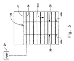
- the heat transfer tubes 34 are arranged in parallel vertical rows 36.
- the rows 36 extend in the downstream direction of the exhaust gas stream 18.
- the rows 36 of heat transfer tubes 34 are mounted to a pair of transversely spaced apart support plate assemblies 38.
- the support plate assemblies 38 are perpendicular to the heat transfer tubes 34 and parallel to the exhaust gas stream 18.
- Each support plate assembly 38 is formed of multiple vertically oriented support plate segments 40a,b,c.
- Each support plate segment 40a,b,c supports less than three rows 36 of heat transfer tubes 34.
- Preferably each support plate segment 40a,b,c supports two rows 36 of heat transfer tubes 34.
- the support plate segments 40a,b,c are suspended from a support member 31 in a conventional manner well known in the art.
- the support plate segments 40a,b,c of a particular support plate assembly 38 are preferably coplanar.
- the support plate segments 40a,b,c of a particular support plate assembly 38 are further preferably spaced apart in the direction of flow of the exhaust gas stream 18. Plate gaps 41 are therefore defined between the support plate segments 40a,b,c to prevent interference between the support plate segments 40a,b,c due to thermal expansion of the support plate segments 40a,b,c from heating by the exhaust gas stream 18.
- the hot exhaust gas stream 18 passes generally horizontally through the rows 36 of heat transfer tubes 34 supported by the support plate assembly 38.
- the support plate segments 40a in the upstream direction of support plate assemblies 38 typically receive the greatest amount of heating from the exhaust gas stream 18.
- each pair of support plate segments 40b,c positioned downstream of a particular support plate assembly 38 receives a lesser degree of heating relative to the upstream support plate segments 40a. Therefore, the support plate segments 40a in the upstream direction of the exhaust gas stream 18 experiences the greatest thermal expansion and therefore expand vertically downward the greatest relative amount.
- Support plate segments 40b,c positioned further downstream experience a relatively smaller amount of heating and therefore expand vertically downward a smaller relative amount.
- the multiple support plate segments 40a,b,c, forming the support plate assemblies 38 permit the combination of horizontal gas flow in horizontal heat transfer tubes 34 of the horizontal tube heat recovery assembly 26 without excessive thermal stress on the support plate assemblies 38.
- Each support plate segment 40a,b,c is sufficiently narrow horizontally to reduce the potential for warpage due to thermal gradients in the horizontal direction across the support plate segments 40a,b,c in the direction of the exhaust gas stream.
Landscapes
- Engineering & Computer Science (AREA)
- Chemical & Material Sciences (AREA)
- Combustion & Propulsion (AREA)
- Physics & Mathematics (AREA)
- Thermal Sciences (AREA)
- Mechanical Engineering (AREA)
- General Engineering & Computer Science (AREA)
- Life Sciences & Earth Sciences (AREA)
- Sustainable Development (AREA)
- Sustainable Energy (AREA)
- Heat-Exchange Devices With Radiators And Conduit Assemblies (AREA)
Claims (2)
- Abhitzedampferzeuger (14) mit mehreren Wärmerückgewinnungseinheiten (26, 28, 30), wobei mindestens eine der Wärmerückgewinnungseinheiten (26) mehrere Reihen (36) von horizontalen Wärmeübertragungsrohren (34) aufweist, die sich quer durch einen horizontalen Abgasstromweg (18) erstrecken, dadurch gekennzeichnet, dass:die horizontalen Wärmeübertragungsrohre (34) der Wärmerückgewinnungseinheit (26) in den mehreren Reihen (36) durch mehrere in Querrichtung voneinander beabstandete Wärmeübertragungsrohrstützplatteneinheiten (38) gestützt werden, wobei jede der Wärmeübertragungsrohrstützplatteneinheiten (38) in mehrere getrennte Stützplattensegmente (40a, 40b, 40c) unterteilt ist, die voneinander getrennt sind, und jedes der getrennten Stützplattensegmente (40a, 40b, 40c) unabhängig aufgehängt ist, sich in Richtung des horizontalen Abgasstromwegs (18) quer zu den horizontalen Wärmeübertragungsrohren (34) erstreckt und einen Teil der mehreren Reihen (36) von horizontalen Wärmeübertragungsrohren (34) stützt, und wobei die Stützplattensegmente (40a, 40b, 40c) jeder Wärmeübertragungsrohrstützplatteneinheit (38) in einer sich in Richtung des horizontalen . Abgasstromwegs (18) erstreckenden Ebene koplanar verlaufen und vertikale Plattenspalte (41) dazwischen zur Wärmeausdehnung definieren.
- Abhitzedampferzeuger (14) nach Anspruch 1, dadurch gekennzeichnet, dass jedes der Stützplattensegmente (40a, 40b, 40c) jeder Wärmeübertragungsrohrstützplatteneinheit (38) einen Teil von weniger als drei Reihen (36) der horizontalen Wärmeübertragungsrohre (34) stützt.
Applications Claiming Priority (3)
| Application Number | Priority Date | Filing Date | Title |
|---|---|---|---|
| US09/022,702 US6186221B1 (en) | 1998-02-12 | 1998-02-12 | Heat recovery assembly |
| US22702 | 1998-02-12 | ||
| PCT/US1999/001754 WO1999041546A1 (en) | 1998-02-12 | 1999-01-28 | Heat recovery assembly |
Publications (2)
| Publication Number | Publication Date |
|---|---|
| EP1055082A1 EP1055082A1 (de) | 2000-11-29 |
| EP1055082B1 true EP1055082B1 (de) | 2003-03-26 |
Family
ID=21810992
Family Applications (1)
| Application Number | Title | Priority Date | Filing Date |
|---|---|---|---|
| EP99904342A Expired - Lifetime EP1055082B1 (de) | 1998-02-12 | 1999-01-28 | Wärmerückgewinnungseinheit |
Country Status (5)
| Country | Link |
|---|---|
| US (1) | US6186221B1 (de) |
| EP (1) | EP1055082B1 (de) |
| AU (1) | AU2475699A (de) |
| DE (1) | DE69906259D1 (de) |
| WO (1) | WO1999041546A1 (de) |
Families Citing this family (2)
| Publication number | Priority date | Publication date | Assignee | Title |
|---|---|---|---|---|
| EP2026000A1 (de) * | 2007-08-10 | 2009-02-18 | Siemens Aktiengesellschaft | Dampferzeuger |
| US7621237B2 (en) * | 2007-08-21 | 2009-11-24 | Hrst, Inc. | Economizer for a steam generator |
Family Cites Families (17)
| Publication number | Priority date | Publication date | Assignee | Title |
|---|---|---|---|---|
| FR331436A (fr) * | 1902-06-23 | 1903-09-12 | Robert Wadham | Système tubulaire pour la transmission de la chaleur d'un gaz à un liquide ou à un gaz |
| US1852363A (en) * | 1928-06-16 | 1932-04-05 | Whitlock Coil Pipe Company | Heat exchanger |
| US1855552A (en) * | 1931-04-20 | 1932-04-26 | Alco Products Inc | Heat exchanger |
| US2088931A (en) * | 1936-06-17 | 1937-08-03 | Superheater Co Ltd | Supporting means for economizers |
| US2554130A (en) * | 1944-12-05 | 1951-05-22 | Phillips Petroleum Co | Heater for gases or vapors |
| US2847192A (en) * | 1955-09-12 | 1958-08-12 | Acme Ind Inc | Tube supporting and spacing structure for heat exchangers |
| US2876975A (en) * | 1957-10-28 | 1959-03-10 | Aluminum Co Of America | Tube supporting means for fluidized heat exchange apparatus |
| US4036289A (en) * | 1975-01-20 | 1977-07-19 | General Atomic Company | Heat exchanger tube bundle support system |
| US4184862A (en) * | 1976-09-30 | 1980-01-22 | Mcdonnell Douglas Corporation | Heat exchanger gas separator |
| US4246872A (en) * | 1979-04-30 | 1981-01-27 | General Electric Company | Heat exchanger tube support |
| US4262705A (en) | 1979-05-14 | 1981-04-21 | General Electric Company | Internal support structure for heat exchanger |
| CH646245A5 (de) * | 1980-09-17 | 1984-11-15 | Sulzer Ag | Waermeuebertrager mit rohrwendeln und mindestens einer gruppe von stuetzplatten fuer die rohrwendeln. |
| SU985595A1 (ru) * | 1981-07-03 | 1982-12-30 | Предприятие П/Я Р-6193 | Секци воздухоподогревател |
| JPS60251388A (ja) | 1984-05-25 | 1985-12-12 | Toshiba Corp | 排熱回収熱交換器 |
| US4619315A (en) * | 1985-04-10 | 1986-10-28 | Combustion Engineering, Inc. | Fluidized bed boiler in-bed tube support bracket |
| US4685511A (en) * | 1985-10-08 | 1987-08-11 | Westinghouse Electric Corp. | Tube support for moisture separator reheater |
| DE19700350A1 (de) * | 1997-01-08 | 1998-07-16 | Steinmueller Gmbh L & C | Durchlaufdampferzeuger mit einem Gaszug zum Anschließen an eine Heißgas abgebende Vorrichtung |
-
1998
- 1998-02-12 US US09/022,702 patent/US6186221B1/en not_active Expired - Fee Related
-
1999
- 1999-01-28 DE DE69906259T patent/DE69906259D1/de not_active Expired - Lifetime
- 1999-01-28 AU AU24756/99A patent/AU2475699A/en not_active Abandoned
- 1999-01-28 WO PCT/US1999/001754 patent/WO1999041546A1/en not_active Ceased
- 1999-01-28 EP EP99904342A patent/EP1055082B1/de not_active Expired - Lifetime
Also Published As
| Publication number | Publication date |
|---|---|
| EP1055082A1 (de) | 2000-11-29 |
| WO1999041546A1 (en) | 1999-08-19 |
| AU2475699A (en) | 1999-08-30 |
| DE69906259D1 (de) | 2003-04-30 |
| US6186221B1 (en) | 2001-02-13 |
Similar Documents
| Publication | Publication Date | Title |
|---|---|---|
| US10274192B2 (en) | Tube arrangement in a once-through horizontal evaporator | |
| CN104204664B (zh) | 用于连接单程水平蒸发器的区段的方法及设备 | |
| KR100367918B1 (ko) | 열회수식 증기 발생기 | |
| JP4549868B2 (ja) | 廃熱ボイラ | |
| CN1161556C (zh) | 热量回收蒸气发生器 | |
| JP4443216B2 (ja) | ボイラ | |
| US20170010053A1 (en) | Tube arrangement in a once-through horizontal evaporator | |
| EP1055082B1 (de) | Wärmerückgewinnungseinheit | |
| CN100420900C (zh) | 直流式蒸汽发生器及其运行方法 | |
| EP0139000B1 (de) | Dampferzeuger | |
| EP4160091B1 (de) | Dampfgenerator zur wärmerückgewinnung mit einem wärmetauscherrohrbündel | |
| JP2835226B2 (ja) | 伝熱管支持装置 | |
| JP3916784B2 (ja) | ボイラ構造 | |
| JPH0445301A (ja) | 自然循環形排熱回収熱交換器 | |
| JPS60251388A (ja) | 排熱回収熱交換器 | |
| JP3575015B2 (ja) | 排熱回収ボイラの伝熱パネル支持構造 | |
| KR200167978Y1 (ko) | 복합형 폐열회수 증기발생기 | |
| SU1721430A2 (ru) | Теплоутилизационна установка | |
| JPH0335921Y2 (de) | ||
| KR20000008414U (ko) | 복합발전용 배열회수보일러의 유동균일화 모듈 | |
| JPH11287402A (ja) | 排熱回収ボイラ | |
| JPH05296405A (ja) | 伝熱管支持装置 | |
| JPH0565761B2 (de) | ||
| JPH07217811A (ja) | ボイラ装置 |
Legal Events
| Date | Code | Title | Description |
|---|---|---|---|
| PUAI | Public reference made under article 153(3) epc to a published international application that has entered the european phase |
Free format text: ORIGINAL CODE: 0009012 |
|
| 17P | Request for examination filed |
Effective date: 20000727 |
|
| AK | Designated contracting states |
Kind code of ref document: A1 Designated state(s): DE ES FR GB IT PT |
|
| RAP1 | Party data changed (applicant data changed or rights of an application transferred) |
Owner name: ALSTOM POWER INC. |
|
| 17Q | First examination report despatched |
Effective date: 20010606 |
|
| GRAG | Despatch of communication of intention to grant |
Free format text: ORIGINAL CODE: EPIDOS AGRA |
|
| GRAG | Despatch of communication of intention to grant |
Free format text: ORIGINAL CODE: EPIDOS AGRA |
|
| GRAH | Despatch of communication of intention to grant a patent |
Free format text: ORIGINAL CODE: EPIDOS IGRA |
|
| GRAH | Despatch of communication of intention to grant a patent |
Free format text: ORIGINAL CODE: EPIDOS IGRA |
|
| GRAA | (expected) grant |
Free format text: ORIGINAL CODE: 0009210 |
|
| AK | Designated contracting states |
Designated state(s): DE ES FR GB IT PT |
|
| PG25 | Lapsed in a contracting state [announced via postgrant information from national office to epo] |
Ref country code: IT Free format text: LAPSE BECAUSE OF FAILURE TO SUBMIT A TRANSLATION OF THE DESCRIPTION OR TO PAY THE FEE WITHIN THE PRESCRIBED TIME-LIMIT;WARNING: LAPSES OF ITALIAN PATENTS WITH EFFECTIVE DATE BEFORE 2007 MAY HAVE OCCURRED AT ANY TIME BEFORE 2007. THE CORRECT EFFECTIVE DATE MAY BE DIFFERENT FROM THE ONE RECORDED. Effective date: 20030326 Ref country code: FR Free format text: LAPSE BECAUSE OF FAILURE TO SUBMIT A TRANSLATION OF THE DESCRIPTION OR TO PAY THE FEE WITHIN THE PRESCRIBED TIME-LIMIT Effective date: 20030326 |
|
| REG | Reference to a national code |
Ref country code: GB Ref legal event code: FG4D |
|
| REF | Corresponds to: |
Ref document number: 69906259 Country of ref document: DE Date of ref document: 20030430 Kind code of ref document: P |
|
| PG25 | Lapsed in a contracting state [announced via postgrant information from national office to epo] |
Ref country code: PT Free format text: LAPSE BECAUSE OF FAILURE TO SUBMIT A TRANSLATION OF THE DESCRIPTION OR TO PAY THE FEE WITHIN THE PRESCRIBED TIME-LIMIT Effective date: 20030626 |
|
| PG25 | Lapsed in a contracting state [announced via postgrant information from national office to epo] |
Ref country code: DE Free format text: LAPSE BECAUSE OF FAILURE TO SUBMIT A TRANSLATION OF THE DESCRIPTION OR TO PAY THE FEE WITHIN THE PRESCRIBED TIME-LIMIT Effective date: 20030627 |
|
| PG25 | Lapsed in a contracting state [announced via postgrant information from national office to epo] |
Ref country code: ES Free format text: LAPSE BECAUSE OF FAILURE TO SUBMIT A TRANSLATION OF THE DESCRIPTION OR TO PAY THE FEE WITHIN THE PRESCRIBED TIME-LIMIT Effective date: 20030930 |
|
| PG25 | Lapsed in a contracting state [announced via postgrant information from national office to epo] |
Ref country code: GB Free format text: LAPSE BECAUSE OF NON-PAYMENT OF DUE FEES Effective date: 20040128 |
|
| PLBE | No opposition filed within time limit |
Free format text: ORIGINAL CODE: 0009261 |
|
| STAA | Information on the status of an ep patent application or granted ep patent |
Free format text: STATUS: NO OPPOSITION FILED WITHIN TIME LIMIT |
|
| EN | Fr: translation not filed | ||
| 26N | No opposition filed |
Effective date: 20031230 |
|
| GBPC | Gb: european patent ceased through non-payment of renewal fee |
Effective date: 20040128 |