EP4160091B1 - Dampfgenerator zur wärmerückgewinnung mit einem wärmetauscherrohrbündel - Google Patents
Dampfgenerator zur wärmerückgewinnung mit einem wärmetauscherrohrbündel Download PDFInfo
- Publication number
- EP4160091B1 EP4160091B1 EP21200164.8A EP21200164A EP4160091B1 EP 4160091 B1 EP4160091 B1 EP 4160091B1 EP 21200164 A EP21200164 A EP 21200164A EP 4160091 B1 EP4160091 B1 EP 4160091B1
- Authority
- EP
- European Patent Office
- Prior art keywords
- heat exchanger
- row
- tube bundle
- tubes
- steam generator
- Prior art date
- Legal status (The legal status is an assumption and is not a legal conclusion. Google has not performed a legal analysis and makes no representation as to the accuracy of the status listed.)
- Active
Links
Images

Classifications
-
- F—MECHANICAL ENGINEERING; LIGHTING; HEATING; WEAPONS; BLASTING
- F22—STEAM GENERATION
- F22B—METHODS OF STEAM GENERATION; STEAM BOILERS
- F22B21/00—Water-tube boilers of vertical or steeply-inclined type, i.e. the water-tube sets being arranged vertically or substantially vertically
- F22B21/02—Water-tube boilers of vertical or steeply-inclined type, i.e. the water-tube sets being arranged vertically or substantially vertically built-up from substantially-straight water tubes
- F22B21/12—Water-tube boilers of vertical or steeply-inclined type, i.e. the water-tube sets being arranged vertically or substantially vertically built-up from substantially-straight water tubes involving two or more upper drums and two or more lower drums, e.g. with crosswise-arranged water-tube sets in abutting connection with drums
-
- F—MECHANICAL ENGINEERING; LIGHTING; HEATING; WEAPONS; BLASTING
- F28—HEAT EXCHANGE IN GENERAL
- F28F—DETAILS OF HEAT-EXCHANGE AND HEAT-TRANSFER APPARATUS, OF GENERAL APPLICATION
- F28F9/00—Casings; Header boxes; Auxiliary supports for elements; Auxiliary members within casings
- F28F9/02—Header boxes; End plates
- F28F9/0243—Header boxes having a circular cross-section
-
- F—MECHANICAL ENGINEERING; LIGHTING; HEATING; WEAPONS; BLASTING
- F22—STEAM GENERATION
- F22B—METHODS OF STEAM GENERATION; STEAM BOILERS
- F22B1/00—Methods of steam generation characterised by form of heating method
- F22B1/02—Methods of steam generation characterised by form of heating method by exploitation of the heat content of hot heat carriers
- F22B1/18—Methods of steam generation characterised by form of heating method by exploitation of the heat content of hot heat carriers the heat carrier being a hot gas, e.g. waste gas such as exhaust gas of internal-combustion engines
- F22B1/1807—Methods of steam generation characterised by form of heating method by exploitation of the heat content of hot heat carriers the heat carrier being a hot gas, e.g. waste gas such as exhaust gas of internal-combustion engines using the exhaust gases of combustion engines
- F22B1/1815—Methods of steam generation characterised by form of heating method by exploitation of the heat content of hot heat carriers the heat carrier being a hot gas, e.g. waste gas such as exhaust gas of internal-combustion engines using the exhaust gases of combustion engines using the exhaust gases of gas-turbines
-
- F—MECHANICAL ENGINEERING; LIGHTING; HEATING; WEAPONS; BLASTING
- F22—STEAM GENERATION
- F22B—METHODS OF STEAM GENERATION; STEAM BOILERS
- F22B1/00—Methods of steam generation characterised by form of heating method
- F22B1/02—Methods of steam generation characterised by form of heating method by exploitation of the heat content of hot heat carriers
- F22B1/18—Methods of steam generation characterised by form of heating method by exploitation of the heat content of hot heat carriers the heat carrier being a hot gas, e.g. waste gas such as exhaust gas of internal-combustion engines
- F22B1/1869—Hot gas water tube boilers not provided for in F22B1/1807 - F22B1/1861
-
- F—MECHANICAL ENGINEERING; LIGHTING; HEATING; WEAPONS; BLASTING
- F22—STEAM GENERATION
- F22B—METHODS OF STEAM GENERATION; STEAM BOILERS
- F22B21/00—Water-tube boilers of vertical or steeply-inclined type, i.e. the water-tube sets being arranged vertically or substantially vertically
- F22B21/02—Water-tube boilers of vertical or steeply-inclined type, i.e. the water-tube sets being arranged vertically or substantially vertically built-up from substantially-straight water tubes
- F22B21/12—Water-tube boilers of vertical or steeply-inclined type, i.e. the water-tube sets being arranged vertically or substantially vertically built-up from substantially-straight water tubes involving two or more upper drums and two or more lower drums, e.g. with crosswise-arranged water-tube sets in abutting connection with drums
- F22B21/123—Water-tube boilers of vertical or steeply-inclined type, i.e. the water-tube sets being arranged vertically or substantially vertically built-up from substantially-straight water tubes involving two or more upper drums and two or more lower drums, e.g. with crosswise-arranged water-tube sets in abutting connection with drums involving crossed water tubes
-
- F—MECHANICAL ENGINEERING; LIGHTING; HEATING; WEAPONS; BLASTING
- F22—STEAM GENERATION
- F22B—METHODS OF STEAM GENERATION; STEAM BOILERS
- F22B21/00—Water-tube boilers of vertical or steeply-inclined type, i.e. the water-tube sets being arranged vertically or substantially vertically
- F22B21/02—Water-tube boilers of vertical or steeply-inclined type, i.e. the water-tube sets being arranged vertically or substantially vertically built-up from substantially-straight water tubes
- F22B21/20—Water-tube boilers of vertical or steeply-inclined type, i.e. the water-tube sets being arranged vertically or substantially vertically built-up from substantially-straight water tubes involving sectional or subdivided headers in separate arrangement for each water-tube set
-
- F—MECHANICAL ENGINEERING; LIGHTING; HEATING; WEAPONS; BLASTING
- F28—HEAT EXCHANGE IN GENERAL
- F28F—DETAILS OF HEAT-EXCHANGE AND HEAT-TRANSFER APPARATUS, OF GENERAL APPLICATION
- F28F2250/00—Arrangements for modifying the flow of the heat exchange media, e.g. flow guiding means; Particular flow patterns
- F28F2250/10—Particular pattern of flow of the heat exchange media
- F28F2250/102—Particular pattern of flow of the heat exchange media with change of flow direction
-
- F—MECHANICAL ENGINEERING; LIGHTING; HEATING; WEAPONS; BLASTING
- F28—HEAT EXCHANGE IN GENERAL
- F28F—DETAILS OF HEAT-EXCHANGE AND HEAT-TRANSFER APPARATUS, OF GENERAL APPLICATION
- F28F2250/00—Arrangements for modifying the flow of the heat exchange media, e.g. flow guiding means; Particular flow patterns
- F28F2250/10—Particular pattern of flow of the heat exchange media
- F28F2250/106—Particular pattern of flow of the heat exchange media with cross flow
-
- Y—GENERAL TAGGING OF NEW TECHNOLOGICAL DEVELOPMENTS; GENERAL TAGGING OF CROSS-SECTIONAL TECHNOLOGIES SPANNING OVER SEVERAL SECTIONS OF THE IPC; TECHNICAL SUBJECTS COVERED BY FORMER USPC CROSS-REFERENCE ART COLLECTIONS [XRACs] AND DIGESTS
- Y02—TECHNOLOGIES OR APPLICATIONS FOR MITIGATION OR ADAPTATION AGAINST CLIMATE CHANGE
- Y02E—REDUCTION OF GREENHOUSE GAS [GHG] EMISSIONS, RELATED TO ENERGY GENERATION, TRANSMISSION OR DISTRIBUTION
- Y02E20/00—Combustion technologies with mitigation potential
- Y02E20/16—Combined cycle power plant [CCPP], or combined cycle gas turbine [CCGT]
Definitions
- the present invention relates to heat recovery steam generator of horizontal gas path design with a heat exchanger, such as an economizer tube bundle, and a combined cycle power plant.
- Heat exchanger tube bundles in heat recovery steam generators are used to warm up or heat an incoming fluid, condensate or feed water to almost saturated conditions.
- Different heat transfer concepts result in different heating surface sizes, depending on the performance and effectiveness of the particular configuration.
- cost and/or operational complexity of the steam generator system is affected not only by the configuration of the heating surface of the related heat exchanger, but also by the complexity and effort required to connect each tube row or tube bundle to the next.
- At least for horizontal path heat recovery steam generators - for which tube orientation is consequently vertical - it is important to maintain or achieve a proper optimum or minimum feed water velocity inside the tubes under the relevant operating conditions.
- the operating fluid is water, such as an economizer, this is in order to avoid e.g.
- Heat exchangers are known from JPH-11-287402 A ; US 1,743,326 A , FR 2 323 950 A1 , US 2006/075977 A1 , and JPH 03-117801 A .
- a fluid is guided through the tubes of the tube bundle.
- the fluid is particularly fed to the parallel tubes or tube rows of the bundle through the inlet header and e.g. collected in the outlet header.
- partition plates are usually welded inside the headers.
- Such partition plates aim to create a number of subsequent circuits (tube passes) in which the feed water is forced to pass several times through the same rack in up and down flow direction.
- Subsequent racks or so-called “harps” are connected to each other by means of external piping elements, or so-called “crossovers” for instance.
- a main disadvantage of this principle is its low effectiveness in heat recovery or exchanging heat with an exhaust or flue gas, such as an exhaust gas of a gas turbine. This is due to the inherently unfavorable crossflow properties of the design, rendering the principle inefficient as regards heat recovery.
- not all of the exhaust gas can - according to this principle - be exposed to the cold water and therefore be cooled to the lowest possible temperature. Consequently, heat recovery efficiency or as the case may be the amount of exchanged heat is reduced as compared to a principal achieving a lower number of tube passes per row.
- Another known concept provides single tube rows which are connected in a series to inlet and outlet headers having usually smaller dimensions.
- the latter concept provides the advantage of dispensing with crossovers and of a higher overall efficiency of heat recovery.
- a drawback of this concept relates to its constructability being much less compact than the above-mentioned one. In turn, this also leads to an increased overall cost.
- Another disadvantage lies in the impossibility to tune water or fluid velocity, for an acceptable pressure drop, towards a balance or stable state which can be facilitated by partition plates.
- the presented novel configuration combines the advantages of known methods, whereas - at the same time - its drawbacks can be reduced or prevented at all.
- An aspect of the present invention relates to a heat recovery steam generator of horizontal gas path design comprising a heat exchanger tube bundle, wherein the heat exchanger tube bundle is functionally set up for transferring (waste) heat from a flue gas, such as exhausted by a gas turbine, to a feed water when passing it through the tube bundle.
- the heat exchanger tube bundle is of a horizontal gas path design, the tube bundle comprising a sequence or series of bottom headers and corresponding top headers, wherein each (header) unit of the sequence comprises a row of tubes for exchanging heat like a flue gas, wherein each bottom header is fluidly connected to a corresponding top header via at least two similar tube rows for passing a fluid, like e.g.
- Each unit of the sequence further comprises at least one further tube row in fluid connection with (only) one of said bottom and top header, wherein the further tube row is further fluidly connected to a header of a subsequent or approximate unit, and wherein the further row's tubes are configured for passing the fluid in a second direction opposite to the first direction.
- the heat exchanger tube bundle is preferably configured for an application of a heat recovery steam generator.
- the provided configuration of flow tubes inherently allows to tackle the above-mentioned challenges, and therewith to provide for a far improved heat exchanger design. In this way, the stringent demands of today's energy transition and related challenges for efficient components is addressed.
- the heat exchanger tube bundle comprises only two similar tube rows and only one further tube row. This advantageously allows for an easy, robust and simple construction, and at the same time to tailor and/or optimize flow, particularly downflow, stability and to avoid any related feed water flow reversion and/or disturbance.
- the heat exchanger tube bundle is configured for only one fluid pass per tube, or as the case may be, per tube row.
- the similar row's tubes are configured for an upflow fluid pass, and the further row's tubes are configured for a downflow fluid pass.
- upflow and downflow dynamics are already (or can be) optimized by the presented tube setup, e.g. featuring a favorable balance of up- and downflow behavior.
- flow instabilities can advantageously be avoided, or a stable operating range extended.
- the similar row's tubes are of equal dimension and a cross section of the further row's tubes differs from that one of the similar row's tubes.
- this embodiment advantageously enables to maintain stable upflow dynamics, and to reduce flow instabilities.
- the cross section of the further row's tubes is smaller than that one of the similar row's tubes. This can be achieved e.g. by selecting a smaller tube diameter or fewer tubes per row of the downflow tubes.
- the heat exchanger tube bundle comprises more than two similar tube rows per (header) unit.
- the heat exchanger tube bundle comprises more than two further tube rows per unit.
- the heat exchanger tube bundle is free of partition plates, crossovers and/or external piping. This embodiment advantageously eases construction, particularly saves material and additional welding effort, and also allows to achieve an improved heat transfer efficiency (see above).
- a further aspect of the present invention relates to a heat exchanger comprising the tube bundle as described herein.
- a further aspect of the present invention relates to a combined cycle power plant, wherein the heat exchanger tube bundle is applied in an economizer and/or an evaporator of the power plant.
- the power plant may to this effect comprise a steam turbine and a gas turbine or be functionally coupled to said turbines.
- the invention allows for a method of heat recovery or heat transfer from an exhaust gas in the heat exchanger, such as within an intended operation of the heat exchanger or heat recovery steam generator.
- the exhaust gas may be provided by a gas turbine engine or similar entity.
- any source of (waste) heat even when provided otherwise than through a gas turbine exhaust, can be contemplated.
- the generated steam may be used as a working fluid in a steam turbine and/or as process steam for any other industrial application.
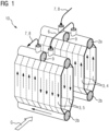
- FIG 1 shows a known principle of a heat exchanger, particularly an economizer 10 for a heat recovery steam generator (HRSG) application in a horizontal gas path design.
- the heat exchanger as shown preferably relates to a so-called “harp” design.
- the component 10 comprises a plurality of such harps or racks, wherein two racks are exemplarily depicted in Figure 1 in a series connection, which are connected to each other by means of external piping elements 6, also called “crossovers".
- crossovers external piping elements
- several rows of tubes 3 are connected to inlet and outlet collecting headers 2a, 2b, respectively.
- tubes 3 are only depicted schematically, wherein the dashed lines shall indicate an interspace and/or separation between different tubes in a row.
- Reference numeral 4 as used herein shall particularly denote a so-called upflow tube, whereas reference numeral 5 shall indicate a downflow tube, all of which characterizing the horizontal path design of heat recovery steam generators for the related heat exchanger section.
- incoming water (not explicitly indicated) is fed to the parallel tubes 3 through the respective inlet header and collected in the corresponding outlet header (cf. as well arrows in the Figures indicating flow direction of the feed water during an intended operation.
- partition plates 9 are welded inside the headers 2, which effectuate creation of a number of subsequent or separated water circuits - also called “passes per row” or “tube passes”.
- the partition plates 9 force the feed water to pass several times, e.g. twice, through the same rack in up and down flow direction.
- a number of tubes are grouped in the design of the heat exchanger as shown in Figure 1 .
- numeral 7 indicates a general feed water inlet
- numeral 8 indicates a related water outlet in the depicted tube bundle 10.
- an inlet may principally relate to an outlet, and vice versa.
- a main technical drawback of this configuration is its quite complex design and relatively low effectiveness in exchanging heat with the exhaust gas, the course of which is indicated by the larger arrow and numeral G.
- the exhaust gas G since not all exhaust gas G can be exposed to the coldest, i.e. upstream, feed water, also not the whole share of heat of gas G can be extracted by the heat exchanger 10 and transferred to the feed water.
- the gas can in this way not be cooled to the lowest possible temperature; or as the case may be, the water heated to the maximum possible temperature. Consequently, heat exchange is reduced due to this less favorable crossflow geometry, as compared to the inventive design as shown in Figures 3 onwards, for instance.
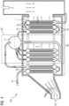
- Figure 2 shows an alternative (known) heat exchanger concept that may pertain to a so-called "harmonica"-type of economizer used for horizontal path HRSG applications.
- single, parallel tube or tube rows 3 are arranged in a series and each of which (or each row) connected to a top header 2a and an bottom header 2b.
- Each bottom header 2b is preferably fluidly connected via an upflow tube 4 with the corresponding top header 2a.
- Such a sequential unit 1 of the whole component 10 is encircled by a dashed square. In total, six sequential units or tube elements are shown connected in series.
- the larger square (not explicitly indicated) between the headers 2a, 2b indicates an exhaust or flue gas channel
- the economizer is, preferably subjected to in its intended operation, such as an operation of a related steam generator.
- the arrow G indicates a possible direction of exhaust gas for the expedient heat transfer.
- FIG 3 illustrates a simplified sketch of a heat exchanger design featuring a tube bundle according to the present invention.
- Said heat exchanger 10 may as well be set up for heat recovery steam generators (cf. Figure 4 below).
- This tube bundle 10 comprises a sequence 1 of bottom headers 2b and corresponding top headers 2a, wherein each unit 1a of the sequence comprises a row of tubes, wherein each bottom header 2b is fluidly connected to a corresponding top header 2a via at least two similar tube rows 3 for passing a fluid in a first direction between the bottom header 2b and the top header 2a, respectively.
- each unit of the sequence further comprises at least one further tube row 3 in fluid connection with one of said bottom and top header, wherein the further tube row is further fluidly connected to a header of a subsequent unit 1b.
- the further row's tubes 3 are configured for passing the fluid preferably in a second direction opposite to the first direction (cf. again arrows indicating the flow directions of a fluid guided through the tube rows in an operation of the heat exchanger 10).
- this configuration of heat exchanger tube bundle comprises a number of only four connected serial header units.
- upflow tubes 4 are arranged in fluid communication for a fluid or feed water flow from a given bottom header 2b to the top header 2a, respectively.
- the tube bundle 10 comprises only two upflow tubes 3, 4 and only one downflow tube 3, 5 per unit. It is further shown that the tube bundle 10 is configured such that it allows for only one fluid or water pass per tube or tube row.
- the fluid flow direction could as well be established vice versa, i.e. such that there are two (similar) downflow rows 3, 5 per unit and e.g. only one (further) row set up for an upwardly guided fluid.
- similar row's tubes 3, 4 and the further row's tubes 3, 4 are all of similar dimension, particularly of similar or equal cross section.
- the inventive heat exchanger is free of any partition plates, crossovers and/or external piping, thereby maintaining a compact layout.
- the design of the inventive tube bundle may be configured such that it comprises more than two similar up- or downflow tubes 3 or related tube rows connecting a given bottom header 2b and the corresponding top header 2a.
- inventive advantages may also manifest in a design with a plurality of further up- or downflow tubes (or related rows) per header unit. This would, however, most probably imply as well a plurality, particularly a larger number, of the respectively other type of tube rows.
- the inventive design stands further out for an optimized number of top headers 2a and bottom headers 2b.
- the depicted heat exchange tube bundle 10 comprises a number of four bottom headers 2b and/or a number of four, top headers 2a.
- the technical advantages are preferably intrinsic to the described configuration, e.g. number and size, of headers, upflow and downflow tube rows with which fluid flow properties may be tailored better than with any known heat exchanger design to the respective application.
- the inventive heat exchanger may relate to a so-called "Accordion" economizer design, advantageously combining the design compactness and constructability of the harp design and the effectiveness of a harmonica design. Moreover, it allows to effectively avoid downflow instability by allowing a specific design of the downflow row's tube size, i.e. independently from the other tube rows. This results in a more compact, robust and easily constructed bundle with a far greater potential of heat recovery in the operation of related steam generators or a higher-ranking power plant (cf. Figure 4 below). Particularly, as compared to the design shown in Figure 1 , the inventive concept excels in a better heating surface effectiveness and - at the same time - in a simpler construction due to a lack of crossover connections. Both advantages, in turn, result also in a cost advantage.
- FIG. 4 shows a simplified sketch of at least parts of a combined cycle power plant 100 illustrating the basic principle of its assembly, e.g. comprising a heat exchanger 10, such as the inventive heat exchanger configured for an application of heat recovery steam generator 40. Also an evaporator assembly 20 as well as a superheater 30 are shown. All of these components are preferably functionally coupled in an expedient way.
- the plant 100 may comprise or be connected to the flue gas path of a gas turbine GT via which an exhaust gas G is exposed to the superheater 40 (or vice versa). Then the superheater 30 is connected or coupled to a hot steam path - fed in by a steam drum 21 of the evaporator section 20.
- the steam ST is then expediently provided to a steam turbine of the plant 100, or to another facilty.
- the exhaust gas G Downstream of the superheater assembly 30 - also comprising dedicated tube bundles for steam generation and/or heat transfer - the exhaust gas G enters the tube bundle of the evaporator 20. Later, in a rather low temperature section, the gas G finally arrives at the economizer tube bundle 10 for efficient heat transfer operation of the plant 100.
- the assembly could also be different, such as using the heat exchanger 10 in another setup, like in a configuration for a heat transfer from any kind of waste heat and the generation of related process steam (without any superheater or turbines involved).
- the improved heat exchanger design imparts the outlined technical advantages as well to other application, such as downscaled and/or domestic application of heat exchangers.
Landscapes
- Engineering & Computer Science (AREA)
- Physics & Mathematics (AREA)
- Thermal Sciences (AREA)
- Mechanical Engineering (AREA)
- General Engineering & Computer Science (AREA)
- Chemical & Material Sciences (AREA)
- Combustion & Propulsion (AREA)
- Life Sciences & Earth Sciences (AREA)
- Sustainable Development (AREA)
- Sustainable Energy (AREA)
- Heat-Exchange Devices With Radiators And Conduit Assemblies (AREA)
Claims (9)
- Wärmerückgewinnungsdampferzeuger (40) mit horizontaler Gaswegkonstruktion, umfassend ein Wärmetauscherrohrbündel (10) mit horizontaler Gaswegkonstruktion, wobei das Wärmetauscherrohrbündel funktionell eingerichtet ist, um Wärme von einem Rauchgas (G) an ein Speisewasser oder Kondensat zu übertragen, wenn es durch das Rohrbündel geleitet wird, wobei das Rohrbündel (10) eine Abfolge (1) von unteren Sammelrohren (2b) und entsprechenden oberen Sammelrohren (2a) umfasst, wobei jede Einheit (1, 1a) der Abfolge eine Reihe von Rohren umfasst, wobei jedes untere Sammelrohr (2b) über mindestens zwei ähnliche Rohrreihen (3, 4, 5) mit einem entsprechenden oberen Sammelrohr (2a) fluidisch verbunden ist, um ein Fluid in einer ersten Richtung zwischen dem unteren Sammelrohr (2b) beziehungsweise dem oberen Sammelrohr (2a) zu leiten, und wobei jede Einheit der Abfolge ferner mindestens eine weitere Rohrreihe (3, 4, 5) umfasst, die in Fluidverbindung mit einem des unteren und des oberen Sammelrohrs steht, wobei die weitere Rohrreihe ferner mit einem Sammelrohr einer nachfolgenden Einheit (1, 1b) fluidisch verbunden ist, und wobei die Rohre (3, 4, 5) der weiteren Reihe zum Leiten des Fluids in einer zweiten Richtung, die der ersten Richtung entgegengesetzt ist, konfiguriert sind, dadurch gekennzeichnet, dass der Querschnitt der Rohre (3, 4, 5) der weiteren Reihe kleiner als der der Rohre (3, 4, 5) der ähnlichen Reihe ist.
- Rückgewinnungsdampferzeuger (40) nach Anspruch 1, wobei das Wärmetauscherrohrbündel (10) nur zwei ähnliche Rohrreihen (3, 4, 5) und nur eine weiteren Rohrreihe (3, 4, 5) umfasst.
- Rückgewinnungsdampferzeuger (40) nach Anspruch 1 oder 2, wobei das Wärmetauscherrohrbündel (10) für nur einen Fluiddurchgang pro Rohrreihe konfiguriert ist.
- Rückgewinnungsdampferzeuger (40) nach einem der vorstehenden Ansprüche, wobei die Rohre (3, 4, 5) der ähnlichen Reihe für einen Aufwärtsströmungsfluiddurchgang konfiguriert sind und die Rohre (3, 4, 5) der weiteren Reihe für einen Abwärtsströmungsfluiddurchgang konfiguriert sind.
- Rückgewinnungsdampferzeuger (40) nach einem der vorstehenden Ansprüche, wobei die Rohre (3, 4, 5) der ähnlichen Reihe eine gleiche Abmessung besitzen.
- Rückgewinnungsdampferzeuger (40) nach einem der Ansprüche 1 und 3 bis 5, wobei das Wärmetauscherrohrbündel (10) mehr als zwei ähnliche Rohrreihen (3, 4, 5) pro Einheit umfasst.
- Rückgewinnungsdampferzeuger (40) nach einem der Ansprüche 1 und 3 bis 6, wobei das Wärmetauscherrohrbündel (10) mehr als zwei weitere Rohrreihen (3, 4, 5) pro Einheit umfasst.
- Rückgewinnungsdampferzeuger (40) nach einem der vorstehenden Ansprüche, wobei das Wärmetauscherrohrbündel (10) frei von Trennplatten (9), Rohrformstücken (6) und/oder externen Rohrleitungen ist.
- Gas- und Dampfturbinenkraftwerk (100), umfassend den Wärmerückgewinnungsdampferzeuger (40) nach einem der vorstehenden Ansprüche, wobei das Wärmetauscherrohrbündel (10) in einem Economiser und/oder einem Verdampfer des Kraftwerks (100) eingesetzt wird.
Priority Applications (3)
| Application Number | Priority Date | Filing Date | Title |
|---|---|---|---|
| EP21200164.8A EP4160091B1 (de) | 2021-09-30 | 2021-09-30 | Dampfgenerator zur wärmerückgewinnung mit einem wärmetauscherrohrbündel |
| US18/689,513 US20240384945A1 (en) | 2021-09-30 | 2022-08-02 | Heat exchanger tube bundle and related heat recovery steam generator |
| PCT/EP2022/071726 WO2023051977A1 (en) | 2021-09-30 | 2022-08-02 | Heat exchanger tube bundle and related heat recovery steam generator |
Applications Claiming Priority (1)
| Application Number | Priority Date | Filing Date | Title |
|---|---|---|---|
| EP21200164.8A EP4160091B1 (de) | 2021-09-30 | 2021-09-30 | Dampfgenerator zur wärmerückgewinnung mit einem wärmetauscherrohrbündel |
Publications (2)
| Publication Number | Publication Date |
|---|---|
| EP4160091A1 EP4160091A1 (de) | 2023-04-05 |
| EP4160091B1 true EP4160091B1 (de) | 2024-09-04 |
Family
ID=78414155
Family Applications (1)
| Application Number | Title | Priority Date | Filing Date |
|---|---|---|---|
| EP21200164.8A Active EP4160091B1 (de) | 2021-09-30 | 2021-09-30 | Dampfgenerator zur wärmerückgewinnung mit einem wärmetauscherrohrbündel |
Country Status (3)
| Country | Link |
|---|---|
| US (1) | US20240384945A1 (de) |
| EP (1) | EP4160091B1 (de) |
| WO (1) | WO2023051977A1 (de) |
Family Cites Families (5)
| Publication number | Priority date | Publication date | Assignee | Title |
|---|---|---|---|---|
| US1743326A (en) * | 1926-06-17 | 1930-01-14 | Babcock & Wilcox Co | Steam generator |
| FR2323950A1 (fr) * | 1975-09-11 | 1977-04-08 | Carosso Victor Joseph | Chaudiere multitubulaire pour la production de vapeur saturee ou surchauffee |
| JP2925594B2 (ja) * | 1989-09-29 | 1999-07-28 | バブコツク日立株式会社 | 排熱回収ボイラ |
| JP3227137B2 (ja) * | 1999-02-26 | 2001-11-12 | バブコック日立株式会社 | 排熱回収ボイラ |
| EP1443268A1 (de) * | 2003-01-31 | 2004-08-04 | Siemens Aktiengesellschaft | Dampferzeuger |
-
2021
- 2021-09-30 EP EP21200164.8A patent/EP4160091B1/de active Active
-
2022
- 2022-08-02 WO PCT/EP2022/071726 patent/WO2023051977A1/en not_active Ceased
- 2022-08-02 US US18/689,513 patent/US20240384945A1/en active Pending
Also Published As
| Publication number | Publication date |
|---|---|
| US20240384945A1 (en) | 2024-11-21 |
| WO2023051977A1 (en) | 2023-04-06 |
| EP4160091A1 (de) | 2023-04-05 |
Similar Documents
| Publication | Publication Date | Title |
|---|---|---|
| EP2834561B1 (de) | Rohranordnung in einem horizontalen einmaldurchgangsverdampfer | |
| EP2839213B1 (de) | Rohr- und blendenanordnung in einem horizontalen einmaldurchgangsverdampfer | |
| US6957630B1 (en) | Flexible assembly of once-through evaporation for horizontal heat recovery steam generator | |
| US6092490A (en) | Heat recovery steam generator | |
| CA2514871C (en) | Steam generator | |
| EP3204691B1 (de) | Vertikale, berohrte überkritische durchlaufverdampferrohrschlange für einen abhitzekessel | |
| RU2546388C2 (ru) | Непрерывный парогенератор с уравнительной камерой | |
| US9267678B2 (en) | Continuous steam generator | |
| US20180142956A1 (en) | Single pass cross-flow heat exchanger | |
| WO1998027385A1 (en) | Boiler | |
| AU2018274073A1 (en) | Heat exchanger for molten salt steam generator in concentrated solar power plant | |
| US20170010053A1 (en) | Tube arrangement in a once-through horizontal evaporator | |
| EP4160091B1 (de) | Dampfgenerator zur wärmerückgewinnung mit einem wärmetauscherrohrbündel | |
| RU2351843C2 (ru) | Прямоточный парогенератор и способ эксплуатации прямоточного парогенератора | |
| US7032384B2 (en) | Steam turbine plant | |
| EP1055082B1 (de) | Wärmerückgewinnungseinheit | |
| CN111989531B (zh) | 传热管支承构造及传热管支承方法 | |
| JP4222484B2 (ja) | 排熱回収ボイラ | |
| JPS60251388A (ja) | 排熱回収熱交換器 | |
| KR200173321Y1 (ko) | 병렬배치의 열교환기 | |
| CN118729813A (zh) | 通道切换热交换器 | |
| CN105114938A (zh) | 一种蛇形管式高压给水加热器 | |
| HK40036578A (en) | Heat-transfer-tube support structure, and method for supporting heat transfer tube | |
| HK40036578B (en) | Heat-transfer-tube support structure, and method for supporting heat transfer tube | |
| JPS61289201A (ja) | 排ガスボイラ |
Legal Events
| Date | Code | Title | Description |
|---|---|---|---|
| PUAI | Public reference made under article 153(3) epc to a published international application that has entered the european phase |
Free format text: ORIGINAL CODE: 0009012 |
|
| STAA | Information on the status of an ep patent application or granted ep patent |
Free format text: STATUS: THE APPLICATION HAS BEEN PUBLISHED |
|
| AK | Designated contracting states |
Kind code of ref document: A1 Designated state(s): AL AT BE BG CH CY CZ DE DK EE ES FI FR GB GR HR HU IE IS IT LI LT LU LV MC MK MT NL NO PL PT RO RS SE SI SK SM TR |
|
| RAP1 | Party data changed (applicant data changed or rights of an application transferred) |
Owner name: NEM ENERGY B.V. |
|
| STAA | Information on the status of an ep patent application or granted ep patent |
Free format text: STATUS: REQUEST FOR EXAMINATION WAS MADE |
|
| 17P | Request for examination filed |
Effective date: 20231004 |
|
| RBV | Designated contracting states (corrected) |
Designated state(s): AL AT BE BG CH CY CZ DE DK EE ES FI FR GB GR HR HU IE IS IT LI LT LU LV MC MK MT NL NO PL PT RO RS SE SI SK SM TR |
|
| GRAP | Despatch of communication of intention to grant a patent |
Free format text: ORIGINAL CODE: EPIDOSNIGR1 |
|
| STAA | Information on the status of an ep patent application or granted ep patent |
Free format text: STATUS: GRANT OF PATENT IS INTENDED |
|
| INTG | Intention to grant announced |
Effective date: 20240415 |
|
| GRAS | Grant fee paid |
Free format text: ORIGINAL CODE: EPIDOSNIGR3 |
|
| GRAA | (expected) grant |
Free format text: ORIGINAL CODE: 0009210 |
|
| STAA | Information on the status of an ep patent application or granted ep patent |
Free format text: STATUS: THE PATENT HAS BEEN GRANTED |
|
| AK | Designated contracting states |
Kind code of ref document: B1 Designated state(s): AL AT BE BG CH CY CZ DE DK EE ES FI FR GB GR HR HU IE IS IT LI LT LU LV MC MK MT NL NO PL PT RO RS SE SI SK SM TR |
|
| REG | Reference to a national code |
Ref country code: GB Ref legal event code: FG4D |
|
| REG | Reference to a national code |
Ref country code: CH Ref legal event code: EP |
|
| REG | Reference to a national code |
Ref country code: IE Ref legal event code: FG4D |
|
| REG | Reference to a national code |
Ref country code: DE Ref legal event code: R096 Ref document number: 602021018227 Country of ref document: DE |
|
| P01 | Opt-out of the competence of the unified patent court (upc) registered |
Free format text: CASE NUMBER: APP_51904/2024 Effective date: 20240916 |
|
| REG | Reference to a national code |
Ref country code: LT Ref legal event code: MG9D |
|
| REG | Reference to a national code |
Ref country code: NL Ref legal event code: MP Effective date: 20240904 |
|
| PG25 | Lapsed in a contracting state [announced via postgrant information from national office to epo] |
Ref country code: NO Free format text: LAPSE BECAUSE OF FAILURE TO SUBMIT A TRANSLATION OF THE DESCRIPTION OR TO PAY THE FEE WITHIN THE PRESCRIBED TIME-LIMIT Effective date: 20241204 |
|
| PG25 | Lapsed in a contracting state [announced via postgrant information from national office to epo] |
Ref country code: PL Free format text: LAPSE BECAUSE OF FAILURE TO SUBMIT A TRANSLATION OF THE DESCRIPTION OR TO PAY THE FEE WITHIN THE PRESCRIBED TIME-LIMIT Effective date: 20240904 Ref country code: FI Free format text: LAPSE BECAUSE OF FAILURE TO SUBMIT A TRANSLATION OF THE DESCRIPTION OR TO PAY THE FEE WITHIN THE PRESCRIBED TIME-LIMIT Effective date: 20240904 |
|
| PG25 | Lapsed in a contracting state [announced via postgrant information from national office to epo] |
Ref country code: BG Free format text: LAPSE BECAUSE OF FAILURE TO SUBMIT A TRANSLATION OF THE DESCRIPTION OR TO PAY THE FEE WITHIN THE PRESCRIBED TIME-LIMIT Effective date: 20240904 |
|
| PG25 | Lapsed in a contracting state [announced via postgrant information from national office to epo] |
Ref country code: LV Free format text: LAPSE BECAUSE OF FAILURE TO SUBMIT A TRANSLATION OF THE DESCRIPTION OR TO PAY THE FEE WITHIN THE PRESCRIBED TIME-LIMIT Effective date: 20240904 |
|
| PG25 | Lapsed in a contracting state [announced via postgrant information from national office to epo] |
Ref country code: HR Free format text: LAPSE BECAUSE OF FAILURE TO SUBMIT A TRANSLATION OF THE DESCRIPTION OR TO PAY THE FEE WITHIN THE PRESCRIBED TIME-LIMIT Effective date: 20240904 |
|
| PG25 | Lapsed in a contracting state [announced via postgrant information from national office to epo] |
Ref country code: ES Free format text: LAPSE BECAUSE OF FAILURE TO SUBMIT A TRANSLATION OF THE DESCRIPTION OR TO PAY THE FEE WITHIN THE PRESCRIBED TIME-LIMIT Effective date: 20240904 Ref country code: RS Free format text: LAPSE BECAUSE OF FAILURE TO SUBMIT A TRANSLATION OF THE DESCRIPTION OR TO PAY THE FEE WITHIN THE PRESCRIBED TIME-LIMIT Effective date: 20241204 |
|
| REG | Reference to a national code |
Ref country code: GR Ref legal event code: EP Ref document number: 20240402752 Country of ref document: GR Effective date: 20250120 |
|
| PG25 | Lapsed in a contracting state [announced via postgrant information from national office to epo] |
Ref country code: RS Free format text: LAPSE BECAUSE OF FAILURE TO SUBMIT A TRANSLATION OF THE DESCRIPTION OR TO PAY THE FEE WITHIN THE PRESCRIBED TIME-LIMIT Effective date: 20241204 Ref country code: PL Free format text: LAPSE BECAUSE OF FAILURE TO SUBMIT A TRANSLATION OF THE DESCRIPTION OR TO PAY THE FEE WITHIN THE PRESCRIBED TIME-LIMIT Effective date: 20240904 Ref country code: NO Free format text: LAPSE BECAUSE OF FAILURE TO SUBMIT A TRANSLATION OF THE DESCRIPTION OR TO PAY THE FEE WITHIN THE PRESCRIBED TIME-LIMIT Effective date: 20241204 Ref country code: LV Free format text: LAPSE BECAUSE OF FAILURE TO SUBMIT A TRANSLATION OF THE DESCRIPTION OR TO PAY THE FEE WITHIN THE PRESCRIBED TIME-LIMIT Effective date: 20240904 Ref country code: HR Free format text: LAPSE BECAUSE OF FAILURE TO SUBMIT A TRANSLATION OF THE DESCRIPTION OR TO PAY THE FEE WITHIN THE PRESCRIBED TIME-LIMIT Effective date: 20240904 Ref country code: FI Free format text: LAPSE BECAUSE OF FAILURE TO SUBMIT A TRANSLATION OF THE DESCRIPTION OR TO PAY THE FEE WITHIN THE PRESCRIBED TIME-LIMIT Effective date: 20240904 Ref country code: ES Free format text: LAPSE BECAUSE OF FAILURE TO SUBMIT A TRANSLATION OF THE DESCRIPTION OR TO PAY THE FEE WITHIN THE PRESCRIBED TIME-LIMIT Effective date: 20240904 Ref country code: BG Free format text: LAPSE BECAUSE OF FAILURE TO SUBMIT A TRANSLATION OF THE DESCRIPTION OR TO PAY THE FEE WITHIN THE PRESCRIBED TIME-LIMIT Effective date: 20240904 |
|
| REG | Reference to a national code |
Ref country code: AT Ref legal event code: MK05 Ref document number: 1720742 Country of ref document: AT Kind code of ref document: T Effective date: 20240904 |
|
| PG25 | Lapsed in a contracting state [announced via postgrant information from national office to epo] |
Ref country code: NL Free format text: LAPSE BECAUSE OF FAILURE TO SUBMIT A TRANSLATION OF THE DESCRIPTION OR TO PAY THE FEE WITHIN THE PRESCRIBED TIME-LIMIT Effective date: 20240904 |
|
| PG25 | Lapsed in a contracting state [announced via postgrant information from national office to epo] |
Ref country code: IS Free format text: LAPSE BECAUSE OF FAILURE TO SUBMIT A TRANSLATION OF THE DESCRIPTION OR TO PAY THE FEE WITHIN THE PRESCRIBED TIME-LIMIT Effective date: 20250104 Ref country code: PT Free format text: LAPSE BECAUSE OF FAILURE TO SUBMIT A TRANSLATION OF THE DESCRIPTION OR TO PAY THE FEE WITHIN THE PRESCRIBED TIME-LIMIT Effective date: 20250106 |
|
| PG25 | Lapsed in a contracting state [announced via postgrant information from national office to epo] |
Ref country code: SM Free format text: LAPSE BECAUSE OF FAILURE TO SUBMIT A TRANSLATION OF THE DESCRIPTION OR TO PAY THE FEE WITHIN THE PRESCRIBED TIME-LIMIT Effective date: 20240904 Ref country code: RO Free format text: LAPSE BECAUSE OF FAILURE TO SUBMIT A TRANSLATION OF THE DESCRIPTION OR TO PAY THE FEE WITHIN THE PRESCRIBED TIME-LIMIT Effective date: 20240904 |
|
| PG25 | Lapsed in a contracting state [announced via postgrant information from national office to epo] |
Ref country code: EE Free format text: LAPSE BECAUSE OF FAILURE TO SUBMIT A TRANSLATION OF THE DESCRIPTION OR TO PAY THE FEE WITHIN THE PRESCRIBED TIME-LIMIT Effective date: 20240904 Ref country code: AT Free format text: LAPSE BECAUSE OF FAILURE TO SUBMIT A TRANSLATION OF THE DESCRIPTION OR TO PAY THE FEE WITHIN THE PRESCRIBED TIME-LIMIT Effective date: 20240904 |
|
| PG25 | Lapsed in a contracting state [announced via postgrant information from national office to epo] |
Ref country code: CZ Free format text: LAPSE BECAUSE OF FAILURE TO SUBMIT A TRANSLATION OF THE DESCRIPTION OR TO PAY THE FEE WITHIN THE PRESCRIBED TIME-LIMIT Effective date: 20240904 |
|
| PG25 | Lapsed in a contracting state [announced via postgrant information from national office to epo] |
Ref country code: SK Free format text: LAPSE BECAUSE OF FAILURE TO SUBMIT A TRANSLATION OF THE DESCRIPTION OR TO PAY THE FEE WITHIN THE PRESCRIBED TIME-LIMIT Effective date: 20240904 |
|
| REG | Reference to a national code |
Ref country code: CH Ref legal event code: PL |
|
| PG25 | Lapsed in a contracting state [announced via postgrant information from national office to epo] |
Ref country code: LU Free format text: LAPSE BECAUSE OF NON-PAYMENT OF DUE FEES Effective date: 20240930 |
|
| REG | Reference to a national code |
Ref country code: DE Ref legal event code: R097 Ref document number: 602021018227 Country of ref document: DE |
|
| PG25 | Lapsed in a contracting state [announced via postgrant information from national office to epo] |
Ref country code: MC Free format text: LAPSE BECAUSE OF FAILURE TO SUBMIT A TRANSLATION OF THE DESCRIPTION OR TO PAY THE FEE WITHIN THE PRESCRIBED TIME-LIMIT Effective date: 20240904 |
|
| PG25 | Lapsed in a contracting state [announced via postgrant information from national office to epo] |
Ref country code: DK Free format text: LAPSE BECAUSE OF FAILURE TO SUBMIT A TRANSLATION OF THE DESCRIPTION OR TO PAY THE FEE WITHIN THE PRESCRIBED TIME-LIMIT Effective date: 20240904 |
|
| PLBE | No opposition filed within time limit |
Free format text: ORIGINAL CODE: 0009261 |
|
| STAA | Information on the status of an ep patent application or granted ep patent |
Free format text: STATUS: NO OPPOSITION FILED WITHIN TIME LIMIT |
|
| PG25 | Lapsed in a contracting state [announced via postgrant information from national office to epo] |
Ref country code: CH Free format text: LAPSE BECAUSE OF NON-PAYMENT OF DUE FEES Effective date: 20240930 |
|
| PG25 | Lapsed in a contracting state [announced via postgrant information from national office to epo] |
Ref country code: IE Free format text: LAPSE BECAUSE OF NON-PAYMENT OF DUE FEES Effective date: 20240930 |
|
| 26N | No opposition filed |
Effective date: 20250605 |
|
| PG25 | Lapsed in a contracting state [announced via postgrant information from national office to epo] |
Ref country code: SE Free format text: LAPSE BECAUSE OF FAILURE TO SUBMIT A TRANSLATION OF THE DESCRIPTION OR TO PAY THE FEE WITHIN THE PRESCRIBED TIME-LIMIT Effective date: 20240904 |
|
| PGFP | Annual fee paid to national office [announced via postgrant information from national office to epo] |
Ref country code: DE Payment date: 20250923 Year of fee payment: 5 |
|
| PGFP | Annual fee paid to national office [announced via postgrant information from national office to epo] |
Ref country code: GR Payment date: 20250922 Year of fee payment: 5 |
|
| PGFP | Annual fee paid to national office [announced via postgrant information from national office to epo] |
Ref country code: IT Payment date: 20250923 Year of fee payment: 5 |
|
| PGFP | Annual fee paid to national office [announced via postgrant information from national office to epo] |
Ref country code: BE Payment date: 20250918 Year of fee payment: 5 |
|
| PG25 | Lapsed in a contracting state [announced via postgrant information from national office to epo] |
Ref country code: FR Free format text: LAPSE BECAUSE OF NON-PAYMENT OF DUE FEES Effective date: 20241104 |
|
| PG25 | Lapsed in a contracting state [announced via postgrant information from national office to epo] |
Ref country code: CY Free format text: LAPSE BECAUSE OF FAILURE TO SUBMIT A TRANSLATION OF THE DESCRIPTION OR TO PAY THE FEE WITHIN THE PRESCRIBED TIME-LIMIT; INVALID AB INITIO Effective date: 20210930 |
|
| PG25 | Lapsed in a contracting state [announced via postgrant information from national office to epo] |
Ref country code: HU Free format text: LAPSE BECAUSE OF FAILURE TO SUBMIT A TRANSLATION OF THE DESCRIPTION OR TO PAY THE FEE WITHIN THE PRESCRIBED TIME-LIMIT; INVALID AB INITIO Effective date: 20210930 |