EP1054750B1 - Dispositif de fixation - Google Patents
Dispositif de fixation Download PDFInfo
- Publication number
- EP1054750B1 EP1054750B1 EP98965198A EP98965198A EP1054750B1 EP 1054750 B1 EP1054750 B1 EP 1054750B1 EP 98965198 A EP98965198 A EP 98965198A EP 98965198 A EP98965198 A EP 98965198A EP 1054750 B1 EP1054750 B1 EP 1054750B1
- Authority
- EP
- European Patent Office
- Prior art keywords
- clamping jaws
- actuating
- spring
- jaws
- nose
- Prior art date
- Legal status (The legal status is an assumption and is not a legal conclusion. Google has not performed a legal analysis and makes no representation as to the accuracy of the status listed.)
- Expired - Lifetime
Links
- 239000012530 fluid Substances 0.000 claims abstract description 3
- 229920003023 plastic Polymers 0.000 claims description 7
- 239000004033 plastic Substances 0.000 claims description 7
- 125000006850 spacer group Chemical group 0.000 claims description 7
- 229910000831 Steel Inorganic materials 0.000 claims description 2
- 229920002635 polyurethane Polymers 0.000 claims description 2
- 239000004814 polyurethane Substances 0.000 claims description 2
- 239000010959 steel Substances 0.000 claims description 2
- 230000000903 blocking effect Effects 0.000 claims 1
- 238000013016 damping Methods 0.000 claims 1
- 239000000463 material Substances 0.000 claims 1
- 238000011161 development Methods 0.000 description 2
- 230000018109 developmental process Effects 0.000 description 2
- 238000010276 construction Methods 0.000 description 1
- 238000006073 displacement reaction Methods 0.000 description 1
- 239000010985 leather Substances 0.000 description 1
- 230000002093 peripheral effect Effects 0.000 description 1
- 230000002028 premature Effects 0.000 description 1
- 238000004904 shortening Methods 0.000 description 1
Images


Classifications
-
- F—MECHANICAL ENGINEERING; LIGHTING; HEATING; WEAPONS; BLASTING
- F16—ENGINEERING ELEMENTS AND UNITS; GENERAL MEASURES FOR PRODUCING AND MAINTAINING EFFECTIVE FUNCTIONING OF MACHINES OR INSTALLATIONS; THERMAL INSULATION IN GENERAL
- F16B—DEVICES FOR FASTENING OR SECURING CONSTRUCTIONAL ELEMENTS OR MACHINE PARTS TOGETHER, e.g. NAILS, BOLTS, CIRCLIPS, CLAMPS, CLIPS OR WEDGES; JOINTS OR JOINTING
- F16B2/00—Friction-grip releasable fastenings
- F16B2/20—Clips, i.e. with gripping action effected solely by the inherent resistance to deformation of the material of the fastening
- F16B2/22—Clips, i.e. with gripping action effected solely by the inherent resistance to deformation of the material of the fastening of resilient material, e.g. rubbery material
- F16B2/24—Clips, i.e. with gripping action effected solely by the inherent resistance to deformation of the material of the fastening of resilient material, e.g. rubbery material of metal
- F16B2/241—Clips, i.e. with gripping action effected solely by the inherent resistance to deformation of the material of the fastening of resilient material, e.g. rubbery material of metal of sheet metal
- F16B2/245—Clips, i.e. with gripping action effected solely by the inherent resistance to deformation of the material of the fastening of resilient material, e.g. rubbery material of metal of sheet metal external, i.e. with contracting action
- F16B2/246—Clips, i.e. with gripping action effected solely by the inherent resistance to deformation of the material of the fastening of resilient material, e.g. rubbery material of metal of sheet metal external, i.e. with contracting action the clip being released by tilting the clip or a part thereof to a position in which the axis of the openings surrounding the gripped elements is parallel to, or coincides with, the axis of the gripped elements
-
- B—PERFORMING OPERATIONS; TRANSPORTING
- B23—MACHINE TOOLS; METAL-WORKING NOT OTHERWISE PROVIDED FOR
- B23Q—DETAILS, COMPONENTS, OR ACCESSORIES FOR MACHINE TOOLS, e.g. ARRANGEMENTS FOR COPYING OR CONTROLLING; MACHINE TOOLS IN GENERAL CHARACTERISED BY THE CONSTRUCTION OF PARTICULAR DETAILS OR COMPONENTS; COMBINATIONS OR ASSOCIATIONS OF METAL-WORKING MACHINES, NOT DIRECTED TO A PARTICULAR RESULT
- B23Q1/00—Members which are comprised in the general build-up of a form of machine, particularly relatively large fixed members
- B23Q1/25—Movable or adjustable work or tool supports
- B23Q1/26—Movable or adjustable work or tool supports characterised by constructional features relating to the co-operation of relatively movable members; Means for preventing relative movement of such members
- B23Q1/28—Means for securing sliding members in any desired position
-
- F—MECHANICAL ENGINEERING; LIGHTING; HEATING; WEAPONS; BLASTING
- F15—FLUID-PRESSURE ACTUATORS; HYDRAULICS OR PNEUMATICS IN GENERAL
- F15B—SYSTEMS ACTING BY MEANS OF FLUIDS IN GENERAL; FLUID-PRESSURE ACTUATORS, e.g. SERVOMOTORS; DETAILS OF FLUID-PRESSURE SYSTEMS, NOT OTHERWISE PROVIDED FOR
- F15B15/00—Fluid-actuated devices for displacing a member from one position to another; Gearing associated therewith
- F15B15/20—Other details, e.g. assembly with regulating devices
- F15B15/26—Locking mechanisms
- F15B15/262—Locking mechanisms using friction, e.g. brake pads
-
- Y—GENERAL TAGGING OF NEW TECHNOLOGICAL DEVELOPMENTS; GENERAL TAGGING OF CROSS-SECTIONAL TECHNOLOGIES SPANNING OVER SEVERAL SECTIONS OF THE IPC; TECHNICAL SUBJECTS COVERED BY FORMER USPC CROSS-REFERENCE ART COLLECTIONS [XRACs] AND DIGESTS
- Y10—TECHNICAL SUBJECTS COVERED BY FORMER USPC
- Y10T—TECHNICAL SUBJECTS COVERED BY FORMER US CLASSIFICATION
- Y10T403/00—Joints and connections
- Y10T403/70—Interfitted members
- Y10T403/7047—Radially interposed shim or bushing
Claims (25)
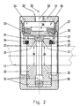
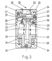
- Dispositif de blocage comprenant deux mâchoires de serrage (33) disposées symétriquement l'une de l'autre, dont chacune est munie d'une ouverture de passage (38) pour une tige, un arbre ou un axe (12) qui la traverse, au moins une protubérance d'actionnement mobile (30), destinée à attaquer entre les mâchoires de serrage (33) à l'encontre de la force d'au moins un ressort (36, 39) qui presse les mâchoires de serrage l'une sur l'autre, autour d'une articulation de basculement (35, 40) pour les placer dans une première position qui ne libère pas la tige, la protubérance d'actionnement étant actionnée pour éloigner les mâchoires de serrage l'une de l'autre en les plaçant dans une deuxième position qui libère la tige, le centre de chaque ouverture de passage (38) se trouvant à une première distance de l'articulation de basculement (35, 40) et à une deuxième distance de la région de l'attaque de la protubérance d'actionnement (30) sur chaque mâchoire de serrage (33), caractérisé en ce que la deuxième distance est plus petite que la première distance, en ce que la protubérance d'actionnement est mise en mouvement au moyen d'un piston d'actionnement (27) qui peut être actionné dans une chambre de piston au moyen d'un fluide, et en ce qu'au moins un ressort est placé au moins partiellement autour des deux mâchoires de serrage.
- Dispositif selon la revendication 1, caractérisé en ce que le piston d'actionnement (27) présente sur son côté qui est éloigné de la chambre de piston un plan d'appui (29) qui s'étend transversalement à la direction de sa course, en ce que, sur sa face arrière dirigée vers le plan d'appui (29), la protubérance d'actionnement (30) est de forme plate et est appuyée sur le plan d'appui en flottement libre, et en ce que les deux mâchoires de serrage (33) sont pressées l'une vers l'autre par la force du ressort.
- Dispositif selon la revendication 2, caractérisé en ce que le plan d'appui (29) s'étend perpendiculairement à la direction de la course.
- Dispositif selon la revendication 2 ou 3, caractérisé en ce que la face arrière, de forme plane, de la protubérance d'actionnement (30) s'étend perpendiculairement à la direction de la course du piston d'actionnement (27).
- Dispositif selon la revendication 1, caractérisé en ce que le piston d'actionnement (27) est réalisé en une seule pièce avec la protubérance d'actionnement.
- Dispositif selon la revendication 1, caractérisé en ce que le ressort est placé autour des deux mâchoires de serrage (33) dans la région de la protubérance d'actionnement (30) et/ou dans la région de l'articulation de basculement (35, 40).
- Dispositif selon une des revendications 1 à 6, caractérisé en ce que le ressort (36, 39) est constitué par une bague torique (36) ou par un cylindre creux (39) et comprend une matière plastique, de préférence du polyuréthane ou en ce que le ressort est constitué par un anneau fendu en acier et est de préférence de forme circulaire en section transversale, ou en ce que le ressort est constitué par un anneau entièrement fermé.
- Dispositif selon la revendication 7, caractérisé en ce que le ressort, constitué par un anneau entièrement fermé, est emboíté dans une rainure circonférentielle (37) des deux mâchoires de serrage (33).
- Dispositif selon une des revendications 1 à 7, caractérisé en ce que la protubérance d'actionnement (30) est constituée par un doigt divisé selon son axe longitudinal.
- Dispositif selon la revendication 9, caractérisé en ce que le doigt divisé (30) est divisé en deux moitiés.
- Dispositif selon une des revendications 1 à 10, caractérisé en ce que le piston d'actionnement est divisé en deux parties transversalement à la direction de sa course, avec formation d'un élément d'actionnement (28) appuyé librement sur son élément de course (27), et l'élément d'actionnement (28) est de forme plate sur sa face arrière et s'appuie en flottant sur une face avant également plate de l'élément de course (27).
- Dispositif selon la revendication 11, caractérisé en ce que l'élément d'actionnement (28) présente la protubérance d'actionnement (30) sur son côté éloigné de l'élément de course (27).
- Dispositif selon une des revendications 1 à 12, caractérisé en ce que l'élément d'actionnement (28) est constitué par un couvercle en forme de U en section transversale, dont la face arrière est plane.
- Dispositif selon la revendication 13, caractérisé en ce que le couvercle (28) emboíte le ressort (36) disposé aux extrémités des mâchoires de serrage (33).
- Dispositif selon une des revendications 1 à 14, caractérisé en ce que la protubérance d'actionnement (30) de l'élément d'actionnement (28) coopère avec des surfaces de commande chanfreinées (31) des mâchoires de serrage (33).
- Dispositif selon une des revendications 1 à 15, caractérisé en ce que les deux mâchoires de serrage (33) présentent, comme articulation de basculement à leur extrémité éloignée de l'élément d'actionnement (28), une tige entretoise (35) qui est fixée à une douille (21).
- Dispositif selon la revendication 16, caractérisé en ce que, dans la douille est prévue, sur le côté éloigné du piston d'actionnement, une cavité servant d'articulation de basculement pour les deux mâchoires de serrage (33).
- Dispositif selon une des revendications 1 à 17, caractérisé en ce qu'au moins deux autres mâchoires de serrage (330) sont prévues entre les deux mâchoires de serrage (33) et en ce que ces mâchoires de serrage intérieures (330) présentent des ouvertures de passage intérieures (380) pour l'axe ou arbre (12), qui sont alignées sur les ouvertures de passage (38), et peuvent être basculées, autour d'une articulation de basculement intérieure, d'une position d'écartement intérieure à une position de proximité intérieure, la position d'écartement intérieure et la position de proximité intérieure servant respectivement de position de blocage qui fixe l'axe (12) aux mâchoires de serrage intérieures (330) en agissant par action de force, et de position de libération qui admet le déplacement de l'axe (12) dans les ouvertures de passage intérieures (380), ou inversement.
- Dispositif de blocage selon la revendication 18, caractérisé en ce que la commande des mâchoires de serrage intérieures (330) est assurée par les mâchoires de serrage (33).
- Dispositif de blocage selon la revendication 18, caractérisé en ce que la commande des mâchoires de serrage (33) est assurée par les mâchoires de serrage intérieures (330).
- Dispositif de blocage selon une des revendications 19 ou 20, caractérisé en ce que les mâchoires de serrage (30) sont en liaison par action de force avec les mâchoires de serrage intérieures (330) qui leur sont respectivement associées.
- Dispositif de blocage selon une des revendications 19 à 21, caractérisé en ce que l'immobilisation par action de force de l'axe (12) est réalisée avec les mâchoires de serrage (30) et qu'elle est réalisée par frottement avec les mâchoires de serrage intérieures (330) dans la position de blocage.
- Utilisation d'un dispositif de blocage selon une des revendications 1 à 22 dans le cas d'un cylindre compact (10).
- Utilisation selon la revendication 23, caractérisée en ce que le corps (11) du cylindre compact (10) présente un évidement (13) adapté à la forme du manchon (21), pour recevoir le dispositif de blocage (20).
- Dispositif selon la revendication 1, caractérisé en ce que le bord de chaque ouverture de passage (38) entre en contact avec la tige (26) sous l'effet du ressort et, en présence d'un mouvement de cette tige, met cette dernière dans une position d'arrêt autobloquante.
Applications Claiming Priority (11)
| Application Number | Priority Date | Filing Date | Title |
|---|---|---|---|
| DE19803214 | 1998-01-28 | ||
| DE19803214 | 1998-01-28 | ||
| DE19833483 | 1998-07-26 | ||
| DE19833483 | 1998-07-26 | ||
| DE29814483U | 1998-08-12 | ||
| DE29814483 | 1998-08-12 | ||
| DE19846187 | 1998-10-07 | ||
| DE19846187A DE19846187A1 (de) | 1998-01-28 | 1998-10-07 | Feststelleinrichtung |
| DE19849990 | 1998-10-29 | ||
| DE19849990 | 1998-10-29 | ||
| PCT/EP1998/007704 WO1999038645A1 (fr) | 1998-01-28 | 1998-11-29 | Dispositif de fixation |
Publications (2)
| Publication Number | Publication Date |
|---|---|
| EP1054750A1 EP1054750A1 (fr) | 2000-11-29 |
| EP1054750B1 true EP1054750B1 (fr) | 2002-01-23 |
Family
ID=27512627
Family Applications (1)
| Application Number | Title | Priority Date | Filing Date |
|---|---|---|---|
| EP98965198A Expired - Lifetime EP1054750B1 (fr) | 1998-01-28 | 1998-11-29 | Dispositif de fixation |
Country Status (8)
| Country | Link |
|---|---|
| US (1) | US6511255B1 (fr) |
| EP (1) | EP1054750B1 (fr) |
| JP (1) | JP2002502014A (fr) |
| AT (1) | ATE212271T1 (fr) |
| CA (1) | CA2312986A1 (fr) |
| DE (1) | DE29821271U1 (fr) |
| HU (1) | HU222546B1 (fr) |
| WO (1) | WO1999038645A1 (fr) |
Families Citing this family (9)
| Publication number | Priority date | Publication date | Assignee | Title |
|---|---|---|---|---|
| EP1284172A1 (fr) * | 2001-08-13 | 2003-02-19 | P W B Ag | Dispositif de fixation pour une unité de mouvement linéaire |
| EP1284171A1 (fr) * | 2001-08-13 | 2003-02-19 | P W B Ag | Dispositif de fixation pour une unité de mouvement linéaire |
| JP4246234B2 (ja) * | 2004-03-24 | 2009-04-02 | 株式会社コガネイ | 流体圧シリンダ |
| CA2499162A1 (fr) * | 2005-03-02 | 2006-09-02 | 1642798 Ontario Inc. | Pince electromagnetique pour la prehension d'un arbre |
| US8087845B2 (en) * | 2008-05-22 | 2012-01-03 | GM Global Technology Operations LLC | Integrated locking assembly for reconfigurable end-effectors |
| US8702340B2 (en) * | 2010-01-27 | 2014-04-22 | GM Global Technology Operations LLC | Integrated linear and rotary locking device |
| DE102010022747A1 (de) | 2010-06-04 | 2011-12-08 | Wabco Gmbh | Einrichtung mit einem pneumatischen Stellzylinder und Verfahren zur Steuerung einer solchen Einrichtung |
| CN103644270A (zh) | 2012-06-15 | 2014-03-19 | Tse制动器股份有限公司 | 用于气动执行器的偏转弹簧 |
| CN104061206A (zh) * | 2014-04-28 | 2014-09-24 | 宁波亚德客自动化工业有限公司 | 一种抱紧缸 |
Family Cites Families (7)
| Publication number | Priority date | Publication date | Assignee | Title |
|---|---|---|---|---|
| US2806723A (en) * | 1955-06-16 | 1957-09-17 | Thomas H Fairclough | Telescopic support device |
| DE2719822A1 (de) * | 1977-05-04 | 1979-02-01 | Volkswagenwerk Ag | Klemmvorrichtung |
| US4214795A (en) * | 1977-11-25 | 1980-07-29 | Shoketsu Kinzoku Kogyo Kabushiki Kaisha | Piston braking device for hydraulic or pneumatic cylinders |
| US4564088A (en) * | 1984-01-09 | 1986-01-14 | Kyoho Machine Works, Ltd. | Axial braking device |
| DE4012524A1 (de) * | 1990-04-19 | 1991-10-24 | Doma Tech Pneumatische Kompone | Feststellvorrichtung fuer eine linearbewegungseinheit |
| EP0753670B1 (fr) * | 1995-01-31 | 2000-11-02 | Pubot Giken Co., Ltd. | Systeme de freinage pour corps a deplacement lineaire |
| CH689114A5 (de) * | 1996-08-23 | 1998-10-15 | Pwb Ag | Feststellvorrichtung einer Linearbewegungseinheit. |
-
1998
- 1998-11-29 HU HU0102679A patent/HU222546B1/hu not_active IP Right Cessation
- 1998-11-29 WO PCT/EP1998/007704 patent/WO1999038645A1/fr active IP Right Grant
- 1998-11-29 EP EP98965198A patent/EP1054750B1/fr not_active Expired - Lifetime
- 1998-11-29 DE DE29821271U patent/DE29821271U1/de not_active Expired - Lifetime
- 1998-11-29 JP JP2000529923A patent/JP2002502014A/ja active Pending
- 1998-11-29 US US09/600,262 patent/US6511255B1/en not_active Expired - Fee Related
- 1998-11-29 CA CA002312986A patent/CA2312986A1/fr not_active Abandoned
- 1998-11-29 AT AT98965198T patent/ATE212271T1/de not_active IP Right Cessation
Also Published As
| Publication number | Publication date |
|---|---|
| DE29821271U1 (de) | 1999-09-02 |
| WO1999038645A1 (fr) | 1999-08-05 |
| US6511255B1 (en) | 2003-01-28 |
| ATE212271T1 (de) | 2002-02-15 |
| HU222546B1 (hu) | 2003-08-28 |
| HUP0102679A2 (hu) | 2002-01-28 |
| JP2002502014A (ja) | 2002-01-22 |
| EP1054750A1 (fr) | 2000-11-29 |
| HUP0102679A3 (en) | 2002-02-28 |
| CA2312986A1 (fr) | 1999-08-05 |
Similar Documents
| Publication | Publication Date | Title |
|---|---|---|
| DE4430258C1 (de) | Zuspannvorrichtung für eine Scheibenbremse | |
| DE2334091C3 (de) | Selbstlösend wirkende Teilbelagscheibenbremse | |
| EP1054750B1 (fr) | Dispositif de fixation | |
| EP0786952A1 (fr) | Support de siege pour chaises de bureau ou analogue | |
| DE3403297C2 (fr) | ||
| DE2718003C2 (de) | Scheibenbremse für Fahrzeuge, insbesondere Straßenfahrzeuge | |
| DE2205880A1 (de) | Traeger fuer mikroskope | |
| DE2753875C2 (de) | Führung für eine Schwimmsattel-Teilbelag-Scheibenbremse auf einem Bremsträger | |
| DE2220483C3 (de) | Mechanische Betätigungsvorrichtung für eine Innenbacken-Trommelbremse | |
| EP0137431B1 (fr) | Frein à sabot pour véhicule ferroviaire | |
| DE19823016C1 (de) | Scheibenbremse für ein Landfahrzeug | |
| DE19917097A1 (de) | Feststelleinrichtung | |
| EP0480366A1 (fr) | Frein à disque à étrier coulissant | |
| DE4407293C1 (de) | Bremszange für Scheibenbremsen von Schienenfahrzeugen | |
| DE19934750A1 (de) | Feststelleinrichtung | |
| DE19846187A1 (de) | Feststelleinrichtung | |
| DE904265C (de) | Zentrier- und Nachstellvorrichtung fuer selbstverstaerkend wirkende Innenbackenbremsen an Kraftfahrzeugen | |
| DE2741707C2 (de) | Halterungsvorrichtung für eine Bremsbacke in einer Scheibenbremse | |
| DE202018005634U1 (de) | Feststelleinrichtung | |
| DE2805147C2 (fr) | ||
| DE1555529C3 (de) | Käfig mit Ausnehmungen zur Führung der Rollen einer Fahrzeugbremsbetätigungsvorrichtung | |
| DE102017114356B4 (de) | Schwenkeinheit zum Schwenken von Anbauteilen oder Werkstücken | |
| DE2366135C2 (de) | Spreizkeil-Betätigungsvorrichtung für Innenbackenbremsen | |
| DE1809460B2 (de) | Türfeststeller, insbesondere für Kraftwagentüren | |
| DE2208251C3 (de) | Scheibenbremse fur Schienenfahrzeuge |
Legal Events
| Date | Code | Title | Description |
|---|---|---|---|
| PUAI | Public reference made under article 153(3) epc to a published international application that has entered the european phase |
Free format text: ORIGINAL CODE: 0009012 |
|
| 17P | Request for examination filed |
Effective date: 20000726 |
|
| AK | Designated contracting states |
Kind code of ref document: A1 Designated state(s): AT CH DE FR GB IT LI SE |
|
| 17Q | First examination report despatched |
Effective date: 20001220 |
|
| GRAG | Despatch of communication of intention to grant |
Free format text: ORIGINAL CODE: EPIDOS AGRA |
|
| GRAG | Despatch of communication of intention to grant |
Free format text: ORIGINAL CODE: EPIDOS AGRA |
|
| GRAH | Despatch of communication of intention to grant a patent |
Free format text: ORIGINAL CODE: EPIDOS IGRA |
|
| GRAH | Despatch of communication of intention to grant a patent |
Free format text: ORIGINAL CODE: EPIDOS IGRA |
|
| GRAA | (expected) grant |
Free format text: ORIGINAL CODE: 0009210 |
|
| REG | Reference to a national code |
Ref country code: GB Ref legal event code: IF02 |
|
| AK | Designated contracting states |
Kind code of ref document: B1 Designated state(s): AT CH DE FR GB IT LI SE |
|
| REF | Corresponds to: |
Ref document number: 212271 Country of ref document: AT Date of ref document: 20020215 Kind code of ref document: T |
|
| REG | Reference to a national code |
Ref country code: CH Ref legal event code: EP |
|
| REF | Corresponds to: |
Ref document number: 59802928 Country of ref document: DE Date of ref document: 20020314 |
|
| GBT | Gb: translation of ep patent filed (gb section 77(6)(a)/1977) |
Effective date: 20020407 |
|
| ET | Fr: translation filed | ||
| PLBE | No opposition filed within time limit |
Free format text: ORIGINAL CODE: 0009261 |
|
| STAA | Information on the status of an ep patent application or granted ep patent |
Free format text: STATUS: NO OPPOSITION FILED WITHIN TIME LIMIT |
|
| 26N | No opposition filed | ||
| REG | Reference to a national code |
Ref country code: CH Ref legal event code: NV Representative=s name: SAEGER & PARTNER |
|
| PGFP | Annual fee paid to national office [announced via postgrant information from national office to epo] |
Ref country code: AT Payment date: 20071123 Year of fee payment: 10 |
|
| PGFP | Annual fee paid to national office [announced via postgrant information from national office to epo] |
Ref country code: SE Payment date: 20071126 Year of fee payment: 10 |
|
| REG | Reference to a national code |
Ref country code: CH Ref legal event code: PCAR Free format text: MANFRED SAEGER;POSTFACH 5;7304 MAIENFELD (CH) |
|
| EUG | Se: european patent has lapsed | ||
| PG25 | Lapsed in a contracting state [announced via postgrant information from national office to epo] |
Ref country code: AT Free format text: LAPSE BECAUSE OF NON-PAYMENT OF DUE FEES Effective date: 20081129 |
|
| REG | Reference to a national code |
Ref country code: CH Ref legal event code: PFA Owner name: FRENOTECH ESTABLISHMENT Free format text: FRENOTECH ESTABLISHMENT#ZOLLSTRASSE 35, POSTFACH 444#9494 SCHAAN (LI) -TRANSFER TO- FRENOTECH ESTABLISHMENT#ZOLLSTRASSE 35, POSTFACH 444#9494 SCHAAN (LI) |
|
| PGFP | Annual fee paid to national office [announced via postgrant information from national office to epo] |
Ref country code: CH Payment date: 20090901 Year of fee payment: 12 |
|
| PGFP | Annual fee paid to national office [announced via postgrant information from national office to epo] |
Ref country code: DE Payment date: 20090918 Year of fee payment: 12 |
|
| PGFP | Annual fee paid to national office [announced via postgrant information from national office to epo] |
Ref country code: IT Payment date: 20091127 Year of fee payment: 12 Ref country code: GB Payment date: 20091123 Year of fee payment: 12 Ref country code: FR Payment date: 20091202 Year of fee payment: 12 |
|
| PG25 | Lapsed in a contracting state [announced via postgrant information from national office to epo] |
Ref country code: SE Free format text: LAPSE BECAUSE OF NON-PAYMENT OF DUE FEES Effective date: 20081130 |
|
| REG | Reference to a national code |
Ref country code: CH Ref legal event code: PL |
|
| GBPC | Gb: european patent ceased through non-payment of renewal fee |
Effective date: 20101129 |
|
| PG25 | Lapsed in a contracting state [announced via postgrant information from national office to epo] |
Ref country code: CH Free format text: LAPSE BECAUSE OF NON-PAYMENT OF DUE FEES Effective date: 20101130 Ref country code: LI Free format text: LAPSE BECAUSE OF NON-PAYMENT OF DUE FEES Effective date: 20101130 |
|
| REG | Reference to a national code |
Ref country code: FR Ref legal event code: ST Effective date: 20110801 |
|
| REG | Reference to a national code |
Ref country code: DE Ref legal event code: R119 Ref document number: 59802928 Country of ref document: DE Effective date: 20110601 Ref country code: DE Ref legal event code: R119 Ref document number: 59802928 Country of ref document: DE Effective date: 20110531 |
|
| PG25 | Lapsed in a contracting state [announced via postgrant information from national office to epo] |
Ref country code: DE Free format text: LAPSE BECAUSE OF NON-PAYMENT OF DUE FEES Effective date: 20110531 |
|
| PG25 | Lapsed in a contracting state [announced via postgrant information from national office to epo] |
Ref country code: FR Free format text: LAPSE BECAUSE OF NON-PAYMENT OF DUE FEES Effective date: 20101130 |
|
| PG25 | Lapsed in a contracting state [announced via postgrant information from national office to epo] |
Ref country code: GB Free format text: LAPSE BECAUSE OF NON-PAYMENT OF DUE FEES Effective date: 20101129 |
|
| PG25 | Lapsed in a contracting state [announced via postgrant information from national office to epo] |
Ref country code: IT Free format text: LAPSE BECAUSE OF NON-PAYMENT OF DUE FEES Effective date: 20101129 |