EP1054217B1 - Method for making a under floor heating and heating element support plate for carrying out the method - Google Patents
Method for making a under floor heating and heating element support plate for carrying out the method Download PDFInfo
- Publication number
- EP1054217B1 EP1054217B1 EP00110085A EP00110085A EP1054217B1 EP 1054217 B1 EP1054217 B1 EP 1054217B1 EP 00110085 A EP00110085 A EP 00110085A EP 00110085 A EP00110085 A EP 00110085A EP 1054217 B1 EP1054217 B1 EP 1054217B1
- Authority
- EP
- European Patent Office
- Prior art keywords
- heating element
- heating
- support plate
- element support
- layer
- Prior art date
- Legal status (The legal status is an assumption and is not a legal conclusion. Google has not performed a legal analysis and makes no representation as to the accuracy of the status listed.)
- Expired - Lifetime
Links
Images


Classifications
-
- F—MECHANICAL ENGINEERING; LIGHTING; HEATING; WEAPONS; BLASTING
- F24—HEATING; RANGES; VENTILATING
- F24D—DOMESTIC- OR SPACE-HEATING SYSTEMS, e.g. CENTRAL HEATING SYSTEMS; DOMESTIC HOT-WATER SUPPLY SYSTEMS; ELEMENTS OR COMPONENTS THEREFOR
- F24D3/00—Hot-water central heating systems
- F24D3/12—Tube and panel arrangements for ceiling, wall, or underfloor heating
- F24D3/14—Tube and panel arrangements for ceiling, wall, or underfloor heating incorporated in a ceiling, wall or floor
- F24D3/141—Tube mountings specially adapted therefor
- F24D3/142—Tube mountings specially adapted therefor integrated in prefab construction elements
-
- Y—GENERAL TAGGING OF NEW TECHNOLOGICAL DEVELOPMENTS; GENERAL TAGGING OF CROSS-SECTIONAL TECHNOLOGIES SPANNING OVER SEVERAL SECTIONS OF THE IPC; TECHNICAL SUBJECTS COVERED BY FORMER USPC CROSS-REFERENCE ART COLLECTIONS [XRACs] AND DIGESTS
- Y02—TECHNOLOGIES OR APPLICATIONS FOR MITIGATION OR ADAPTATION AGAINST CLIMATE CHANGE
- Y02B—CLIMATE CHANGE MITIGATION TECHNOLOGIES RELATED TO BUILDINGS, e.g. HOUSING, HOUSE APPLIANCES OR RELATED END-USER APPLICATIONS
- Y02B30/00—Energy efficient heating, ventilation or air conditioning [HVAC]
Definitions
- the invention relates to a Walkerelementismeplatte, the is assignable with a strand-shaped heating element and the consists of a plastic foam board, on at least one Surface side with a reinforced hardened mortar layer is occupied and from the other flat side with Receiving recesses is provided, in which the heating element can be inserted, wherein the reinforcement of the mortar layer unhurt remains.
- a generic Schutelement disposplatte is from DE 29 802 367 U1 known. After the description of this utility model be in a commercially available polystyrene foam insulation board with double-sided reinforced mortar layer outer layer Profile pits for the inclusion of Cut heating elements.
- a disadvantage of this Thompsonelement disposplatte is for surface heating, however, that the plate is stacked and used as a bulky product with the associated danger of breakage must be transported. On Construction sites and interior fittings often lack the space for stacking such products.
- a suitable building board is known from DE 42 34 269 C1. This is on a flat side of a foam board placed a glass fiber fabric and then a mortar layer applied so that after hardening a reinforced Mortar layer arises. Subsequently, the opposite Flat side to be coated as well. hereby the foam core gets a stiff and reinforced textured Sandwich scaffolding that makes it both heat-stable as well as makes it suitable with cladding panels, so For example, tiles, glued or otherwise to be provided. The element can be plastered, wallpapered or canceled.
- the advantages achieved by the invention are in particular in that by using the building board a low level can be realized.
- the Schuelementingaus traditionsbrook Kunststoffessen Make sure that the heating element is directly under a coating layer runs, so that the heat directly is transferred to the lining layer. This increases the effectiveness of the surface heating very much because non-intervening insulating layers are heated have to. The surface heating also reacts quickly on temperature changes.
- the Wienelementingausnaturalung as a V-shaped Bankelementaus simplifiedung or formed as a polygonal Bankelementsuitausnaturalung be.
- a circular recess as well to look polygonal.
- a foil element can be raised, be glued in particular and then on this the heating element with at least one Befest Trentskrampe, a pipe clip body and / or at least one fastening clip be attached.
- the attachment takes place with appropriate aids such as glue, wires, nails and like.
- a film element On the base element, a film element can be placed and then install the heating element on top of it.
- a film element As a foil element, a film or an insulating film be used with at least one adhesive layer.
- the Schuijnelementaus fundamentalungen can as a linear recess and / or Bogenauslangisme be introduced.
- the introduction Can be done by milling or cutting become. With the help of the recesses it is possible to use the heating element Meandering on the laid plates to lay.
- a heating element As a heating element, a heat cable or a fluid heating tube Find use. This makes it possible to or to realize hot water underfloor heating.
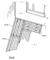
- Fig. 1a the detail of a room is shown, the by at least one wall element 4 and a substructure in Form of a floor element 3 is limited.
- the floor element 3 can be the ceiling of a new building or a existing floor of a building to be renovated be.
- a Building board 10 is used for the Schutlement.platte 1 and the Schuelement disposabschlußplatte 2 .
- This building board exists as Figs. 2 to 9 show, from a rigid foam plate 13, the on one of its flat sides with a reinforced mortar layer 14 is coated.
- the reinforced mortar layer 14 arises from the fact that on the flat side of the foam board 13 stress-free a glass fiber fabric is placed and then the glass fiber fabric with a liquid mortar is covered. Excess liquid mortar is over swept the glass fiber fabric, so that after drying the structure of the glass fiber fabric can be recognized.
- the second flat side of the foam board 13 with another reinforced mortar layer be coated.
- the building panels 10 can after this Manufacturing process in different lengths and Thicknesses are made.
- a foam board 13 in a thickness between 15 and 50 mm, preferably 18 mm, for use.
- Fig. 8 shows a rectangular cross-section KirelementlinearauseWhyung 11 introduced. But it can also be one in cross section truncated pyramidal SchuelementlinearauseWhyung 11 'are introduced into the rigid foam plate 13.
- Fig. 9 shows a further embodiment in the form of a triangular heating element linear recess 11 ", this triangular heating element linear recess 11 "may be as V-shaped Schuelementlineausus supraung so far in the foam board 13 are introduced, that it is above the armored Mortar layer 14 ends.
- the building board 10 has not only load-bearing, but also insulating Properties. To get these, the Schuelementaus Principle 11, 11 ', 11 "up to a recess base element 27, the opposite of the armored Mortar layer 14 is spaced. About in the middle the Ausappelungsgrund vomettis 27 until before reinforced mortar layer a vertical recess cut 12 guided along the Schuelementlinearaus Principleung 11, 11 ', 11 "takes place.
- the building board 10 also becomes a Schuelementskyabschlußplatte 2 made. in this connection are in the rigid foam plate 13 Bankelementbogenausappelumble 21 introduced.
- the Schuelementbogenausappelumble are compatible with respect to their configuration KirelementlineausEnglishept 11, 11 ', 11 ". They can therefore rectangular, pyraumidenstumpfförmig or triangular be formed and in a recess base end up. From this recess base surface element 27 go, as shown in FIG. 5, straight through Recess cuts 12, also in the already described Distance a are spaced apart from each other until to the reinforced mortar layer 14 by.
- the SchuelementbogenausEnglishlessness 21 have a radius corresponding to the laying of the Heating element 7 to be observed bending radius R considered. As particularly shown in FIG. 1, are by a Schuelementbogenaus simplifiedung 21 always two Schuelementlinearausnaturalept 11, 11 'or 11 "connected to each other mentions this point that the Schuelementdisposedplatte 1 can be designed as Universalauslegeplatte in the the Schuijnidelineausappelsungen 11, 11 ', 11 "always the have the same distance a from each other.
- the attachment foil element 9 can have an adhesive layer 91. With the help of this Adhesive layer 91, the film 9 is glued. Insertion of the top film element 9 can already at the Production of the plates 1 and 2 done. The attachment foil element 9 is also in this case at the introduction of the recess section 12 with severed. The film 9 but can also be glued on the site. She may be on the opposite side with another Adhesive layer 92 are provided. With the help of this adhesive layer then the heating element can be attached. Instead of but it can also be the entire surface instead of with a reinforced mortar layer with a heat-reflecting Layer be provided.
- FIGS. 6 and 7 Two further attachment possibilities of the heating element 7 are shown in FIGS. 6 and 7.
- the heating element 7 is held with a Befest Trentskrampe 8 in the SchuLainskyung or in the Schuelementbogenaus principlesung.
- the staple 8 is similar to a staple used for attaching fence wire to wooden posts.
- the fastening variant with the aid of the fastening clip 8 ' makes use of the softness and stability of the side walls of the heating element linear recesses or heating element arch recesses.
- the mounting clip 8 ' is made of an elastic material, which may be steel or plastic. It is held together on the sides and released when inserting the heating element 7, so that the ends can drill into the soft foam plate 13.
- the fluid may be oil or water. comes water or water with additives as heat carrier, creates a hot water underfloor heating.
- the fluid heating pipes can be made of copper or plastic be.
- Heat cable 7 is used.
- the heat cable 7 consists of resistance wires, which are surrounded by an isolation.
- plastic jacket Both plastic coats exist made of a PEX plastic.
- To the other plastic jacket is a layer of zinc contact with copper wires laid.
- the outer jacket of the cable is a PVC jacket.
- the heat cable 7 is made of the PVC outer jacket covering the tin layer with the copper wires envelops. Under the tin layer lies with the copper wires Another insulating jacket made of a HDPE plastic, the wrapped another tin coat with copper wires. The Copper wires spin around the tin layer in both cases. Under the second tin-copper layer is another Plastic jacket made of a HDPE plastic, which is a Teflon-PCFE jacket envelops. The Teflon PCFE sheath envelops one Cable core made of copper or aluminum. With the conventional Heating cable can reach a maximum temperature of 125 ° and with the Multiflex heating cable a maximum temperature of 260 ° are generated.
- the temperature on max. 60 ° C limited and regulated accordingly.
- This heat cable is manufactured under the name EBECO and is available in different lengths.
- the both versions of the described heating cable as a heat cable 7 is that the heat evenly over the Length is generated distributed. So is the resistance at a 5 or 6 m long heat cable about 140 ohms per meter and reaches graded up to 100 or 165 m at 0.18 to 0.25 ohms per meter at about 2000 watts.
- Fig. 13a the insert is shown in a large kitchen. In commercial kitchens must for many people eat at fixed times which is still hot at these times.
- a hearth 32 are constructed on a substructure in the form of a table 31st or similar heat plates 30 used in the vicinity a hearth 32 are constructed.
- the heat retaining plate 30 is in this case using the Schuelementziplatte 1, which is fixed to the table 31 becomes.
- the SchuelementlinearausEnglishstead 11 laid the heat cable 7 or a fluid heating tube.
- the Schuelementliniplatte 1 is here as well as at a floor heating on both sides with the Schuelement disposabschlußplatte 2 provided so that the heat cable. 7 meandering can be laid. Is the heat cable 7 laid, are then tiles 6 'on the foam board 13 glued. Instead of the tiles 6 'can also be a continuous stone plate or metal plate are used.
- Fig. 1b the structure of a surface heating with Schuelementlicplatten 20 is shown.
- a section a space represented by at least one wall element 4 and a substructure in the form of a foot member 3 limited is.
- a window 40 is inserted in the wall 4, a window 40 is inserted.
- the floor element can also be the ceiling of a new building or an existing floor of a to be renovated Be a building.
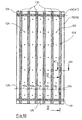
- the Schuelementismeplatte 20 is a building board, consisting of the rigid foam plate 13, which on both sides with a reinforced mortar layer 14 is provided. She has a Width of 600 mm and a length of 1200 mm. Your thickness is shown in FIG. 11 and 12 20 mm.
- the first and the last long heating element trench recess 131 is up to the edge of Hammerelement disposing 20 in one Borelement fortune-endabstand 125 introduced, the half way long is like the distance 124. The same applies to the two transverse Hammerelementgrabenausappel undertaken 131st
- the Entdampfungsausappellus 122 are designed as round holes, the one Diameter of about 10 mm.
- the tube clip body 126 has a clip body foot 127. This is plate-shaped. On the clip body foot are two opposing clip-clasp body 129th arranged. On both sides of the Klipspangen stressess are Foot recesses 128 are introduced into the clip body foot. The Foot recesses are formed as round holes.
- the heating element 7 is in this case, the heat cable 7, its structure already in detail was explained. It becomes clear that the distances the adjacent heat cable 7 different can be chosen. Especially in the area of the window 40, the heat cable is laid close to each other. hereby is assured that such cold spots or cold concentration points especially taken into account in a room can be. The cold that penetrates from the outside becomes one opposed to effective heat veiling that ensures that the room behind it is evenly warmed up becomes. Also other locations in the room can be dense laid heat cable 7 are provided.
- Another advantage is that with wet floor elements the Entdampfungsaus Principleungen 122 as "chimneys” Act. The moisture evaporating through the heat becomes purposefully passed through the building board and can practice the grout between the tiles to the outside reach. If the devolatilizing recesses 122 were not present, Although the moisture could evaporate, could but do not get outside under the sealing building board. The evaporated moisture penetrates in this case in the floor element 3 and in the reinforced mortar layer 14 and leads to their destruction.
- Another advantage is that the heat cable 7 according to its resistance values is laid with a specified length. Of the Connection of the heat cable 7 takes place at a certain Job already set. The lead out a variety of connection cable or taking into account a large number of connection points deleted.
- Fig. 13b is the use of Bank 1 of the Heat cable 7 presented in the canteen kitchen. This is on the table 31 near the hearth 32, the heater support plate 20 hung up. It is adapted in its dimensions to the table 31. By choosing the Bankungsaus Principleungsabmix 124, the Heat cable 7 are laid differently. The pipe clip body 126 ensure that the heat cable laid in loops 7 is kept effective.
Landscapes
- Engineering & Computer Science (AREA)
- Physics & Mathematics (AREA)
- Thermal Sciences (AREA)
- Chemical & Material Sciences (AREA)
- Combustion & Propulsion (AREA)
- Mechanical Engineering (AREA)
- General Engineering & Computer Science (AREA)
- Central Heating Systems (AREA)
- Floor Finish (AREA)
- Resistance Heating (AREA)
- Diaphragms For Electromechanical Transducers (AREA)
- Surface Heating Bodies (AREA)
Abstract
Description
Die Erfindung betrifft eine Heizelementträgerplatte, die mit einem strangförmigen Heizelement belegbar ist und die aus einer Kunststoff-Hartschaumplatte besteht, die auf wenigstens einer Flächenseite mit einer armierten ausgehärteten Mörtelschicht belegt ist und von der anderen Flachseite her mit Aufnahmeausnehmungen versehen ist, in die das Heizelement einlegbar ist, wobei die Armierung der Mörtelschicht unverletzt bleibt.The invention relates to a Heizelementträgerplatte, the is assignable with a strand-shaped heating element and the consists of a plastic foam board, on at least one Surface side with a reinforced hardened mortar layer is occupied and from the other flat side with Receiving recesses is provided, in which the heating element can be inserted, wherein the reinforcement of the mortar layer unhurt remains.
Eine gattungsgemäße Heizelementträgerplatte ist aus DE 29 802 367 U1 bekannt. Nach der Beschreibung zu diesem Gebrauchsmuster werden in einer handelsübliche Polystyrol-Hartschaumdämmplatte mit beidseitiger armierter Mörtelschicht-Außenlage Profil-Vertiefungen für die Aufnahme von Heizelementen eingeschnitten. Nachteilig bei dieser Heizelementträgerplatte ist für Flächenheizungen allerdings, dass die Platte gestapelt und als sperriges Produkt mit der damit verbundenen Bruchgefahr transportiert werden muß. Auf Baustellen und bei Innenausbauten fehlt oftmals der Platz zur Stapelung derartiger Produkte.A generic Heizelementträgerplatte is from DE 29 802 367 U1 known. After the description of this utility model be in a commercially available polystyrene foam insulation board with double-sided reinforced mortar layer outer layer Profile pits for the inclusion of Cut heating elements. A disadvantage of this Heizelementträgerplatte is for surface heating, however, that the plate is stacked and used as a bulky product with the associated danger of breakage must be transported. On Construction sites and interior fittings often lack the space for stacking such products.
Eine geeignete Bauplatte ist aus der DE 42 34 269 C1 bekannt. Hierbei wird auf einer Flachseite einer Hartschaumplatte ein Glasfasergewebe aufgelegt und dann eine Mörtelschicht so aufgetragen, daß nach dem Aushärten eine armierte Mörtelschicht entsteht. Anschließend kann die gegenüberliegende Flachseite ebenso beschichtet werden. Hierdurch erhält der Schaumstoffkern ein steifes und armiert strukturiertes Sandwich-Gerüst, das ihn sowohl wärmestabil macht, als auch dazu geeignet macht, mit Verkleidungsplatten, also beispielsweise Fliesen, beklebt oder in sonstiger Weise versehen zu werden. Das Element kann verputzt, tapeziert oder gestrichen werden.A suitable building board is known from DE 42 34 269 C1. This is on a flat side of a foam board placed a glass fiber fabric and then a mortar layer applied so that after hardening a reinforced Mortar layer arises. Subsequently, the opposite Flat side to be coated as well. hereby the foam core gets a stiff and reinforced textured Sandwich scaffolding that makes it both heat-stable as well as makes it suitable with cladding panels, so For example, tiles, glued or otherwise to be provided. The element can be plastered, wallpapered or canceled.
Es stellt sich demnach die Aufgabe, ausgehend von einer Bauplatte aus Polystyrol-Hartschaum mit Mörtelbeschichtung, eine für den Transport und die Bereithaltung vereinfachte Platte zu konzipieren.It is therefore the task, starting from a Building board made of polystyrene foam with mortar coating, one simplified for transport and availability To design plate.
Diese Aufgabe wird gelöst durch eine Heizelementträgerplatte der eingangs genannten Art, bei der von der Sohle der Aufnahmeausnehmungen bis zur armierten Mörtelschicht Ausnehmungsschnitte durch die Hartschaumplatte geführt sind, so dass die Heizelementträgerplatte zu einer Rolle aufrollbar ist.This object is achieved by a Heizelementträgerplatte of the type mentioned, in which from the sole of the Receiving recesses up to the reinforced mortar layer recess cuts are guided through the hard foam board, so that the Heizelementträgerplatte rollable into a roll is.
An sich ist eine Verlegebasis für Fußbodenheizungsrohre in Form einer rollbaren Einheit bekannt. Die Schrift EP 0 606 789 A1 zeigt ein Fußbodenheizungssystem, das eine rollbare Dämm- und Verlegematte aus Polystyrolschaum einsetzt. Die Matte sitzt Noppen und ist im wesentlichen einschichtig aufgebaut. Nachteilig ist, daß nach dem Verlegen der Heizungsrohre eine dicke Estrichschicht aufgetragen werden muß, auf die erst nach deren Aushärten ein Belag verlegt werden kann und daß die Vorteile einer an sich bekannten Bauplatte aus Polystrol-Hartschaum, wie Verfügbarkeit, Preiswürdigkeit und Verarbeitbarkeit mit verschiedenen Belägen, nicht genutzt werden. In itself is a laying base for floor heating pipes in Form of a rollable unit known. The document EP 0 606 789 A1 shows a floor heating system that is a rollable Insulation and installation mat made of polystyrene foam. The Mat sits pimples and is essentially single-layered built up. The disadvantage is that after laying the heating pipes a thick layer of screed is applied must be laid on the only after their curing a surface can be and that the advantages of a known Building board made of polystyrene hard foam, such as availability, Value for money and processability with different coverings, not used.
Die mit der Erfindung erzielten Vorteile bestehen insbesondere darin, daß sich durch die Verwendung der Bauplatte eine geringe Bauhöhe realisieren läßt. Die Heizelementaufnahmeausnehmungen sorgen dafür, daß das Heizelement direkt unter einer Belagschicht verläuft, so daß die Wärme direkt auf die Belagschicht übertragen wird. Hierdurch erhöht sich die Effektivität der Flächenheizung ganz wesentlich, da nicht dazwischenliegende Isolierschichten aufgeheizt werden müssen. Die Flächenheizung reagiert darüber hinaus schnell auf Temperaturänderungen.The advantages achieved by the invention are in particular in that by using the building board a low level can be realized. The Heizelementaufnahmeausnehmungen Make sure that the heating element is directly under a coating layer runs, so that the heat directly is transferred to the lining layer. This increases the effectiveness of the surface heating very much because non-intervening insulating layers are heated have to. The surface heating also reacts quickly on temperature changes.
Für die Aufnahme der Heizelemente kann die Heizelementaufnahmeausnehmung als V-förmige Heizelementausnehmung oder als mehreckförmige Heizelementaufnahmeausnehmung ausgebildet sein. Hierbei ist eine kreisförmige Ausnehmung auch als mehreckige anzusehen.For receiving the heating elements, the Heizelementaufnahmeausnehmung as a V-shaped Heizelementausnehmung or formed as a polygonal Heizelementaufnahmeausnehmung be. Here is a circular recess as well to look polygonal.
Die unterschiedlich gestalteten Heizelementaufnahmeausnehmungen können bis zu einem gegenüber der armierten Mörtelschicht beabstandeten Grundflächenelement eingebracht werden. Unterhalb dieses Flächenelementes, d.h. von der Sohle der Aufnahmeausnehmung bis zur armierten Mörtelschicht, ist in die Hartschaumplatte ein Ausnehmungsschnitt eingebracht. Hierdurch ist möglich, die Heizelementträgerplatte ähnlich wie eine Tapetenbahn aufzurollen. Hierdurch wird nicht nur Lagerkapazität, sondern auch Transportraum eingespart. Darüber hinaus läßt sich die Rolle auf der Baustelle wesentlich einfacher auslegen, als große durchgehende Platten.The differently shaped Heizelementaufnahmeausnehmungen can be up to one opposite the reinforced mortar layer spaced base element are introduced. Below this surface element, i. from the sole the receiving recess to the reinforced mortar layer is introduced into the foam plate a recess cut. This makes it possible, the Heizelementträgerplatte similar how to roll up a wallpaper web. This will not only Storage capacity, but also saved transport space. About that In addition, the role on the site can be essential easier to lay out than large, continuous panels.
Durch eingehende Versuche wurde ermittelt, daß die Verwendung einer rechteckförmigen Heizelementausnehmung mit einem sich daran anschließenden Ausnehmungsschnitt bis zur armierten Mörtelschicht am besten für Flächenheizungen verwenden läßt. In-depth testing has determined that the use a rectangular Heizelementausnehmung with a followed by a recess cut to the armored Mortar layer best for surface heating use leaves.
Auf das Grundflächenelement kann ein Folienelement aufgelgt, insbesondere aufgeklebt werden und auf diesem dann das Heizelement mit wenigstens einer Befestigungskrampe, einem Rohrklippkörper und/oder wenigstens einem Befestigungsclip befestigt werden. Die Befestigung erfolgt mit entsprechenden Hilfsmitteln wie Kleber, Drähte, Nägel und dergleichen.On the base element a foil element can be raised, be glued in particular and then on this the heating element with at least one Befestigungskrampe, a pipe clip body and / or at least one fastening clip be attached. The attachment takes place with appropriate aids such as glue, wires, nails and like.
Auf das Grundflächenelement kann ein Folienelement aufgelegt und auf diesem dann das Heizelement installiert werden. Dabei kann als Folienelement eine Folie oder eine Isolierfolie mit wenigstens einer Kleberschicht verwendet werden.On the base element, a film element can be placed and then install the heating element on top of it. In this case, as a foil element, a film or an insulating film be used with at least one adhesive layer.
Die Heizelementausnehmungen können als Linearausnehmung und/oder Bogenausnehmungen eingebracht werden. Das Einbringen kann durch ein Einfräsen bzw. Einschneiden vollzogen werden. Mit Hilfe der Ausnehmungen ist es möglich, das Heizelement mäanderförmig auf den ausgelegten Platten zu verlegen.The Heizelementausnehmungen can as a linear recess and / or Bogenausnehmungen be introduced. The introduction Can be done by milling or cutting become. With the help of the recesses it is possible to use the heating element Meandering on the laid plates to lay.
Als Heizelement kann ein Wärmekabel oder ein Fluid-Heizrohr Verwendung finden. Hierdurch ist es möglich, eine Elektro- oder Warmwasser-Fußbodenheizung zu realisieren.As a heating element, a heat cable or a fluid heating tube Find use. This makes it possible to or to realize hot water underfloor heating.
Die Erfindung ist in der Zeichnung dargestellt und wird im folgenden näher beschrieben. Es zeigen:
- Fig. 1a
- einen ersten Aufbau einer Fußbodenheizung in einer schematischen, perspektivischen, teilgeschnittenen Darstellung,
- Fig. 1b
- einen zweiten Aufbau einer Fußbodenheizung in einer schematischen, perspektivischen, teilgeschnittenen Darstellung,
- Fig. 2
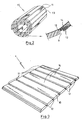
- eine zu einer Trägerelementrolle aufgerollte Heizelementträgerplatte für einen Aufbau einer Fußbodenheizung gemäß Fig. 1a in einer schematischen, perspektivischen Darstellung,
- Fig. 3
- eine zu einer Heizelementträgerplatte ausgelegte Trägerelementrolle gemäß Fig. 2,
- Fig. 4
- einen Schnitt durch einen Aufbau einer Fußbodenheizung gemäß Fig. 1a entlang der Linie IV - IV,
- Fig. 5
- eine ausgelegte Heizelementträgerabschlußplatte für einen Aufbau einer Fußbodenheizung gemäß Fig. 1a in einer schematischen, perspektivischen Darstellung,
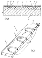
- Fig. 6
- und 7 jeweils einen Ausschnitt aus einer Platte gemäß den Fig. 1a und 2 bis 5 mit einer pyramidenstumpfförmig ausgebildeten Heizelementausnehmung und zwei Ausführungsformen einer Halterung für ein Heizelement in einer schematisch dargestellten Schnittdarstellung,
- Fig. 8
- einen Schnitt aus einer Platte gemäß den Fig. 1a und 2 bis 7 mit einer rechteckförmig ausgebildeten Heizelementausnehmung und einem Aufsatzfolienelement für diese in einer schematischen Schnittdarstellung,
- Fig. 9
- einen Ausschnitt aus einer Platte gemäß den Fig. 1a 2 bis 5 mit einer dreieckförmigen Heizelementausnehmung in einer schematischen Schnittdarstellung,
- Fig. 10
- eine Heizelementträgerplatte für einen Aufbau einer Fußbodenheizung gemäß Fig. 1b in einer schematischen, perspektivischen Darstellung,
- Fig. 11
- einen Schnitt durch eine Heizelementträgerplatte gemäß Fig. 10 entlang der Linie XI - XI,
- Fig. 12
- einen Schnitt durch eine Heizelementträgerplatte gemäß Fig. 10 entlang der Linie XII - XII,
- Fig. 13a
- eine Wärmeplatte für eine Großküche, die Heizelementträger- und Heizelementträgerabschlußplatten gemäß den Fig. 2, 3, 5, 6, 7, 8 und 9 einsetzt in einer schematisch dargestellten Teildarstellung und
- Fig. 13b
- eine Wärmeplatte für eine Großküche, die eine
Heizelementträgerplatte gemäß den Fig. 10
bis 12 einsetzt, in einer schematisch dargestellten Teildarstellung.
- Fig. 1a
- a first construction of a floor heating in a schematic, perspective, partially cut representation,
- Fig. 1b
- a second construction of a floor heating in a schematic, perspective, partially cut representation,
- Fig. 2
- 1 to a carrier element roll rolled Heizelementträgerplatte for a structure of a floor heating according to Fig. 1a in a schematic, perspective view,
- Fig. 3
- a carrier element roller according to FIG. 2 designed for a heating element carrier plate,
- Fig. 4
- a section through a structure of a floor heating according to FIG. 1a along the line IV - IV,
- Fig. 5
- 1 is a schematic heating element support end plate for a construction of a floor heating according to FIG. 1 a, in a schematic, perspective representation,
- Fig. 6
- 7 shows a detail from a plate according to FIGS. 1 a and 2 to 5 with a truncated pyramid-shaped heating element recess and two embodiments of a holder for a heating element in a schematically illustrated sectional representation,
- Fig. 8
- a section of a plate according to FIGS. 1a and 2 to 7 with a rectangular heating element recess and an attachment foil element for the latter in a schematic sectional illustration,
- Fig. 9
- 2 a section of a plate according to FIGS. 1 a to 5 with a triangular heating element recess in a schematic sectional illustration,
- Fig. 10
- 1 shows a heating element carrier plate for a construction of a floor heating according to FIG. 1b in a schematic, perspective view,
- Fig. 11
- a section through a Heizelementträgerplatte of FIG. 10 along the line XI - XI,
- Fig. 12
- a section through a Heizelementträgerplatte of FIG. 10 along the line XII - XII,
- Fig. 13a
- a heat plate for a commercial kitchen, the Heizelementträger- and Heizelementträgerabschlußplatten shown in FIGS. 2, 3, 5, 6, 7, 8 and 9 used in a partial representation shown schematically and
- Fig. 13b
- a heat plate for a commercial kitchen, which uses a Heizelementträgerplatte shown in FIGS. 10 to 12, in a partially illustrated representation.
In Fig. 1a ist der Ausschnitt eines Raums dargestellt, der
durch wenigstens ein Wandelement 4 und einen Unterbau in
Form eines Fußbodenelements 3 begrenzt ist. Das Fußbodenelement
3 kann dabei die Decke eines Neubaus oder ein
bereits bestehender Fußboden eines zu renovierenden Gebäudes
sein.In Fig. 1a, the detail of a room is shown, the
by at least one
In dem dargestellten Raum wird eine Flächenheizung installiert,
die auf dem Fußbodenelement 3 verlegt wird.In the room shown a surface heating is installed,
which is laid on the
Hierbei werden auf das Fußbodenelement 3 eine durchgehende
Heizelementträgerplatte 1 und daneben eine Heizelementträgerabschlußplatte
2 verlegt. Here are the
Erfindungswesentlich ist, daß für die Heizelementträgerplatte
1 und die Heizelementträgerabschlußplatte 2 eine
Bauplatte 10 verwendet wird. Diese Bauplatte besteht, wie
die Fig. 2 bis 9 zeigen, aus einer Hartschaumplatte 13, die
auf einer ihrer Flachseiten mit einer armierten Mörtelschicht
14 beschichtet ist. Die armierte Mörtelschicht 14
entsteht dadurch, daß auf der Flachseite der Hartschaumplatte
13 spannungsfrei ein Glasfasergewebe aufgelegt wird
und anschließend das Glasfasergewebe mit einem Flüssigmörtel
bedeckt wird. Überschüssiger Flüssigmörtel wird über
dem Glasfasergewebe abgestrichen, so daß nach dem Austrocknen
die Struktur des Glasfasergewebes zu erkennen ist. In
gleicher Art und Weise kann die zweite Flachseite der Hartschaumplatte
13 mit einer weiteren armierten Mörtelschicht
beschichtet werden. Die Bauplatten 10 können nach diesem
Herstellungsverfahren in unterschiedlichsten Längen und
Dicken gefertigt werden.Essential to the invention is that for the
Für den Aufbau einer Flächenheizung kommt eine Hartschaumplatte
13 in einer Dicke zwischen 15 und 50 mm, vorzugsweise
18 mm, zum Einsatz. In diese Hartschaumplatte wird, wie
Fig. 8 zeigt, eine im Querschnitt rechteckförmige Heizelementlinearausnehmung
11 eingebracht. Es kann aber auch eine
im Querschnitt pyramidenstumpfförmige Heizelementlinearausnehmung
11' in die Hartschaumplatte 13 eingebracht werden.
Fig. 9 zeigt eine weitere Ausführungsform in Gestalt einer
dreieckförmigen Heizelementlinearausnehmung 11", Diese
dreieckförmige Heizelementlinearausnehmung 11" kann als V-förmige
Heizelementlinearausnehmung so weit in die Hartschaumplatte
13 eingebracht werden, daß es über der armierten
Mörtelschicht 14 endet. Eins ist sämtlichen Heizelementlinearausnehmungen
11, 11' , 11" gemeinsam, daß sie ein
Heizelement 7 so aufnehmen, daß sie die Flachseite, die der
armierten Mörtelschicht 14 gegenüberliegt, nicht überragt. For the construction of a surface heating comes a
Hierdurch ist gesichert, daß das Heizelement sicher aufgenommen wird.This ensures that the heating element is securely received becomes.
Die Bauplatte 10 hat nicht nur tragende, sondern auch isolierende
Eigenschaften. Um diese zu erhalten, werden die
Heizelementausnehmungen 11, 11', 11" bis zu einem Ausnehmungsgrundflächenelement
27 geführt, das gegenüber der armierten
Mörtelschicht 14 beabstandet ist. Etwa in der Mitte
des Ausnehmungsgrundflächenelementes 27 wird bis vor die
armierte Mörtelschicht ein senkrechter Ausnehmungsschnitt
12 geführt, der entlang der Heizelementlinearausnehmung 11,
11', 11" erfolgt.The
Im Ergebnis langwieriger Versuche werden in die Hartschaumplatte
10, wie die Fig. 1, 3, 4 und 8 zeigen, rechteckförmige
Heizelementlinearausnehmungen 11 in einem Abstand a
eingebracht. Der Abstand a wird dabei durch die erforderliche
Wärmemenge für den jeweiligen Raum bestimmt. Die Breite
b der Heizelementlinearausnehmung 11' (vgl. Fig. 6) entspricht
dem Durchmesser d des Heizelements 7. Vorteilhaft
ist es, wenn b ≤ d ist. Hierdurch wird das verlegte Heizelement
7 trotz vorhandener Verdrehungsspannungen in der
Ausnehmung 11' gehalten. Der Abstand a kann 65 mm von Ausnehmungsschnitt
12 zu Ausnehmungsschnitt 12 betragen. Die
Tiefe und die Breite der Heizelementlinearausnehmungen beträgt
jeweils 10 mm. Durch diese Ausnehmungen und den bis
vor die armierte Mörtelschicht 14 geführten Ausnehmungsschnitt
12 ist es möglich, die gerade Heizelementauslegeplatte
1 zu einer Rolle 15 zusammenzurollen, wie Fig. 2
zeigt. Das nichtdurchtrennte Glasfasergewebe der armierten
Mörtelschicht 14 sichert den Zusammenhang der Platte, wobei
sie die einzelnen Isolierabschnittskörper 16 übereinanderliegend
zusammenrollen. Der Radius der Rolle 15 wird dabei
durch diese Isolierabschnittskörper 16 bestimmt, während
die Ausnehmungen 11 bzw. der Ausnehmungsschnitt 12 eine beliebige
Gelenkigkeit dieser Isolierabschnittskörper untereinander
gewährleistet, die das Zusammenrollen zu der Rolle
15 erleichtern. Diese Rolle 15 ist bedingt durch die eingesetzte
Hartschaumplatte sehr leicht, so daß bis zur Überschreitung
des Ein-Mann-Gewichts von ca. 50 kg die Rolle 15
einen recht beachtlichen Durchmesser erreichen kann. Durch
die Aufwicklung der Heizelementträgerplatte 1 zu einer
Rolle 15 wird sehr teure Lager- und Transportkapazität eingespart.
Darüber hinaus wird gesichert, daß die Heizelementträgerplatte
1 nicht an den Heizelementlinearausnehmungen
sowie an dem Ausnehmungsschnitt 12 in Einzelteile
durchbricht.As a result of lengthy trials are in the
Wie die Fig. 1 und 5 zeigen, wird aus der Bauplatte 10 auch
eine Heizelementträgerabschlußplatte 2 gefertigt. Hierbei
werden in die Hartschaumplatte 13 Heizelementbogenausnehmungen
21 eingebracht. Die Heizelementbogenausnehmungen
sind hinsichtlich ihrer Konfiguration kompatibel zu den
Heizelementlinearausnehmungen 11, 11', 11". Sie können daher
rechteckförmig, pyraumidenstumpfförmig oder dreieckförmig
ausgebildet sein und in einem Ausnehmungsgrundflächenelement
enden. Von diesem Ausnehmungsgrundflächenelement
27 gehen, wie die Fig. 5 zeigt, gerade durchgehende
Ausnehmungsschnitte 12, die ebenfalls in dem bereits beschriebenen
Abstand a untereinander beabstandet sind, bis
zur armierten Mörtelschicht 14 durch. Hierdurch wird gewährleistet,
daß auch die Heizelementträgerabschlußplatte 2
ebenso wie die Heizelementträgerplatte zu einer Rolle zusammengerollt
werden kann. Die Heizelementbogenausnehmungen
21 weisen einen Radius auf, der den bei der Verlegung des
Heizelements 7 einzuhaltenden Biegeradius R berücksichtigt.
Wie insbesondere Fig. 1 zeigt, werden durch eine Heizelementbogenausnehmung
21 immer zwei Heizelementlinearausnehmungen
11, 11' oder 11" miteinander verbunden. Es sei an
dieser Stelle erwähnt, daß die Heizelementträgerplatte 1
als Universalauslegeplatte ausgebildet werden kann, in der
die Heizelementelinearausnehmsungen 11, 11', 11" immer den
gleichen Abstand a untereinander aufweisen. Durch unterschiedlich
große Heizelementbogenausnehmungen 21, die mehr
als zwei, also drei oder vier Heizelementlinearausnehmungen
miteinander verbindet, ist es möglich, das Heizelement mäanderförmig
entsprechend dicht oder weit zu führen, so daß
zum einen die benötigte Gesamtraumwärmemenge, aber auch
einzelne Abschnitte des Fußbodens besonders intensiv beheizt
werden können.As FIGS. 1 and 5 show, the
Um die Wärmestrahlung des verlegten Heizelements 7 zu bündeln
und zu intensivieren, kann auf dem Ausnehmungsgrundflächenelement
27 der Heizelementlinear- und Heizelementbogenausnehmungen
21 ein Aufsatzfolienelement, wie Fig. 8
zeigt, ausgelegt werden. Das Aufsatzfolienelement 9 kann
dabei über eine Kleberschicht 91 verfügen. Mit Hilfe dieser
Kleberschicht 91 wird die Folie 9 festgeklebt. Das Einsetzen
des Aufsatzfolienelements 9 kann dabei bereits bei der
Herstellung der Platten 1 bzw. 2 erfolgen. Das Aufsatzfolienelement
9 wird in diesem Fall gleichfalls beim Einbringen
des Ausnehmungsschnitts 12 mit durchtrennt. Die Folie 9
kann aber auch erst auf der Baustelle aufgeklebt werden.
Sie kann auf der gegenüberliegenden Seite mit einer weiteren
Kleberschicht 92 versehen werden. Mit Hilfe dieser Kleberschicht
kann dann das Heizelement befestigt werden. Anstelle
dessen kann aber auch die gesamte Fläche anstatt mit
einer armierten Mörtelschicht mit einer wärmereflektierenden
Schicht versehen werden.To bundle the heat radiation of the laid
Zwei weitere Befestigungsmöglichkeiten des Heizelements 7
sind in den Fig. 6 und 7 gezeigt. In Fig. 6 wird das Heizelement
7 mit einer Befestigungskrampe 8 in der Heizelementlinearausnehmung
bzw. in der Heizelementbogenausnehmung
gehalten. Die Krampe 8 ähnelt einer Krampe, die zur Befestigung
von Zaundraht an Holzpfählen zum Einsatz kommt. Die
Befestigungsvariante mit Hilfe des Befestigungsclips 8'
nutzt die Weichheit und Stabilität der Seitenwände der
Heizelementlinearausnehmungen bzw. Heizelementbogenausnehmungen
aus. Der Befestigungsclip 8' ist aus einem elastischen
Material hergestellt, das Stahl oder Kunststoff sein
kann. Es wird an den Seiten zusammengehalten und beim Einlegen
des Heizelements 7 losgelassen, so daß sich die Enden
in die weiche Hartschaumplatte 13 einbohren können.Two further attachment possibilities of the
Als Heizelement 7 können fluidführende Heizungsrohre zum
Einsatz kommen. Das Fluid kann Öl oder Wasser sein. Kommt
als Wärmeträger Wasser oder Wasser mit Zusätzen zum Einsatz,
entsteht eine Warmwasser-Fußbodenheizung. Die Fluidheizrohre
können aus Kupfer oder Kunststoff hergestellt
sein.As a
Bei einer Elektro-Fußbodenheizung kommt als Heizelement ein
Wärmekabel 7 zum Einsatz. Das Wärmekabel 7 besteht aus Widerstandsdrähten,
die von einer Isolation umgeben sind. Als
konventionelles Heizkabel werden sie von einem weiteren
Kunststoffmantel umgeben. Beide Kunststoffmäntel bestehen
aus einem PEX-Kunststoff. Um den weiteren Kunststoffmantel
ist eine Schicht aus Zinkkontakt mit Kupferdrähten gelegt.
Als Außenmantel des Kabels wird ein PVC-Mantel verwendet.In an electric floor heating comes as a heating
Als Multiflex-Heizkabel besteht das Wärmekabel 7 aus dem
PVC-Außenmantel, die die Zinnschicht mit den Kupferdrähten
umhüllt. Unter der Zinnschicht mit den Kupferdrähten liegt
ein weiterer Isoliermantel aus einem HDPE-Kunststoff, der
einen weiteren Zinnmantel mit Kupferdrähten umhüllt. Die
Kupferdrähte umspinnen in beiden Fällen die Zinnschicht.
Unter der zweiten Zinn-Kupfer-Schicht liegt ein weiterer
Kunststoffmantel aus einem HDPE-Kunststoff, der ein Teflon-PCFE-Mantel
umhüllt. Der Teflon-PCFE-Mantel umhüllt eine
Kabelseele aus Kupfer bzw. Aluminium. Mit dem konventionellen
Heizkabel kann eine maximale Temperatur von 125° und
mit dem Multiflex-Heizkabel eine maximale Temperatur von
260° erzeugt werden. Für eine Flächenheizung wird die Temperatur
auf max. 60°C begrenzt und entsprechend geregelt.
Hergestellt wird dieses Wärmekabel unter der Bezeichnung
EBECO und ist in unterschiedlichsten Längen lieferbar. Die
beiden Ausführungen des beschriebenen Heizkabels als Wärmekabel
7 besteht darin, daß die Wärme gleichmäßig über die
Länge verteilt erzeugt wird. So beträgt der Widerstand bei
einem 5 bzw. 6 m langen Wärmekabel etwa 140 Ohm pro Meter
und reicht abgestuft bis zu 100 bzw. 165 m bei 0,18 bis
0,25 Ohm pro Meter bei etwa 2000 Watt.As multiflex heating cable, the
Der Aufbau einer Fußbodenheizung gemäß Fig. 1a mit Hilfe der Heizelementträger - und Heizelementtrageplatten gemäß den Fig. 2 bis 9 sei im folgenden erläutert.The structure of a floor heating according to Fig. 1a with the help the Heizelementträger - and Heizelementtrageplatten according to Figs. 2 to 9 will be explained below.
Zu einer Baustelle werden die in Fig. 2 dargestellten Rollen
15 der Heizelementträgerplatten 1 sowie der Heizelementträgerabschlußplatten
2 transportiert.To a construction site, the rollers shown in Fig. 2
15 of the
Auf der Baustelle angekommen, werden auf dem Fußbodenelement
3 die Rollen ausgerollt. Hierbei wird zuerst die Heizelementträgerabschlußplatte
2 verlegt. Anschließend wird
daneben die Heizelementträgeplatte 1 auf dem Fußbodenelement
3 ausgelegt. Auf dem Fußbodenelement 3 können
dabei Abschnitte einer Kleberschicht aufgetragen werden, so
daß beide Platten 1 und 2 wenigstens teilweise mit dem Fußbodenelement
3 verbunden sind.Arrived at the construction site, be on the
Wie Fig. 1a zeigt, wird durch die ausgelegten Platten 1 und
2 der Verlegungsweg des Wärmekabels 7 vorgezeichnet. Das
Wärmekabel 7 wird auf dem Ausschnittgrundflächenelement 27
der in diesem Fall zum Einsatz kommenden Ausnehmung 11 ausgelegt.
Damit das Wärmekabel 7 aufgrund der Aufrollspannungen
nicht aus den Heizelementlinearausnehmungen 11 und den
Heizelementbogenausnehmungen 21 herausgedrückt wird, wird
es mit Hilfe von Befestigungskrampen 8 festgehalten.As shown in Fig. 1a, by the laid out
Ist das Wärmekabel 7 verlegt, wird anschließend eine Abdeckplane
5 in Form einer dünnen Folie über die Heizelementträgerplatte
1 und die Heizelementträgerabschlußplatte
2 gelegt. Anschließend werden als äußerer Belag
Fliesen 6 verklebt. Die Fliesen 6 können aufgrund der
glatten Oberfläche der Hartschaumplatte 13 direkt auf diese
aufgeklebt werden. Ist die Hartschaumplatte 13 mit einer
weiteren armierten Mörtelschicht versehen, können die Fliesen
6 auf diese geklebt werden. Der große Vorteil dieser
Flächenheizung besteht in ihrer sehr geringen Bauhöhe, so
daß sie insbesondere zur Sanierung von Altbauten eingesetzt
werden kann. Ein weiterer Vorteil ist der, daß die Bauplatte
10 nicht nur wärmeisolierend wirkt, sondern auch selbsttragend
ist. Hierdurch kann die sonst übliche Estrichschicht
entfallen und sofort mit dem Verlegen der Fliesen 6
begonnen werden, so daß die Fußbodenheizung schnellstens in
Betrieb genommen werden kann. Die Herstellungszeit für die
Fußbodenheizung reduziert sich gegenüber der herkömmlichen
Fußbodenheizung mit einem Ausgleichsestrich um etwa 80%.Is the
Der Einsatz der Bauplatten 10 als Heizelementträgerplatten
1 und Heizelementträgerabschlußplatten 2 ist
darüber hinaus in Wohnwagen, Wohnmobilen, Containern sowie
in Großküchen gegeben.The use of
In Fig. 13a ist der Einsatz in einer Großküche dargestellt.
In Großküchen muß für viele Personen Essen zu festen Zeiten
bereit gestellt werden, das zu diesen Zeiten noch heiß ist.
Hierfür werden auf einen Unterbau in Form eines Tisches 31
oder dergleichen Wärmeplatten 30 eingesetzt, die in der Nähe
eines Herdes 32 aufgebaut sind. Die Wärmehalteplatte 30
wird in diesem Fall mit Hilfe der Heizelementträgerplatte
1 hergestellt, die auf dem Tisch 31 befestigt
wird. Anschließend wird in den Heizelementlinearausnehmungen
11 das Wärmekabel 7 oder ein Fluid-Heizrohr verlegt.
Die Heizelementträgerplatte 1 ist auch hier ebenso wie bei
einer Fußbodenheizung zu beiden Seiten mit der Heizelementträgerabschlußplatte
2 versehen, so daß das Wärmekabel 7
mäanderförmig verlegt werden kann. Ist das Wärmekabel 7
verlegt, werden anschließend Fliesen 6' auf die Hartschaumplatte
13 geklebt. Anstelle der Fliesen 6' kann auch eine
durchgehende Steinplatte oder Metallplatte zum Einsatz kommen.In Fig. 13a the insert is shown in a large kitchen.
In commercial kitchens must for many people eat at fixed times
which is still hot at these times.
For this purpose, on a substructure in the form of a table 31st
or
In Fig. 1b ist der Aufbau einer Flächenheizung mit Heizelementträgerplatten
20 gezeigt.In Fig. 1b, the structure of a surface heating with
Hier ist ebenfalls ähnlich wie in Fig. 1a ein Ausschnitt
eines Raums dargestellt, der durch wenigstens ein Wandelement
4 und einen Unterbau in Form eines Fußelements 3 begrenzt
ist. In die Wand 4 ist ein Fenster 40 eingesetzt.
Das Fußbodenelement kann auch hier die Decke eines Neubaus
oder ein bereits bestehender Boden eines zu renovierenden
Gebäudes sein.Here is also similar to Fig. 1a a section
a space represented by at least one
Für die Flächenheizung werden hier Heizelementtrageplatten 20 verlegt, wie sie im Detail in den Fig. 10 bis 12 gezeigt sind.For the surface heating here Heizelementtrageplatten 20, as shown in detail in Figs. 10 to 12 are.
Die Heizelementträgerplatte 20 ist eine Bauplatte, die aus
der Hartschaumplatte 13 besteht, die auf beiden Seiten mit
einer armierten Mörtelschicht 14 versehen ist. Sie hat eine
Breite von 600 mm und eine Länge von 1200 mm. Ihre Dicke
beträgt gemäß Fig. 11 und 12 20 mm. The
In einem Heizungsausnehmungsabstand 124 sind jeweils nebeneinander
liegend Heizelementgrabenausnehmungen 131 eingebracht.
Die Heizungsausnehmungsabstände 124 sind alle
gleich lang ausgebildet. Die Länge beträgt etwa 100 mm. Die
Heizelementgrabenausnehmungen weisen einen Abschnitts- und
Flächenelement 27"' auf. Dieses Abschnittsgrundflächenelement
hat eine Breite von etwa 10 mm und liegt etwa 10 mm
tief gegenüber der oberen armierten Mörtelschicht 14. In
das Abschnittgrundflächenelement 27"' sind in gleichen Abständen
von etwa 165 mm Klippausnehmungen 123 eingebracht.
Die Klippausnehmungen haben eine Länge von ca. 32 mm und
sind etwa 5 mm tief.In a
In gleicher Art und Weise sind an der oberen und an der unteren
Schmalkante der Heizelementträgerplatte 20 jeweils
eine Heizelementgrabenausnehmung 131 angeordnet. Die Heizelementgrabenausnehmungen
131 haben die gleiche Konfiguration
wie die Heizelementlinearausnehmungen 11".In the same way are at the top and at the bottom
Narrow edge of
Die erste und die letzte lange Heizelementgrabenausnehmung
131 ist bis zum Rand der Heizelementträgerplatte 20 in einem
Heizungsausnahmeendabstand 125 eingebracht, der halb so
lang ist wie der Abstand 124. Das gleiche gilt für die beiden
querliegenden Heizelementgrabenausnehmungen 131.The first and the last long heating
Zwischen den Heizelementgrabenausnehmungen 131 sind neben
den Klippausnehmungen 123 Entdampfungsausnehmungen 122 eingebracht,
die von der oberen armierten Mörtelschicht 14
durch die Hartschaumplatte 13 und die unterste armierte
Mörtelschicht 14 hindurch reichen. Die Entdampfungsausnehmungen
sind als runde Bohrungen ausgebildet, die einen
Durchmesser von etwa 10 mm haben. Between the
In die einzelnen Klippausnehmungen 123 werden Rohrklippkörper
126 eingebracht, die im einzelnen in den Fig. 11 und 12
gezeigt sind.In the
Der Rohrklippkörper 126 weist einen Klippkörperfuß 127 auf.
Dieser ist plattenförmig ausgebildet. Auf den Klippkörperfuß
sind zwei sich gegenüberliegende Klippspangenkörper 129
angeordnet. Zu beiden Seiten des Klippspangenkörpers sind
in den Klippkörperfuß Fußausnehmungen 128 eingebracht. Die
Fußausnehmungen sind als runde Bohrungen ausgebildet.The
Nachdem die Klippausnehmungen 123 in die Heizelementträgerplatte
20 eingebracht sind, werden sie wenigstens teilweise
mit Leim ausgefüllt. In diesen Leim wird der Klippkörperfuß
127 eingedrückt. Beim Eindrücken quillt der Leim durch den
Fußausnehmungen 128 und an den Seiten bis auf die Oberfläche
des Klippkörperfuß. Nach dem Erkalten des Leims wird
der Klippkörperfuß von einem Leimkörper 130 in der
Klippausnehmung 123 gehalten.After the
Sind die Heizelementträgerplatten 20 fertiggestellt, werden
sie, wie Fig. 1b zeigt, hintereinander auf dem Fußbodenelement
3 verlegt. Wie deutlich zu erkennen ist, werden durch
das Nebeneinanderlegen von zwei Heizelementträgerplatten 20
zwei nebeneinanderliegende, kreuzende Heizelementgrabenausnehmungen
131 mit einem doppelt so breiten Heizungsausnehmungsendabstand
125, der gleich dem Heizungsausnehmungsabstand
124 ist.Are the Heizelementträgerplatten 20 completed, are
they, as Fig. 1b shows, one behind the other on the
Unter dem Fenster 40 wird eine Heizelementträgerplatte so
verlegt, daß die Heizelementgrabenausnehmungen 131 parallel
zum Wandelement 4 verlaufen. In gleicher bzw. ähnlicher Art
und Weise wird das Fußbodenelement 3 vollständig mit den
Heizelementträgerplatten 20 belegt. Under the
Ist das Fußbodenelement 3 vollständig belegt, wird anschließend
das Heizelement eingelegt. Das Heizelement 7 ist
in diesem Fall das Wärmekabel 7, dessen Aufbau bereits ausführlich
erläutert wurde. Deutlich wird, daß die Abstände
der nebeneinanderliegenden Wärmekabel 7 unterschiedlich
gewählt werden kann. Insbesondere im Bereich des Fensters
40 ist das Wärmekabel dicht nebeneinander verlegt. Hierdurch
ist gesichert, daß solche Kältebrücken oder Kältekonzentrationspunkte
in einem Raum besonders berücksichtigt
werden können. Der von außen eindringenden Kälte wird ein
wirksamer Wärmeschleier entgegengesetzt, der dafür sorgt,
daß der dahinter liegende Raum gleichmäßig durchgewärmt
wird. Auch andere Standorte im Raum können mit dem dichter
verlegten Wärmekabel 7 versehen werden.Is the
Ist das Wärmekabel 7 verlegt, kann anschließend die Abdeckplane
5 oder direkt die Fliesen auf die Bauplatte und die
Schleifen des Wärmekabels 7 wenigstens teilweise gelegt
werden. Beim Verlegen wird ein Fliesenestrich verwendet.
Dieser Fliesenestrich füllt die Heizelementgrabenausnehmungen
131 wenigstens teilweise aus.Is the
Von besonderem Vorteil ist, daß die Schlangen des Wärmekabels
7 direkt in Berührung mit den darüber liegenden Fliesen
6 kommen. Hierdurch wird die von dem Wärmekabel erzeugte
Wärme direkt auf die Fliesen übertragen. Der in die Heizelementgrabenausnehmungen
131 fließende Fliesenkleber
dient zur weiteren Arretierung des Wärmekabels 7.Of particular advantage is that the snakes of the
Ein weiterer Vorteil ist, daß bei feuchten Fußbodenelementen
die Entdampfungsausnehmungen 122 wie "Schornsteine"
wirken. Die durch die Wärme verdunstende Feuchtigkeit wird
zielgerichtet durch die Bauplatte hindurch geleitet und
kann übe das Fugenmaterial zwischen den Fliesen nach außen
gelangen. Wären die Entdampfungsausnehmungen 122 nicht vorhanden,
würde die Feuchtigkeit zwar auch verdunsten, könnte
aber unter der abdichtenden Bauplatte nicht nach außen gelangen.
Die verdunstete Feuchtigkeit dringt in diesem Fall
in das Fußbodenelement 3 und in die armierte Mörtelschicht
14 ein und führt zu deren Zerstörung. Ein weiterer Vorteil
ist der, daß das Wärmekabel 7 entsprechend seinen Widerstandswerten
mit einer festgelegten Länge verlegt wird. Der
Anschluß des Wärmekabels 7 erfolgt an einer bestimmten
Stelle, die vorher bereits festgelegt wird. Das Herausführen
einer Vielzahl von Anschlußkabel bzw. das Berücksichtigen
einer Vielzahl von Anschlußstellen entfällt.Another advantage is that with wet floor elements
the
In Fig. 13b ist der Einsatz der Heizelementträgerplatte 20
in der Großküche dargestellt. Hierbei wird auf dem Tisch 31
in der Nähe des Herdes 32 die Heizelementträgerplatte 20
aufgelegt. Sie ist in ihren Ausmaßen dem Tisch 31 angepaßt.
Durch die Wahl der Heizungsausnehmungsabstände 124 kann das
Wärmekabel 7 unterschiedlich verlegt werden. Die Rohrklippkörper
126 sorgen dafür, daß das in Schleifen verlegte Wärmekabel
7 wirksam gehalten wird.In Fig. 13b is the use of Heizelementträgerplatte 20th
presented in the canteen kitchen. This is on the table 31
near the
Anschließend werden dann die Fliesen 6' als Wärmeabdeckschicht
auf die Platte 20 geklebt. Auch hier können
anstelle der Fliesen 6' eine durchgehende Stein- oder
Metallplatte zum Einsatz kommen.Subsequently, then the tiles 6 'as a heat-covering layer
glued to the
Claims (5)
- Heating element support plate (1), on which a heating element (7) in the form of a loop can be placed and which consists of a plastic hard foam plate (13) which is covered on a flat side with a reinforced, matured layer of mortar (14) and from the other flat side is provided with receiving recesses (11, 11', 11"), into which the heating element can be inserted wherein the reinforcement of the mortar layer remains unaffected, characterised in that recess sections (12) are guided through the hard foam plate (13) into the heating element support plate (1) from the floor of the receiving recesses (11, 11', 11") to the reinforced mortar layer (14) with the result that the heating element support plate can be rolled up into a roll.
- Heating element support plate according to claim 1, characterised in that the receiving recess (11, 11', 11") is V-shaped in cross-section or has multiple corners.
- Heating element support plate according to claim 1, characterised in that a base area element (27) is inserted in the receiving recess, on which base area element (27) the heating element (7) can be laid.
- Heating element support plate according to claim 3, characterised in that the base area element (27) is provided with an adhesive layer (91; 92) at least on the lower side.
- Heating element support plate according to one of the preceding claims, characterised in that the hard foam plate (13) is coated on both sides with a reinforced layer of mortar and is designed as a pre-manufactured building board wherein the upper mortar layer is cut for the arrangement of receiving recesses (11, 11', 11").
Applications Claiming Priority (2)
| Application Number | Priority Date | Filing Date | Title |
|---|---|---|---|
| DE19922259A DE19922259B4 (en) | 1999-05-15 | 1999-05-15 | Heating element carrier plate for producing a surface heating |
| DE19922259 | 1999-05-15 |
Publications (3)
| Publication Number | Publication Date |
|---|---|
| EP1054217A2 EP1054217A2 (en) | 2000-11-22 |
| EP1054217A3 EP1054217A3 (en) | 2002-10-02 |
| EP1054217B1 true EP1054217B1 (en) | 2005-10-05 |
Family
ID=7908075
Family Applications (1)
| Application Number | Title | Priority Date | Filing Date |
|---|---|---|---|
| EP00110085A Expired - Lifetime EP1054217B1 (en) | 1999-05-15 | 2000-05-12 | Method for making a under floor heating and heating element support plate for carrying out the method |
Country Status (5)
| Country | Link |
|---|---|
| EP (1) | EP1054217B1 (en) |
| AT (1) | ATE306056T1 (en) |
| DE (2) | DE19922259B4 (en) |
| DK (1) | DK1054217T3 (en) |
| ES (1) | ES2250048T3 (en) |
Cited By (3)
| Publication number | Priority date | Publication date | Assignee | Title |
|---|---|---|---|---|
| USD797957S1 (en) | 2009-08-28 | 2017-09-19 | Progress Profiles S.P.A. | Floor underlayment |
| USD813421S1 (en) | 2009-08-28 | 2018-03-20 | Progress Profiles Spa | Floor underlayment |
| US20230072576A1 (en) * | 2020-05-28 | 2023-03-09 | Mp Global Products, L.L.C. | Universal Membrane Configured To Be Divided To Form A Base Membrane And A Cover Membrane That Is Couplable To The Base Membrane To Form An Uncoupling Membrane For Installation Between A Subfloor And Floor Tiles |
Families Citing this family (24)
| Publication number | Priority date | Publication date | Assignee | Title |
|---|---|---|---|---|
| DE20021600U1 (en) | 2000-12-21 | 2001-03-08 | Sperber, Bernd, 96161 Gerach | Wall component |
| EP1384955A1 (en) * | 2002-07-25 | 2004-01-28 | Marcus Petermann | Tube system and positioning system, preferably for hot water underfloor heating |
| DE20215394U1 (en) | 2002-10-07 | 2003-02-20 | Georges, Ralph, 39606 Behrendorf | Visually appealing heating device |
| DE20215599U1 (en) | 2002-10-10 | 2003-02-13 | Wedi, Stephan, 48282 Emsdetten | renovation essay |
| EP1570981B1 (en) | 2004-03-06 | 2008-04-09 | WEDI GmbH | Method of refurbishment, particularly for water pools, and an upper component used therein |
| NL1026086C2 (en) * | 2004-04-29 | 2005-11-01 | Dirk-Paul Marcel Meijer | Wall, floor or ceiling heating. |
| DE102004050635A1 (en) * | 2004-10-18 | 2006-04-20 | C. & E. Fein Gmbh | Hard foam support plate for holding the heating pipes of a floor heating system and tool for incorporating the laying channel and method for laying heating pipes in the rigid foam support plate |
| FR2887017B1 (en) * | 2005-06-08 | 2010-10-29 | Acso Agence Commerciale Second | HEATED FLOOR, KIT AND METHOD FOR PRODUCING HEATING FLOOR |
| DE202008007139U1 (en) * | 2008-05-28 | 2009-10-08 | Schwörer Haus KG | Prefabricated building with wooden beams and integrated heating pipes |
| DE102009006344B3 (en) * | 2009-01-27 | 2010-08-12 | Krauthöfer, Hans Peter | Area exchanger element for heating and / or cooling |
| DE202010008472U1 (en) * | 2010-09-07 | 2011-12-08 | U.S.H.-Innovationen Gmbh | Installation plate and installation system for underfloor heating pipes |
| DE102013007130A1 (en) * | 2012-09-11 | 2014-03-13 | Energie-Technik Welfers GmbH | Medium spacer of pre-fabricated plastic mat type for use in manufactured concrete structure e.g. concrete ceiling, has thermal insulation cover covers up three sides of medium spacer main portion with thermal insulation |
| US8950141B2 (en) | 2012-09-12 | 2015-02-10 | Schluter Systems L.P. | Veneer underlayment |
| DE202013011635U1 (en) * | 2013-06-18 | 2014-01-29 | Jürgen Jolly | Simply decoupled and roll-out surface heating |
| DE102014110843B4 (en) * | 2014-05-13 | 2023-06-22 | Martin Knopp | Surface temperature control element and surface temperature control structure consisting of several surface temperature control elements |
| CA3073535C (en) | 2014-08-18 | 2021-03-09 | Progress Profiles Spa | Method and apparatus for positioning heating elements |
| US10215423B2 (en) | 2014-08-18 | 2019-02-26 | Progress Profiles S.P.A. | Method and apparatus for positioning heating elements |
| USD806911S1 (en) | 2015-03-17 | 2018-01-02 | Silcart S.P.A. | Floor underlayment |
| US10859274B2 (en) | 2016-04-01 | 2020-12-08 | Progress Profiles S.P.A. | Support for radiant covering and floor heating elements |
| US9726383B1 (en) | 2016-06-17 | 2017-08-08 | Progress Profiles S.P.A. | Support for radiant covering and floor heating elements |
| DE202017101349U1 (en) | 2017-03-09 | 2018-06-12 | Werner Schlüter | isolation mat |
| USD1036979S1 (en) | 2020-04-06 | 2024-07-30 | Progress Profiles S.P.A. | Floor underlayment |
| USD1036242S1 (en) | 2020-04-22 | 2024-07-23 | Progress Profiles S.P.A. | Floor underlayment |
| USD1036243S1 (en) | 2020-10-09 | 2024-07-23 | Progress Profiles S.P.A. | Floor underlayment |
Family Cites Families (13)
| Publication number | Priority date | Publication date | Assignee | Title |
|---|---|---|---|---|
| DE2823080C2 (en) * | 1978-05-26 | 1982-05-06 | Dier, geb.Neurohr, Irmgard, 6680 Neunkirchen | Plate-shaped heating and / or cooling unit |
| DE2849805C3 (en) * | 1978-11-16 | 1983-11-03 | PURMO Verkaufsgesellschaft mbH, 3008 Garbsen | Component for surface heating |
| US4338994A (en) * | 1980-01-28 | 1982-07-13 | Bernd Hewing | Modular panel heater having improved holder devices |
| DE3102885A1 (en) * | 1981-01-29 | 1982-08-19 | Fritz 8520 Erlangen Kopp | Construction kit for the production of a floor-heating system |
| DE3109866C2 (en) * | 1981-03-14 | 1983-12-01 | John & Co, 7590 Achern | Laying plate for the flat laying of pipelines, especially with underfloor heating |
| NO814027L (en) * | 1981-11-26 | 1983-05-27 | Rolf Jacobsen | FLOOR ELEMENT FOR MAKING A HEATED FLOOR COVER |
| FI85611C (en) * | 1990-08-31 | 1992-05-11 | Neste Oy | UPPTION OF FOUNDATION. |
| DE4225945A1 (en) | 1992-08-06 | 1994-02-10 | Herrmann Gmbh & Co Kg | Device for holding heating and / or ventilation elements |
| DE4234269C1 (en) | 1992-10-10 | 1994-04-21 | Helmut Wedi | Cpd. boarding material prodn. - by feeding foam core horizontally, applying cement mortar to core section surface with applicator station and spreading over side to be covered by reinforcement fabric |
| FR2700380B1 (en) * | 1993-01-11 | 1995-04-14 | Isobox Technologies | Insulation material for the installation of tubes for circulation of a heat exchange fluid. |
| DE9316995U1 (en) * | 1993-10-30 | 1994-01-27 | Grimmig, Dieter, Dipl.-Ing., 69124 Heidelberg | Floor construction |
| DE4401086C2 (en) | 1994-01-15 | 1997-11-27 | Lux Kg Der Lux Vom Fliesenfach | Process for pre-wall installation of sanitary objects as well as holding element and installation wall for carrying out the process |
| DE29802367U1 (en) * | 1998-02-12 | 1998-07-16 | Volkmuth, Dagmar, 97076 Würzburg | Insulation board with integrated heat floor |
-
1999
- 1999-05-15 DE DE19922259A patent/DE19922259B4/en not_active Expired - Fee Related
-
2000
- 2000-05-12 AT AT00110085T patent/ATE306056T1/en not_active IP Right Cessation
- 2000-05-12 EP EP00110085A patent/EP1054217B1/en not_active Expired - Lifetime
- 2000-05-12 DK DK00110085T patent/DK1054217T3/en active
- 2000-05-12 ES ES00110085T patent/ES2250048T3/en not_active Expired - Lifetime
- 2000-05-12 DE DE50011277T patent/DE50011277D1/en not_active Expired - Lifetime
Cited By (5)
| Publication number | Priority date | Publication date | Assignee | Title |
|---|---|---|---|---|
| USD797957S1 (en) | 2009-08-28 | 2017-09-19 | Progress Profiles S.P.A. | Floor underlayment |
| USD813421S1 (en) | 2009-08-28 | 2018-03-20 | Progress Profiles Spa | Floor underlayment |
| US11846432B2 (en) | 2009-08-28 | 2023-12-19 | Progress Profiles Spa | Method and apparatus for positioning heating elements |
| US20230072576A1 (en) * | 2020-05-28 | 2023-03-09 | Mp Global Products, L.L.C. | Universal Membrane Configured To Be Divided To Form A Base Membrane And A Cover Membrane That Is Couplable To The Base Membrane To Form An Uncoupling Membrane For Installation Between A Subfloor And Floor Tiles |
| US11892176B2 (en) * | 2020-05-28 | 2024-02-06 | Mp Global Products, L.L.C. | Universal membrane configured to be divided to form a base membrane and a cover membrane that is couplable to the base membrane to form an uncoupling membrane for installation between a subfloor and floor tiles |
Also Published As
| Publication number | Publication date |
|---|---|
| DE19922259B4 (en) | 2005-08-18 |
| DE50011277D1 (en) | 2005-11-10 |
| EP1054217A2 (en) | 2000-11-22 |
| ES2250048T3 (en) | 2006-04-16 |
| DE19922259A1 (en) | 2000-11-23 |
| DK1054217T3 (en) | 2006-02-13 |
| EP1054217A3 (en) | 2002-10-02 |
| ATE306056T1 (en) | 2005-10-15 |
Similar Documents
| Publication | Publication Date | Title |
|---|---|---|
| EP1054217B1 (en) | Method for making a under floor heating and heating element support plate for carrying out the method | |
| DE102006004755B4 (en) | Floor construction and use of a decoupling mat to build a floor heating | |
| DE3217578C2 (en) | Surface heating consisting of at least one pipe system supported by a supporting body | |
| CH617999A5 (en) | Plate-shaped structural element for radiant heating systems | |
| DE102020121979A1 (en) | MULTI-LAYER COMPOSITE SYSTEM | |
| DE102005010266B4 (en) | Brick, outer wall and method for crack-free plastering of an outer wall | |
| DE10330138B3 (en) | Device for holding temperature-controllable elements, in particular pipes | |
| EP2706159B1 (en) | Method for reducing or preventing moisture and/or mould formation or damage in thermally insulated areas, and buildings and parts of buildings protected from moisture and/or mold formation or damage | |
| EP0201757A3 (en) | Façade coating, in particular for the restoration of old buildings | |
| DE2755323A1 (en) | Built-in floor heating system - comprises split brick slabs with sealed cavities below plastic sheathed copper pipes | |
| EP2574852B1 (en) | Method for producing large-scale floor heating systems and floor heating systems produced according to this method | |
| DE19755856A1 (en) | Surface heating system with heating pipes in floor or wall | |
| WO1997015171A9 (en) | Electrical resistance heating for air conditioning in dwellings and buildings | |
| AT510162B1 (en) | FLOOR HEATING AND / OR COOLING SYSTEM | |
| EP0805902B1 (en) | Floor, ceiling or wall structure with highly effective thermal insulation | |
| DE3021537A1 (en) | Thermal insulation for tall or underground buildings - esp. where profiled polymer sheet forms air cushion between two aluminium sheets or foils | |
| DE9314110U1 (en) | Plate-shaped heat exchanger | |
| DE2551597C2 (en) | Thermal insulation elements for external building walls | |
| DE102010015635B3 (en) | Plant propagation table | |
| DE29600109U1 (en) | Wet room floor | |
| DE8206333U1 (en) | BUILDING PLATE | |
| DE102016114024B4 (en) | Thermocouple | |
| DE3114306A1 (en) | Low-temperature hot-water radiant panel heating system | |
| DE10135725A1 (en) | Reconstructing buildings or building walls comprises applying a shell made from calcium silicate to the inner surface of a building wall, preferably on an external wall, after applying a salt barrier in and/or on this wall | |
| DE29911861U1 (en) | Heating element and floor and / or wall and / or ceiling heating from such heating elements |
Legal Events
| Date | Code | Title | Description |
|---|---|---|---|
| PUAI | Public reference made under article 153(3) epc to a published international application that has entered the european phase |
Free format text: ORIGINAL CODE: 0009012 |
|
| AK | Designated contracting states |
Kind code of ref document: A2 Designated state(s): AT BE CH CY DE DK ES FI FR GB GR IE IT LI LU MC NL PT SE |
|
| AX | Request for extension of the european patent |
Free format text: AL;LT;LV;MK;RO;SI |
|
| PUAL | Search report despatched |
Free format text: ORIGINAL CODE: 0009013 |
|
| AK | Designated contracting states |
Kind code of ref document: A3 Designated state(s): AT BE CH CY DE DK ES FI FR GB GR IE IT LI LU MC NL PT SE |
|
| AX | Request for extension of the european patent |
Free format text: AL;LT;LV;MK;RO;SI |
|
| 17P | Request for examination filed |
Effective date: 20030106 |
|
| AKX | Designation fees paid |
Designated state(s): AT BE CH CY DE DK ES FI FR GB GR IE IT LI LU MC NL PT SE |
|
| AXX | Extension fees paid |
Extension state: SI Payment date: 20030218 |
|
| 17Q | First examination report despatched |
Effective date: 20040421 |
|
| GRAP | Despatch of communication of intention to grant a patent |
Free format text: ORIGINAL CODE: EPIDOSNIGR1 |
|
| GRAS | Grant fee paid |
Free format text: ORIGINAL CODE: EPIDOSNIGR3 |
|
| GRAA | (expected) grant |
Free format text: ORIGINAL CODE: 0009210 |
|
| AK | Designated contracting states |
Kind code of ref document: B1 Designated state(s): AT BE CH CY DE DK ES FI FR GB GR IE IT LI LU MC NL PT SE |
|
| AX | Request for extension of the european patent |
Extension state: SI |
|
| PG25 | Lapsed in a contracting state [announced via postgrant information from national office to epo] |
Ref country code: IE Free format text: LAPSE BECAUSE OF FAILURE TO SUBMIT A TRANSLATION OF THE DESCRIPTION OR TO PAY THE FEE WITHIN THE PRESCRIBED TIME-LIMIT Effective date: 20051005 |
|
| REG | Reference to a national code |
Ref country code: GB Ref legal event code: FG4D Free format text: NOT ENGLISH |
|
| REG | Reference to a national code |
Ref country code: CH Ref legal event code: EP |
|
| REG | Reference to a national code |
Ref country code: IE Ref legal event code: FG4D Free format text: LANGUAGE OF EP DOCUMENT: GERMAN |
|
| REF | Corresponds to: |
Ref document number: 50011277 Country of ref document: DE Date of ref document: 20051110 Kind code of ref document: P |
|
| REG | Reference to a national code |
Ref country code: CH Ref legal event code: NV Representative=s name: PATMED AG |
|
| PG25 | Lapsed in a contracting state [announced via postgrant information from national office to epo] |
Ref country code: GR Free format text: LAPSE BECAUSE OF FAILURE TO SUBMIT A TRANSLATION OF THE DESCRIPTION OR TO PAY THE FEE WITHIN THE PRESCRIBED TIME-LIMIT Effective date: 20060105 |
|
| REG | Reference to a national code |
Ref country code: SE Ref legal event code: TRGR |
|
| REG | Reference to a national code |
Ref country code: DK Ref legal event code: T3 |
|
| GBT | Gb: translation of ep patent filed (gb section 77(6)(a)/1977) |
Effective date: 20060119 |
|
| REG | Reference to a national code |
Ref country code: ES Ref legal event code: FG2A Ref document number: 2250048 Country of ref document: ES Kind code of ref document: T3 |
|
| REG | Reference to a national code |
Ref country code: IE Ref legal event code: FD4D |
|
| PG25 | Lapsed in a contracting state [announced via postgrant information from national office to epo] |
Ref country code: MC Free format text: LAPSE BECAUSE OF NON-PAYMENT OF DUE FEES Effective date: 20060531 |
|
| ET | Fr: translation filed | ||
| PLBE | No opposition filed within time limit |
Free format text: ORIGINAL CODE: 0009261 |
|
| STAA | Information on the status of an ep patent application or granted ep patent |
Free format text: STATUS: NO OPPOSITION FILED WITHIN TIME LIMIT |
|
| 26N | No opposition filed |
Effective date: 20060706 |
|
| PGFP | Annual fee paid to national office [announced via postgrant information from national office to epo] |
Ref country code: PT Payment date: 20070503 Year of fee payment: 8 |
|
| PGFP | Annual fee paid to national office [announced via postgrant information from national office to epo] |
Ref country code: FI Payment date: 20070514 Year of fee payment: 8 |
|
| PGFP | Annual fee paid to national office [announced via postgrant information from national office to epo] |
Ref country code: AT Payment date: 20070515 Year of fee payment: 8 Ref country code: CH Payment date: 20070515 Year of fee payment: 8 Ref country code: DK Payment date: 20070515 Year of fee payment: 8 Ref country code: SE Payment date: 20070515 Year of fee payment: 8 |
|
| PGFP | Annual fee paid to national office [announced via postgrant information from national office to epo] |
Ref country code: ES Payment date: 20070529 Year of fee payment: 8 |
|
| PGFP | Annual fee paid to national office [announced via postgrant information from national office to epo] |
Ref country code: IT Payment date: 20070531 Year of fee payment: 8 |
|
| REG | Reference to a national code |
Ref country code: PT Ref legal event code: MM4A Free format text: LAPSE DUE TO NON-PAYMENT OF FEES Effective date: 20081112 |
|
| PG25 | Lapsed in a contracting state [announced via postgrant information from national office to epo] |
Ref country code: CY Free format text: LAPSE BECAUSE OF FAILURE TO SUBMIT A TRANSLATION OF THE DESCRIPTION OR TO PAY THE FEE WITHIN THE PRESCRIBED TIME-LIMIT Effective date: 20051005 |
|
| REG | Reference to a national code |
Ref country code: CH Ref legal event code: PL |
|
| REG | Reference to a national code |
Ref country code: DK Ref legal event code: EBP |
|
| PG25 | Lapsed in a contracting state [announced via postgrant information from national office to epo] |
Ref country code: CH Free format text: LAPSE BECAUSE OF NON-PAYMENT OF DUE FEES Effective date: 20080531 Ref country code: PT Free format text: LAPSE BECAUSE OF NON-PAYMENT OF DUE FEES Effective date: 20081112 Ref country code: LI Free format text: LAPSE BECAUSE OF NON-PAYMENT OF DUE FEES Effective date: 20080531 |
|
| PG25 | Lapsed in a contracting state [announced via postgrant information from national office to epo] |
Ref country code: FI Free format text: LAPSE BECAUSE OF NON-PAYMENT OF DUE FEES Effective date: 20080512 Ref country code: AT Free format text: LAPSE BECAUSE OF NON-PAYMENT OF DUE FEES Effective date: 20080512 |
|
| PG25 | Lapsed in a contracting state [announced via postgrant information from national office to epo] |
Ref country code: DK Free format text: LAPSE BECAUSE OF NON-PAYMENT OF DUE FEES Effective date: 20080531 |
|
| REG | Reference to a national code |
Ref country code: ES Ref legal event code: FD2A Effective date: 20080513 |
|
| PG25 | Lapsed in a contracting state [announced via postgrant information from national office to epo] |
Ref country code: IT Free format text: LAPSE BECAUSE OF NON-PAYMENT OF DUE FEES Effective date: 20080512 |
|
| PG25 | Lapsed in a contracting state [announced via postgrant information from national office to epo] |
Ref country code: ES Free format text: LAPSE BECAUSE OF NON-PAYMENT OF DUE FEES Effective date: 20080513 |
|
| PG25 | Lapsed in a contracting state [announced via postgrant information from national office to epo] |
Ref country code: SE Free format text: LAPSE BECAUSE OF NON-PAYMENT OF DUE FEES Effective date: 20080513 |
|
| PGFP | Annual fee paid to national office [announced via postgrant information from national office to epo] |
Ref country code: LU Payment date: 20140527 Year of fee payment: 15 |
|
| PGFP | Annual fee paid to national office [announced via postgrant information from national office to epo] |
Ref country code: GB Payment date: 20140521 Year of fee payment: 15 |
|
| PGFP | Annual fee paid to national office [announced via postgrant information from national office to epo] |
Ref country code: FR Payment date: 20140527 Year of fee payment: 15 Ref country code: DE Payment date: 20140521 Year of fee payment: 15 Ref country code: NL Payment date: 20140521 Year of fee payment: 15 |
|
| PGFP | Annual fee paid to national office [announced via postgrant information from national office to epo] |
Ref country code: BE Payment date: 20140523 Year of fee payment: 15 |
|
| REG | Reference to a national code |
Ref country code: DE Ref legal event code: R082 Ref document number: 50011277 Country of ref document: DE Representative=s name: BISCHOF & PARTNER RECHTSANWAELTE PARTNERSCHAFT, DE |
|
| REG | Reference to a national code |
Ref country code: DE Ref legal event code: R119 Ref document number: 50011277 Country of ref document: DE |
|
| GBPC | Gb: european patent ceased through non-payment of renewal fee |
Effective date: 20150512 |
|
| PG25 | Lapsed in a contracting state [announced via postgrant information from national office to epo] |
Ref country code: LU Free format text: LAPSE BECAUSE OF NON-PAYMENT OF DUE FEES Effective date: 20150512 |
|
| REG | Reference to a national code |
Ref country code: NL Ref legal event code: MM Effective date: 20150601 |
|
| REG | Reference to a national code |
Ref country code: FR Ref legal event code: ST Effective date: 20160129 |
|
| PG25 | Lapsed in a contracting state [announced via postgrant information from national office to epo] |
Ref country code: DE Free format text: LAPSE BECAUSE OF NON-PAYMENT OF DUE FEES Effective date: 20151201 Ref country code: NL Free format text: LAPSE BECAUSE OF NON-PAYMENT OF DUE FEES Effective date: 20150601 Ref country code: GB Free format text: LAPSE BECAUSE OF NON-PAYMENT OF DUE FEES Effective date: 20150512 |
|
| PG25 | Lapsed in a contracting state [announced via postgrant information from national office to epo] |
Ref country code: FR Free format text: LAPSE BECAUSE OF NON-PAYMENT OF DUE FEES Effective date: 20150601 |
|
| PG25 | Lapsed in a contracting state [announced via postgrant information from national office to epo] |
Ref country code: BE Free format text: LAPSE BECAUSE OF NON-PAYMENT OF DUE FEES Effective date: 20150531 |