EP1052737B1 - Boítier de connecteur à fiche - Google Patents
Boítier de connecteur à fiche Download PDFInfo
- Publication number
- EP1052737B1 EP1052737B1 EP00109608A EP00109608A EP1052737B1 EP 1052737 B1 EP1052737 B1 EP 1052737B1 EP 00109608 A EP00109608 A EP 00109608A EP 00109608 A EP00109608 A EP 00109608A EP 1052737 B1 EP1052737 B1 EP 1052737B1
- Authority
- EP
- European Patent Office
- Prior art keywords
- housing
- insert
- bore
- housing according
- projecting part
- Prior art date
- Legal status (The legal status is an assumption and is not a legal conclusion. Google has not performed a legal analysis and makes no representation as to the accuracy of the status listed.)
- Expired - Lifetime
Links
Images
Classifications
-
- H—ELECTRICITY
- H01—ELECTRIC ELEMENTS
- H01R—ELECTRICALLY-CONDUCTIVE CONNECTIONS; STRUCTURAL ASSOCIATIONS OF A PLURALITY OF MUTUALLY-INSULATED ELECTRICAL CONNECTING ELEMENTS; COUPLING DEVICES; CURRENT COLLECTORS
- H01R13/00—Details of coupling devices of the kinds covered by groups H01R12/70 or H01R24/00 - H01R33/00
- H01R13/64—Means for preventing incorrect coupling
-
- H—ELECTRICITY
- H01—ELECTRIC ELEMENTS
- H01R—ELECTRICALLY-CONDUCTIVE CONNECTIONS; STRUCTURAL ASSOCIATIONS OF A PLURALITY OF MUTUALLY-INSULATED ELECTRICAL CONNECTING ELEMENTS; COUPLING DEVICES; CURRENT COLLECTORS
- H01R13/00—Details of coupling devices of the kinds covered by groups H01R12/70 or H01R24/00 - H01R33/00
- H01R13/648—Protective earth or shield arrangements on coupling devices, e.g. anti-static shielding
- H01R13/658—High frequency shielding arrangements, e.g. against EMI [Electro-Magnetic Interference] or EMP [Electro-Magnetic Pulse]
- H01R13/6581—Shield structure
-
- H—ELECTRICITY
- H01—ELECTRIC ELEMENTS
- H01R—ELECTRICALLY-CONDUCTIVE CONNECTIONS; STRUCTURAL ASSOCIATIONS OF A PLURALITY OF MUTUALLY-INSULATED ELECTRICAL CONNECTING ELEMENTS; COUPLING DEVICES; CURRENT COLLECTORS
- H01R13/00—Details of coupling devices of the kinds covered by groups H01R12/70 or H01R24/00 - H01R33/00
- H01R13/46—Bases; Cases
- H01R13/516—Means for holding or embracing insulating body, e.g. casing, hoods
Definitions
- the invention relates to a housing for DIN 41 612th standardized plug-in connector for screw-on connection corresponding mating connector.
- a connector housing of initially known type in accordance with DIN 41 612th standardized connectors can be used.
- the corresponding mating connectors are in electronic inserts according to the 19 inch system available. These bays are in rack can be used according to this 19 inch system.
- the Connector housing is a zinc die-cast part and consists of electrically conductive solid material.
- the by the metallic housing possible increase of Störstrahlplo is in the field of housing openings, through which an electrical cable enters the interior of the Housing introduced and with the existing there Connector can be connected, thereby ensuring that in the relevant cable opening one the same Closing blind plug or a cable in the Housing opening holding cable attachment are used can.
- These respective inserts also exist made of metallic material.
- the invention is based on the object, a housing of the above to specify that with a slightly from the outside recognizing coding device is equipped and the be produced economically economically can.
- the housing according to the invention can be a large interference beam safety Offer. This is achieved once by the fact that Housing made of metallic material. The height Störstrahlterrorism can also in the range of cable entry openings be achieved. The openings on the one hand and the the cable to the housing holding insert on the other have such mutual projections and recesses that the insert in the housing opening a safe has electrical contact with the housing. This will be the electrical resistance between insert and housing desirable small and thus a good RF transition between insert and housing possible.
- the coding device includes separate Kragwel to the opposite side wall portions of the Housing, on the one hand part of the encoder and on the other hand are part of the Anschraubbefest Trent to the To attach housing to a counter housing screwed.
- Examples of externally arranged on the housing coding are the subject of subclaims 2 and 3 and are shown in an embodiment in the drawing.
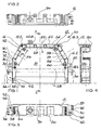
- a housing 10 is in the figures 1 to 4 with his Lower part 12 shown.
- the lower part 12 has an im present case planar surface 14, which is approximately U-shaped bordered on three sides by a side wall 16 is.
- In the side wall 16 are distributed circumferentially four Bolt holes 18.1, 18.2, 18.3 and 18.4 provided in which the cover part 20 of the housing 10, from the in Fig. 3rd an outer contour is indicated by dash-dotted lines, can be screwed.
- Lid part 20 and lower part 12th enclose one between them from three sides located interior 22nd
- a Connectors 28 are used, commonly referred to as so-called spring bar is formed.
- This spring bar is the "female" counterpart to one as so-called Male connector formed connector, then For example, firmly installed in a mating housing and with There existing printed circuits are connected can.
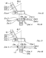
- the two Kragdian 30, 32 are, based on the Center plane 34 (Fig. 2, 3) laterally offset on the lower part 12th available.
- lower Kragwand 30 are two through holes 36, 38 available. Through this Through holes 36, 38 can be adapted in their diameter Coding pins are inserted through.
- the housing 10 can then on the wrap around collar 40 of a mating housing 42 or Not.
- the collar 40 namely the through holes 36, 38 corresponding holes 36.1 and 38.1 present, whose axes with those of the through holes 36, 38th aligned.
- Drilled holes 36.1 or 38.1 coding pins inserted are not at the same time also in the axial overlying holes 36, 38 also Plug in coding pins.
- the in the circumferential collar 40th einitzenden coding pins can thus be as well as the in the Kragwand 30 einitzenden coding pins from the outside easily recognize, so that immediately recognized immediately can be whether the "right" housing 10 to screw on the intended location of the mating housing 42 attached shall be.
- the lateral openings 24 in the present case are in the region of the bottom 14 in each case two screw holes 50, 52 adjacent.
- the screw holes 50, 52 are in after projecting inside and connected to the bottom 14 columnar wall reinforcements of the side wall 16 present.
- the two screw holes 50, 52 have such mutual distance 54 that one in the prior art known cable clamp 56 can be screwed.
- These Cable clamp 56 consists of two tabs, of which in Fig. 1, the upper flap 58 is shown.
- the two tabs the cable clamp 56 can have a cable between them pinch and then turn over their ends existing cable clamp screws 60, 62 to the Screw holes 50, 52 screwed and thereby in the Housing 10 are attached.
- the screw holes 50, 52 By the way, you can also attach earthing cables be used.
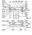
- Fig. 1 is an insert in the form of a Crimpflansches 226 (Fig. 5) used. In the following Various such inserts are shown in more detail.
- each of the insert inserts 220, 226 (Fig. 6, 5) with each laterally adjacent Side wall 16 of the lower part 12 a multi-level toothing 236 (FIGS. 5, 6 ff.).
- the multi-stage toothing 236, in the following described in more detail and in different Variations is represented represents a desirable long and thus large and one more Bending contact surface between insert and sidewall.
- the electrical resistance between the Insert and the side wall is characterized accordingly small.
- the meandering, multi-level gearing represents Good protection against penetrating splash water represents.
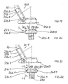
- Fig. 5 is designed as a crimp flange insert 226 shown. It has a through opening 250 with longitudinal axis 252. This longitudinal axis 252 coincides with the Longitudinal axis of an inserted into the housing 10 cable together.
- a sleeve 254 is inserted, by means of two spaced-apart circumferential Collar 256, 258 in the longitudinal direction of the longitudinal axis 252nd tension-, pressure-resistant and thus safe to move and also still secured against rotation in the insert piece 226.
- the Sleeve 254 is designed cross-sectionally matching the cable.
- the cable sheath and optionally a braided shield lie in the assembled state on the sleeve 254 close to while the wires of the cable are passed through the sleeve 254 become.
- On the cable sheath is another, not shown Slipped sleeve and crimped to the jacket. As a result, the jacket can be fixedly mounted on the sleeve 254 become.
- the insert 226 (Fig.5) has in the present case a parallelepiped-shaped body 260 with a continuous opening 250. From this body 260 collar on its two opposite Side walls 262, 264 each have two projections 266, 268 off. The two side walls 262, 264 abut in the built-in Condition on the side wall 16 of the housing 10 at.
- Each projection 266, 268 has side walls 262, 264 projecting and on the body or on its side walls 262, 264 abutting side surfaces 270, 272.
- the a side surface 270 is less than 90 degrees Angle 274 to the side wall 262, 264 aligned. Your from the side wall 262, 264 projecting length LS is so longer than the corresponding overhanging length L of the other Side surface 272, which is at a right angle 276 of the Side wall 262 and 264 protrudes.
- the cantilevered summed length of both side surfaces 270, 272 of both Projections 266 (or 268) is 2 LS + 2 L and is greater than 2 L.
- a longitudinal rib 280 is formed on each side surface 270.
- 26 rubs the longitudinal rib 280 at the abutment surface or Contact surface of the side wall. This is one dense system or a continuous contact given between insert and side wall.
- the projections 266, 268 with the longitudinal ribs 280 are formed, the insert 226 is press-fitted from "above” onto the Removed from the lid part lower part 12 can be used.
- the side wall 16 are corresponding indentations and Projections, the projections 266, 268 and their mutual Arrangement adapted accordingly. The insert 226 then sits with a press fit in the side wall 16.
- the insert 220 represents a blind plug, as already stated is.
- the insert 220 has the same projections 266, 268 and longitudinal ribs 280 as the insert 226 and sits with a corresponding press fit in the side wall 16th Its opening 282 is on one side by a front side Wall 284 closed. As a result, the insert 220 forms a closure for the relevant opening in the side wall 16.
- the inserts 220, 226 can optionally in the Openings 24, 26 of the housing 10 are used.
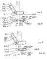
- the housing 10.3 shown in Fig. 9 corresponds to the above described housings with the difference of a different teeth 236.3 between the respective insert 220.3, 226.3 and the respective side wall 16.
- From the cuboid body 260 of the insert 226.3 (Fig. 10) projects laterally each one in cross section dovetail-shaped projection 266.3, 268.3. Its opposite side surfaces 270.3, 272.3 are obliquely to the longitudinal axis 252 available.
- Their length is LS thus larger than the projecting length L of the relevant Projection 266.3 or 268.3. It applies to everyone Projection that the two lengths LS are larger than both Lengths L.
- a toothing 236.4 present, consisting of a rectangular in plan Projection 266.2 (268.2) and a triangular projection 266.4 (268.4).
- the laterally facing ones Side surfaces 270.2 and 272 at the projection 266.2 as well as 270.2 and 270.4 at the lead 266.4 are partial right-angled (side surface 270.2, 272) respectively obliquely (side surface 270.4) at insert 226.4 or designed as blind plug 220.4 trained insert.
- the summed length of all protruding side surfaces the projections on one side of the cuboid body is 3 L + LS and is therefore greater than 2 L.
- teeth 236.5 (FIG. 13) of the housing 10.5 is between the insert 220.5 or 226.5 and the respective side wall 16 of this housing summed up Collar length as great as the teeth 236.4 according to FIGS. 11 and 12.
- the difference is merely in that between the oblique side surface 270.4 of the projection 266.4 and the adjacent, below 90 degrees to Longitudinal axis 252 aligned side surface 272 of the adjacent Projection 266.2 a longitudinally extending Side surface 273 is present.
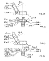
- the teeth shown in Fig. 15, 16 236.6 between an insert 220.6 or 226.6 and the relevant side wall 16 of a housing 10.6 has this above accumulated Kraginaten or sidewall lengths of 3 L + LS on.
- the gearing 236.4 (FIGS. 11, 12) is triangular in cross-section Projection 266.4 with its upper in the drawing Side surface 270.2 flush with the outer surface of the cuboid Body 260, while in the gearing 236.4 (FIG. 11, FIG. 12) is not the case.
- the local projection has 266.4 a recess 290 to the corresponding outer wall of the cuboidal body 260.
- the teeth 236.7 in the housing 10.7 or the inserts 220.7 and 226.7 which can be inserted into these housings each have two projections 266.2, 268.2, as is also the case with the toothing 236.2 (FIGS. 7, 8) are.
- the upper in the drawing projection 266.2 respectively 268.2 of the teeth 236.7 is flush with the outer wall the cuboid body 260, as is similar also with the toothing 236.6 (FIGS. 15, 16).
- a recess formed by a side wall 262 the projection 266.2 and the outer wall of the cuboid Body 260 available.
- 4 L 4 LS.
- the teeth 236.8 shown in FIGS. 19 and 20 of the Housing 10.8 has a hammerhead training on the relevant insert 220.8 or 226.8.
- the Projection 266.8, 268.8 on each of the opposite Side of the cuboid body 260 has a in the Drawing upper and lower single-stage side surface training, respectively so that each projection 266.8, 268.8 a two-stage Has teeth. Every gearing becomes one stepped side surface 273 formed by the Angled protruding length is composed of L / 2 + T + L / 2. Both step-shaped side walls 273 have this adds up to a total length of 2 L + 2 T. This measure is greater than 2 L.
- the teeth shown in Fig. 21, 22 236.9 of the housing 10.9 is formed like a truncated pyramid.
- One and only Projection 266.9, 268.9 of the insert 226.9 has opposite, obliquely aligned to the longitudinal axis 252 Side surfaces 270.9 with a respective length LS.
- the summed up Lengths of the projecting side surfaces of a projection have the length 2 LS. This measure is greater than the value 2 L.
- the inserts 220.9 the in the side walls 16 as dummy plugs, the corresponding applies. Incidentally, this applies comparatively to all projecting inserts 220.
- the illustrated gears apply in the same way for corresponding Plugs.
- each a cantilevered Cross rib 298 available on the right-angled to the toothed walls of the cuboid Body 260 existing two other outsides the inserts 226, 220 is each a cantilevered Cross rib 298 available.
- the transverse rib 298 is present Case not only on the outside visible in the figures 296, but also on the opposite Outside of the cuboid body 260 available.
- These Transverse ribs abut on the one hand on the bottom 14 of the lower part 12 and on the other hand from the inside to that in the drawing is not shown cover part, the top of the lower part 12 and thus also on the inserts 220 and 226 is tight.
- the inserts 220, 226 and the above, by the respective Gearing differing inserts have characterized not just an intimate touch through her through the respective teeth and the longitudinal ribs 280 caused Press fit with the walls 16, but also a splash-proof Attachment to the rest of the inserts adjacent Walls, namely the bottom 14 and the lid part.
- the housing 10 is thus circumferentially close to the outer surfaces of the insert 220 and 226, respectively.
Landscapes
- Details Of Connecting Devices For Male And Female Coupling (AREA)
- Connector Housings Or Holding Contact Members (AREA)
- Drilling And Boring (AREA)
- Coupling Device And Connection With Printed Circuit (AREA)
Claims (13)
- Boítier (10) qui est configuré de sorte à pouvoir être vissé sur un boítier antagoniste (42), moyennant quoi un connecteur (28) peut être inséré dans le boítier (10).caractérisé en ce queavec un boítier (10) en métal plein,avec au moins une ouverture obturable (24, 26) dans le boítier (10), par laquelle on peut passer à l'état ouvert un câble à relier avec le connecteur (28),avec un dispositif pour visser le boítier (10) au porte-à-faux (40) du boítier antagoniste (42), moyennant quoi ce dispositif existe, dépassant de la paroi latérale (16) formée entre le fond (14) de la partie inférieure (12) et la partie couvercle (20) du boítier, etavec un dispositif de codage (30, 36, 38),le dispositif de codage (30, 36, 38) possède une première partie en porte-à-faux (30) dépassant d'au moins une des deux zones de paroi latérale (16.1, 16.2) se faisant face de la paroi latérale (16),dans cette première partie en porte-à-faux (30), il y a au moins un trou traversant (36, 38) pour une pièce de codage,la pièce de codage est configurée comme une goupille pouvant être enfilée dans le trou traversant (36, 38) et pouvant s'introduire en même temps dans un trou (36.1, 38.1) coaxial avec ce trou traversant (36, 38) dans le porte-à-faux (40) du boítier antagoniste (42),une deuxième partie en porte-à-faux (32) est présente sur chacune des deux zones (16.1, 16.2) se faisant face de la paroi latérale (16), qui est dotée d'un trou traversant (46) pour visser le boítier (10) sur le porte-à-faux (40) du boítier antagoniste (42), moyennant quoile trou traversant (36, 38) de la première partie en porte-à-faux (30) n'est pas coaxial avec le trou traversant (46) de la deuxième partie en porte-à-faux (32).
- Boítier selon la revendication 1,
caractérisé en ce quela première partie en porte-à-faux (30), dépassant de la zone de paroi latérale (16.1, 16.2), est décentrée par rapport au plan médian (34) du boítier (10). - Boítier selon la revendication 2,
caractérisé en ce queles première et deuxième parties en porte-à-faux (30, 32) sont disposées décentrées par rapport au plan médian (34) du boítier (10),la première partie en porte-à-faux (30), décalée latéralement et en hauteur par rapport à la deuxième partie en porte-à-faux (32), est présente sur une zone de la paroi latérale (16.1, 16.2) respectivement. - Boítier selon l'une quelconque revendications précédentes,
caractérisé en ce queil y a un insert (220, 226) insérable dans les ouvertures obturables (24, 26),qui est configuré comme un bouchon métallique (220) obturant l'ouverture (24, 26) oucomme une fixation métallique de câble (226) maintenant le câble sur le boítier (10) et insérable dans l'ouverture (24, 26),moyennant quoi l'insert (220, 226) respectif comporte des saillies (266, 268) qui correspondent avec des creux dans le boítier (10), de telle sorte que l'insert (220, 226) peut être glissé dans le boítier (10) le long de ces saillies (266, 268), qui représentent des guides longitudinaux pour cet insert. - Boítier selon l'une quelconque revendications précédentes,
caractérisé en ce queil y a deux trous de vis (50, 52), dans lesquels un collier de câble (56) peut être fixé par vissage (60, 62) à l'intérieur du boítier avec ses deux extrémités de collier. - Boítier selon la revendication 5,
caractérisé en ce queil y a un trou de vis (50, 52) pour la fixation d'un conducteur de terre. - Boítier selon l'une quelconque revendications précédentes,
caractérisé en ce queil y a une denture multi-étagée (236) entre l'insert (220, 226) et le boítier (10), de telle sorte queles surfaces latérales (270, 272), existant transversalement par rapport à l'axe longitudinal de l'ouverture du boítier, de la au moins une saillie (266, 268), possèdent respectivement une longueur dépassante qui, additionnée, est plus de deux fois plus grande que la longueur L de cette saillie dépassant perpendiculairement à l'axe longitudinal de l'ouverture du boítier. - Boítier selon la revendication 7,
caractérisé en ce queil y a au moins une nervure longitudinale (280) et / ou un bombement dépassant sur les surfaces latérales (270, 272, 273) d'une saillie (266, 268). - Boítier selon la revendication 7 ou 8,
caractérisé en ce queil y a au moins deux saillies (266, 268) sur une paroi latérale (262) de l'insert (220, 226). - Boítier selon la revendication 9,
caractérisé en ce queune surface latérale (270) de l'une des plusieurs saillies (266, 268) ne s'étend pas parallèlement à la surface latérale opposée (272) de cette saillie. - Boítier selon l'une quelconque revendications 7 à 10,
caractérisé en ce queune saillie (266.3, 268.3) est configurée de section en queue d'aronde ou trapézoïdale. - Boítier selon la revendication 7,
caractérisé en ce queil y a une nervure transversale (298) sur au moins une des surfaces extérieures (296) de l'insert (220, 226) ne comportant pas de saillies. - Boítier selon la revendication 12,
caractérisé en ce quela nervure transversale (298) s'étend sur l'ensemble de la face extérieure (296) du corps (260).
Applications Claiming Priority (2)
| Application Number | Priority Date | Filing Date | Title |
|---|---|---|---|
| DE29908277U | 1999-05-08 | ||
| DE29908277U DE29908277U1 (de) | 1999-05-08 | 1999-05-08 | Gehäuse für Steckverbinder |
Publications (2)
| Publication Number | Publication Date |
|---|---|
| EP1052737A1 EP1052737A1 (fr) | 2000-11-15 |
| EP1052737B1 true EP1052737B1 (fr) | 2003-10-01 |
Family
ID=8073355
Family Applications (1)
| Application Number | Title | Priority Date | Filing Date |
|---|---|---|---|
| EP00109608A Expired - Lifetime EP1052737B1 (fr) | 1999-05-08 | 2000-05-05 | Boítier de connecteur à fiche |
Country Status (3)
| Country | Link |
|---|---|
| EP (1) | EP1052737B1 (fr) |
| AT (1) | ATE251350T1 (fr) |
| DE (2) | DE29908277U1 (fr) |
Cited By (1)
| Publication number | Priority date | Publication date | Assignee | Title |
|---|---|---|---|---|
| EP1995829A1 (fr) | 2007-05-25 | 2008-11-26 | Fred R. Schmitt | Système de codage pour connecteurs à fiches subminiatures D |
Families Citing this family (4)
| Publication number | Priority date | Publication date | Assignee | Title |
|---|---|---|---|---|
| EP1357643B1 (fr) * | 2002-04-22 | 2010-07-21 | Fred R. Schmitt | Bus-boîtier et piéces d'insertion pour les ouvertures de cable du Bus-boîtier |
| DE202004014562U1 (de) * | 2004-09-16 | 2004-11-18 | Schmitt, Fred R. | Gehäuse für Steckverbinder |
| WO2009043862A1 (fr) * | 2007-10-04 | 2009-04-09 | Nordia Innovation Ab | Couvercle de connecteur |
| DE202015000163U1 (de) | 2015-01-15 | 2015-04-01 | Martin Danielczick | Vorrichtung zur Befestigung eines Steckverbindergehäuses an einer Frontplatte |
Family Cites Families (4)
| Publication number | Priority date | Publication date | Assignee | Title |
|---|---|---|---|---|
| US4842543A (en) * | 1988-06-03 | 1989-06-27 | Amp Incorporated | Contact protection system for electrical connectors |
| US5011436A (en) * | 1988-11-04 | 1991-04-30 | Amp Incorporated | Hermaphroditic keys |
| US4929184A (en) * | 1989-06-07 | 1990-05-29 | Amp Incorporated | Keyed electrical connectors with jackscrews |
| DE29801984U1 (de) * | 1998-02-06 | 1998-03-26 | Schmitt, Fred R., 74388 Talheim | Steckverbinder-Gehäuse im 19 Zoll-Gerätesystem |
-
1999
- 1999-05-08 DE DE29908277U patent/DE29908277U1/de not_active Expired - Lifetime
-
2000
- 2000-05-05 EP EP00109608A patent/EP1052737B1/fr not_active Expired - Lifetime
- 2000-05-05 DE DE50003877T patent/DE50003877D1/de not_active Expired - Lifetime
- 2000-05-05 AT AT00109608T patent/ATE251350T1/de active
Cited By (1)
| Publication number | Priority date | Publication date | Assignee | Title |
|---|---|---|---|---|
| EP1995829A1 (fr) | 2007-05-25 | 2008-11-26 | Fred R. Schmitt | Système de codage pour connecteurs à fiches subminiatures D |
Also Published As
| Publication number | Publication date |
|---|---|
| EP1052737A1 (fr) | 2000-11-15 |
| DE29908277U1 (de) | 1999-07-22 |
| DE50003877D1 (de) | 2003-11-06 |
| ATE251350T1 (de) | 2003-10-15 |
Similar Documents
| Publication | Publication Date | Title |
|---|---|---|
| DE102006016882B4 (de) | Steckverbinder | |
| DE102011115637B4 (de) | Elektrische Anschlussklemme | |
| AT503089B1 (de) | Aufsatzteil | |
| DE112009000065B4 (de) | Kabelbaum | |
| DE19951455C1 (de) | Kabelanschluss- oder -verbindungseinrichtung | |
| DE19625601B4 (de) | Steckerverbinderanordnung mit Mechanismus zur Bestätigung des Sitzes der Steckverbindergehäuse und Verfahren zur Befestigung der Steckverbindergehäuse | |
| DE4222452A1 (de) | Abgeschirmter verbinder | |
| DE69904095T2 (de) | Elektrischer Steckverbinder zur Herstellung des Kontakts mit mindestens einer flachen Leiterfolie | |
| DE102007045400B4 (de) | Netzstecker | |
| EP1052737B1 (fr) | Boítier de connecteur à fiche | |
| EP0935314B9 (fr) | Boîtier de connecteur pour systèmes d'appareils à 19 pouce | |
| EP0838879A1 (fr) | Boítier de connecteur à fiche blindé contre les intérférences électromagnétiques | |
| DE102020109823A1 (de) | Entladestecker für einen Akku eines Elektrofahrrades | |
| DE29907005U1 (de) | Anschluß- und/oder Verbindungsklemme für ein elektrisches Gerät | |
| DE20206394U1 (de) | Bus-Gehäuse und Einsatzstücke für die Kabeleinlassöffnungen des Bus-Gehäuses | |
| DE102020003770B4 (de) | Elektrischer Kontakt | |
| EP1357643B1 (fr) | Bus-boîtier et piéces d'insertion pour les ouvertures de cable du Bus-boîtier | |
| EP0915535B1 (fr) | Boítier de connecteur blindé contre les interférences électromagnétiques et éléments de fermeture des arrivées de câble | |
| DE29801984U1 (de) | Steckverbinder-Gehäuse im 19 Zoll-Gerätesystem | |
| DE69301409T2 (de) | Element eines elektrischen Verbinders | |
| DE19647233C2 (de) | Stecker für elektrische Kabel | |
| WO2024125704A1 (fr) | Insert de connecteur à fiche pour un connecteur électrique à fiche | |
| DE20205811U1 (de) | Steckverbinder | |
| DE29817007U1 (de) | Führungsstift für elektrische Steckverbindungen | |
| DE10151455A1 (de) | Schwachstromanschluss vom Typ Modulsteckbuchse mit Abschirmungskappe |
Legal Events
| Date | Code | Title | Description |
|---|---|---|---|
| PUAI | Public reference made under article 153(3) epc to a published international application that has entered the european phase |
Free format text: ORIGINAL CODE: 0009012 |
|
| AK | Designated contracting states |
Kind code of ref document: A1 Designated state(s): AT BE CH CY DE DK ES FI FR GB GR IE IT LI LU MC NL PT SE |
|
| AX | Request for extension of the european patent |
Free format text: AL;LT;LV;MK;RO;SI |
|
| 17P | Request for examination filed |
Effective date: 20010317 |
|
| 17Q | First examination report despatched |
Effective date: 20010515 |
|
| AKX | Designation fees paid |
Free format text: AT BE CH CY DE DK ES FI FR GB GR IE IT LI LU MC NL PT SE |
|
| GRAH | Despatch of communication of intention to grant a patent |
Free format text: ORIGINAL CODE: EPIDOS IGRA |
|
| GRAS | Grant fee paid |
Free format text: ORIGINAL CODE: EPIDOSNIGR3 |
|
| GRAA | (expected) grant |
Free format text: ORIGINAL CODE: 0009210 |
|
| AK | Designated contracting states |
Kind code of ref document: B1 Designated state(s): AT BE CH CY DE DK ES FI FR GB GR IE IT LI LU MC NL PT SE |
|
| PG25 | Lapsed in a contracting state [announced via postgrant information from national office to epo] |
Ref country code: IT Free format text: LAPSE BECAUSE OF FAILURE TO SUBMIT A TRANSLATION OF THE DESCRIPTION OR TO PAY THE FEE WITHIN THE PRE;WARNING: LAPSES OF ITALIAN PATENTS WITH EFFECTIVE DATE BEFORE 2007 MAY HAVE OCCURRED AT ANY TIME BEFORE 2007. THE CORRECT EFFECTIVE DATE MAY BE DIFFERENT FROM THE ONE RECORDED.SCRIBED TIME-LIMIT Effective date: 20031001 Ref country code: CY Free format text: LAPSE BECAUSE OF FAILURE TO SUBMIT A TRANSLATION OF THE DESCRIPTION OR TO PAY THE FEE WITHIN THE PRESCRIBED TIME-LIMIT Effective date: 20031001 Ref country code: FI Free format text: LAPSE BECAUSE OF FAILURE TO SUBMIT A TRANSLATION OF THE DESCRIPTION OR TO PAY THE FEE WITHIN THE PRESCRIBED TIME-LIMIT Effective date: 20031001 Ref country code: IE Free format text: LAPSE BECAUSE OF FAILURE TO SUBMIT A TRANSLATION OF THE DESCRIPTION OR TO PAY THE FEE WITHIN THE PRESCRIBED TIME-LIMIT Effective date: 20031001 |
|
| REG | Reference to a national code |
Ref country code: GB Ref legal event code: FG4D Free format text: NOT ENGLISH |
|
| REG | Reference to a national code |
Ref country code: CH Ref legal event code: EP |
|
| REG | Reference to a national code |
Ref country code: IE Ref legal event code: FG4D Free format text: GERMAN |
|
| REF | Corresponds to: |
Ref document number: 50003877 Country of ref document: DE Date of ref document: 20031106 Kind code of ref document: P |
|
| REG | Reference to a national code |
Ref country code: CH Ref legal event code: NV Representative=s name: ING. MARCO ZARDI C/O M. ZARDI & CO. S.A. |
|
| PG25 | Lapsed in a contracting state [announced via postgrant information from national office to epo] |
Ref country code: DK Free format text: LAPSE BECAUSE OF FAILURE TO SUBMIT A TRANSLATION OF THE DESCRIPTION OR TO PAY THE FEE WITHIN THE PRESCRIBED TIME-LIMIT Effective date: 20040101 Ref country code: GR Free format text: LAPSE BECAUSE OF FAILURE TO SUBMIT A TRANSLATION OF THE DESCRIPTION OR TO PAY THE FEE WITHIN THE PRESCRIBED TIME-LIMIT Effective date: 20040101 |
|
| PG25 | Lapsed in a contracting state [announced via postgrant information from national office to epo] |
Ref country code: ES Free format text: LAPSE BECAUSE OF FAILURE TO SUBMIT A TRANSLATION OF THE DESCRIPTION OR TO PAY THE FEE WITHIN THE PRESCRIBED TIME-LIMIT Effective date: 20040112 |
|
| REG | Reference to a national code |
Ref country code: SE Ref legal event code: TRGR |
|
| GBT | Gb: translation of ep patent filed (gb section 77(6)(a)/1977) |
Effective date: 20040118 |
|
| PG25 | Lapsed in a contracting state [announced via postgrant information from national office to epo] |
Ref country code: LU Free format text: LAPSE BECAUSE OF NON-PAYMENT OF DUE FEES Effective date: 20040505 |
|
| PG25 | Lapsed in a contracting state [announced via postgrant information from national office to epo] |
Ref country code: BE Free format text: LAPSE BECAUSE OF NON-PAYMENT OF DUE FEES Effective date: 20040531 Ref country code: MC Free format text: LAPSE BECAUSE OF NON-PAYMENT OF DUE FEES Effective date: 20040531 |
|
| REG | Reference to a national code |
Ref country code: IE Ref legal event code: FD4D |
|
| ET | Fr: translation filed | ||
| PLBE | No opposition filed within time limit |
Free format text: ORIGINAL CODE: 0009261 |
|
| STAA | Information on the status of an ep patent application or granted ep patent |
Free format text: STATUS: NO OPPOSITION FILED WITHIN TIME LIMIT |
|
| 26N | No opposition filed |
Effective date: 20040702 |
|
| BERE | Be: lapsed |
Owner name: *SCHMITT FRED Effective date: 20040531 |
|
| REG | Reference to a national code |
Ref country code: CH Ref legal event code: PCAR Free format text: ISLER & PEDRAZZINI AG;POSTFACH 1772;8027 ZUERICH (CH) |
|
| PG25 | Lapsed in a contracting state [announced via postgrant information from national office to epo] |
Ref country code: PT Free format text: LAPSE BECAUSE OF NON-PAYMENT OF DUE FEES Effective date: 20040301 |
|
| REG | Reference to a national code |
Ref country code: FR Ref legal event code: PLFP Year of fee payment: 17 |
|
| REG | Reference to a national code |
Ref country code: FR Ref legal event code: PLFP Year of fee payment: 18 |
|
| REG | Reference to a national code |
Ref country code: DE Ref legal event code: R082 Ref document number: 50003877 Country of ref document: DE Representative=s name: PATENTANWAELTE DR.-ING. GERHARD CLEMENS, DR. R, DE Ref country code: DE Ref legal event code: R081 Ref document number: 50003877 Country of ref document: DE Owner name: INOTEC ELECTRONICS GMBH, DE Free format text: FORMER OWNER: SCHMITT, FRED R., 74388 TALHEIM, DE |
|
| REG | Reference to a national code |
Ref country code: CH Ref legal event code: PUE Owner name: INOTEC ELECTRONICS GMBH, DE Free format text: FORMER OWNER: SCHMITT, FRED, DE |
|
| REG | Reference to a national code |
Ref country code: GB Ref legal event code: 732E Free format text: REGISTERED BETWEEN 20180412 AND 20180418 |
|
| REG | Reference to a national code |
Ref country code: FR Ref legal event code: PLFP Year of fee payment: 19 |
|
| PGFP | Annual fee paid to national office [announced via postgrant information from national office to epo] |
Ref country code: NL Payment date: 20190521 Year of fee payment: 20 |
|
| PGFP | Annual fee paid to national office [announced via postgrant information from national office to epo] |
Ref country code: DE Payment date: 20190514 Year of fee payment: 20 |
|
| PGFP | Annual fee paid to national office [announced via postgrant information from national office to epo] |
Ref country code: FR Payment date: 20190521 Year of fee payment: 20 Ref country code: SE Payment date: 20190523 Year of fee payment: 20 |
|
| PGFP | Annual fee paid to national office [announced via postgrant information from national office to epo] |
Ref country code: CH Payment date: 20190523 Year of fee payment: 20 |
|
| PGFP | Annual fee paid to national office [announced via postgrant information from national office to epo] |
Ref country code: GB Payment date: 20190523 Year of fee payment: 20 Ref country code: AT Payment date: 20190517 Year of fee payment: 20 |
|
| REG | Reference to a national code |
Ref country code: DE Ref legal event code: R071 Ref document number: 50003877 Country of ref document: DE |
|
| REG | Reference to a national code |
Ref country code: NL Ref legal event code: MK Effective date: 20200504 |
|
| REG | Reference to a national code |
Ref country code: CH Ref legal event code: PL |
|
| REG | Reference to a national code |
Ref country code: GB Ref legal event code: PE20 Expiry date: 20200504 |
|
| REG | Reference to a national code |
Ref country code: SE Ref legal event code: EUG |
|
| REG | Reference to a national code |
Ref country code: AT Ref legal event code: MK07 Ref document number: 251350 Country of ref document: AT Kind code of ref document: T Effective date: 20200505 |
|
| PG25 | Lapsed in a contracting state [announced via postgrant information from national office to epo] |
Ref country code: GB Free format text: LAPSE BECAUSE OF EXPIRATION OF PROTECTION Effective date: 20200504 |