EP1052737B1 - Plug connector housing - Google Patents
Plug connector housing Download PDFInfo
- Publication number
- EP1052737B1 EP1052737B1 EP00109608A EP00109608A EP1052737B1 EP 1052737 B1 EP1052737 B1 EP 1052737B1 EP 00109608 A EP00109608 A EP 00109608A EP 00109608 A EP00109608 A EP 00109608A EP 1052737 B1 EP1052737 B1 EP 1052737B1
- Authority
- EP
- European Patent Office
- Prior art keywords
- housing
- insert
- bore
- housing according
- projecting part
- Prior art date
- Legal status (The legal status is an assumption and is not a legal conclusion. Google has not performed a legal analysis and makes no representation as to the accuracy of the status listed.)
- Expired - Lifetime
Links
Images
Classifications
-
- H—ELECTRICITY
- H01—ELECTRIC ELEMENTS
- H01R—ELECTRICALLY-CONDUCTIVE CONNECTIONS; STRUCTURAL ASSOCIATIONS OF A PLURALITY OF MUTUALLY-INSULATED ELECTRICAL CONNECTING ELEMENTS; COUPLING DEVICES; CURRENT COLLECTORS
- H01R13/00—Details of coupling devices of the kinds covered by groups H01R12/70 or H01R24/00 - H01R33/00
- H01R13/64—Means for preventing incorrect coupling
-
- H—ELECTRICITY
- H01—ELECTRIC ELEMENTS
- H01R—ELECTRICALLY-CONDUCTIVE CONNECTIONS; STRUCTURAL ASSOCIATIONS OF A PLURALITY OF MUTUALLY-INSULATED ELECTRICAL CONNECTING ELEMENTS; COUPLING DEVICES; CURRENT COLLECTORS
- H01R13/00—Details of coupling devices of the kinds covered by groups H01R12/70 or H01R24/00 - H01R33/00
- H01R13/648—Protective earth or shield arrangements on coupling devices, e.g. anti-static shielding
- H01R13/658—High frequency shielding arrangements, e.g. against EMI [Electro-Magnetic Interference] or EMP [Electro-Magnetic Pulse]
- H01R13/6581—Shield structure
-
- H—ELECTRICITY
- H01—ELECTRIC ELEMENTS
- H01R—ELECTRICALLY-CONDUCTIVE CONNECTIONS; STRUCTURAL ASSOCIATIONS OF A PLURALITY OF MUTUALLY-INSULATED ELECTRICAL CONNECTING ELEMENTS; COUPLING DEVICES; CURRENT COLLECTORS
- H01R13/00—Details of coupling devices of the kinds covered by groups H01R12/70 or H01R24/00 - H01R33/00
- H01R13/46—Bases; Cases
- H01R13/516—Means for holding or embracing insulating body, e.g. casing, hoods
Definitions
- the invention relates to a housing for DIN 41 612th standardized plug-in connector for screw-on connection corresponding mating connector.
- a connector housing of initially known type in accordance with DIN 41 612th standardized connectors can be used.
- the corresponding mating connectors are in electronic inserts according to the 19 inch system available. These bays are in rack can be used according to this 19 inch system.
- the Connector housing is a zinc die-cast part and consists of electrically conductive solid material.
- the by the metallic housing possible increase of Störstrahlplo is in the field of housing openings, through which an electrical cable enters the interior of the Housing introduced and with the existing there Connector can be connected, thereby ensuring that in the relevant cable opening one the same Closing blind plug or a cable in the Housing opening holding cable attachment are used can.
- These respective inserts also exist made of metallic material.
- the invention is based on the object, a housing of the above to specify that with a slightly from the outside recognizing coding device is equipped and the be produced economically economically can.
- the housing according to the invention can be a large interference beam safety Offer. This is achieved once by the fact that Housing made of metallic material. The height Störstrahlterrorism can also in the range of cable entry openings be achieved. The openings on the one hand and the the cable to the housing holding insert on the other have such mutual projections and recesses that the insert in the housing opening a safe has electrical contact with the housing. This will be the electrical resistance between insert and housing desirable small and thus a good RF transition between insert and housing possible.
- the coding device includes separate Kragwel to the opposite side wall portions of the Housing, on the one hand part of the encoder and on the other hand are part of the Anschraubbefest Trent to the To attach housing to a counter housing screwed.
- Examples of externally arranged on the housing coding are the subject of subclaims 2 and 3 and are shown in an embodiment in the drawing.
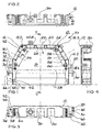
- a housing 10 is in the figures 1 to 4 with his Lower part 12 shown.
- the lower part 12 has an im present case planar surface 14, which is approximately U-shaped bordered on three sides by a side wall 16 is.
- In the side wall 16 are distributed circumferentially four Bolt holes 18.1, 18.2, 18.3 and 18.4 provided in which the cover part 20 of the housing 10, from the in Fig. 3rd an outer contour is indicated by dash-dotted lines, can be screwed.
- Lid part 20 and lower part 12th enclose one between them from three sides located interior 22nd
- a Connectors 28 are used, commonly referred to as so-called spring bar is formed.
- This spring bar is the "female" counterpart to one as so-called Male connector formed connector, then For example, firmly installed in a mating housing and with There existing printed circuits are connected can.
- the two Kragdian 30, 32 are, based on the Center plane 34 (Fig. 2, 3) laterally offset on the lower part 12th available.
- lower Kragwand 30 are two through holes 36, 38 available. Through this Through holes 36, 38 can be adapted in their diameter Coding pins are inserted through.
- the housing 10 can then on the wrap around collar 40 of a mating housing 42 or Not.
- the collar 40 namely the through holes 36, 38 corresponding holes 36.1 and 38.1 present, whose axes with those of the through holes 36, 38th aligned.
- Drilled holes 36.1 or 38.1 coding pins inserted are not at the same time also in the axial overlying holes 36, 38 also Plug in coding pins.
- the in the circumferential collar 40th einitzenden coding pins can thus be as well as the in the Kragwand 30 einitzenden coding pins from the outside easily recognize, so that immediately recognized immediately can be whether the "right" housing 10 to screw on the intended location of the mating housing 42 attached shall be.
- the lateral openings 24 in the present case are in the region of the bottom 14 in each case two screw holes 50, 52 adjacent.
- the screw holes 50, 52 are in after projecting inside and connected to the bottom 14 columnar wall reinforcements of the side wall 16 present.
- the two screw holes 50, 52 have such mutual distance 54 that one in the prior art known cable clamp 56 can be screwed.
- These Cable clamp 56 consists of two tabs, of which in Fig. 1, the upper flap 58 is shown.
- the two tabs the cable clamp 56 can have a cable between them pinch and then turn over their ends existing cable clamp screws 60, 62 to the Screw holes 50, 52 screwed and thereby in the Housing 10 are attached.
- the screw holes 50, 52 By the way, you can also attach earthing cables be used.
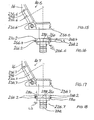
- Fig. 1 is an insert in the form of a Crimpflansches 226 (Fig. 5) used. In the following Various such inserts are shown in more detail.
- each of the insert inserts 220, 226 (Fig. 6, 5) with each laterally adjacent Side wall 16 of the lower part 12 a multi-level toothing 236 (FIGS. 5, 6 ff.).
- the multi-stage toothing 236, in the following described in more detail and in different Variations is represented represents a desirable long and thus large and one more Bending contact surface between insert and sidewall.
- the electrical resistance between the Insert and the side wall is characterized accordingly small.
- the meandering, multi-level gearing represents Good protection against penetrating splash water represents.
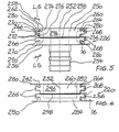
- Fig. 5 is designed as a crimp flange insert 226 shown. It has a through opening 250 with longitudinal axis 252. This longitudinal axis 252 coincides with the Longitudinal axis of an inserted into the housing 10 cable together.
- a sleeve 254 is inserted, by means of two spaced-apart circumferential Collar 256, 258 in the longitudinal direction of the longitudinal axis 252nd tension-, pressure-resistant and thus safe to move and also still secured against rotation in the insert piece 226.
- the Sleeve 254 is designed cross-sectionally matching the cable.
- the cable sheath and optionally a braided shield lie in the assembled state on the sleeve 254 close to while the wires of the cable are passed through the sleeve 254 become.
- On the cable sheath is another, not shown Slipped sleeve and crimped to the jacket. As a result, the jacket can be fixedly mounted on the sleeve 254 become.
- the insert 226 (Fig.5) has in the present case a parallelepiped-shaped body 260 with a continuous opening 250. From this body 260 collar on its two opposite Side walls 262, 264 each have two projections 266, 268 off. The two side walls 262, 264 abut in the built-in Condition on the side wall 16 of the housing 10 at.
- Each projection 266, 268 has side walls 262, 264 projecting and on the body or on its side walls 262, 264 abutting side surfaces 270, 272.
- the a side surface 270 is less than 90 degrees Angle 274 to the side wall 262, 264 aligned. Your from the side wall 262, 264 projecting length LS is so longer than the corresponding overhanging length L of the other Side surface 272, which is at a right angle 276 of the Side wall 262 and 264 protrudes.
- the cantilevered summed length of both side surfaces 270, 272 of both Projections 266 (or 268) is 2 LS + 2 L and is greater than 2 L.
- a longitudinal rib 280 is formed on each side surface 270.
- 26 rubs the longitudinal rib 280 at the abutment surface or Contact surface of the side wall. This is one dense system or a continuous contact given between insert and side wall.
- the projections 266, 268 with the longitudinal ribs 280 are formed, the insert 226 is press-fitted from "above” onto the Removed from the lid part lower part 12 can be used.
- the side wall 16 are corresponding indentations and Projections, the projections 266, 268 and their mutual Arrangement adapted accordingly. The insert 226 then sits with a press fit in the side wall 16.
- the insert 220 represents a blind plug, as already stated is.
- the insert 220 has the same projections 266, 268 and longitudinal ribs 280 as the insert 226 and sits with a corresponding press fit in the side wall 16th Its opening 282 is on one side by a front side Wall 284 closed. As a result, the insert 220 forms a closure for the relevant opening in the side wall 16.
- the inserts 220, 226 can optionally in the Openings 24, 26 of the housing 10 are used.
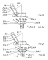
- the housing 10.3 shown in Fig. 9 corresponds to the above described housings with the difference of a different teeth 236.3 between the respective insert 220.3, 226.3 and the respective side wall 16.
- From the cuboid body 260 of the insert 226.3 (Fig. 10) projects laterally each one in cross section dovetail-shaped projection 266.3, 268.3. Its opposite side surfaces 270.3, 272.3 are obliquely to the longitudinal axis 252 available.
- Their length is LS thus larger than the projecting length L of the relevant Projection 266.3 or 268.3. It applies to everyone Projection that the two lengths LS are larger than both Lengths L.
- a toothing 236.4 present, consisting of a rectangular in plan Projection 266.2 (268.2) and a triangular projection 266.4 (268.4).
- the laterally facing ones Side surfaces 270.2 and 272 at the projection 266.2 as well as 270.2 and 270.4 at the lead 266.4 are partial right-angled (side surface 270.2, 272) respectively obliquely (side surface 270.4) at insert 226.4 or designed as blind plug 220.4 trained insert.
- the summed length of all protruding side surfaces the projections on one side of the cuboid body is 3 L + LS and is therefore greater than 2 L.
- teeth 236.5 (FIG. 13) of the housing 10.5 is between the insert 220.5 or 226.5 and the respective side wall 16 of this housing summed up Collar length as great as the teeth 236.4 according to FIGS. 11 and 12.
- the difference is merely in that between the oblique side surface 270.4 of the projection 266.4 and the adjacent, below 90 degrees to Longitudinal axis 252 aligned side surface 272 of the adjacent Projection 266.2 a longitudinally extending Side surface 273 is present.
- the teeth shown in Fig. 15, 16 236.6 between an insert 220.6 or 226.6 and the relevant side wall 16 of a housing 10.6 has this above accumulated Kraginaten or sidewall lengths of 3 L + LS on.
- the gearing 236.4 (FIGS. 11, 12) is triangular in cross-section Projection 266.4 with its upper in the drawing Side surface 270.2 flush with the outer surface of the cuboid Body 260, while in the gearing 236.4 (FIG. 11, FIG. 12) is not the case.
- the local projection has 266.4 a recess 290 to the corresponding outer wall of the cuboidal body 260.
- the teeth 236.7 in the housing 10.7 or the inserts 220.7 and 226.7 which can be inserted into these housings each have two projections 266.2, 268.2, as is also the case with the toothing 236.2 (FIGS. 7, 8) are.
- the upper in the drawing projection 266.2 respectively 268.2 of the teeth 236.7 is flush with the outer wall the cuboid body 260, as is similar also with the toothing 236.6 (FIGS. 15, 16).
- a recess formed by a side wall 262 the projection 266.2 and the outer wall of the cuboid Body 260 available.
- 4 L 4 LS.
- the teeth 236.8 shown in FIGS. 19 and 20 of the Housing 10.8 has a hammerhead training on the relevant insert 220.8 or 226.8.
- the Projection 266.8, 268.8 on each of the opposite Side of the cuboid body 260 has a in the Drawing upper and lower single-stage side surface training, respectively so that each projection 266.8, 268.8 a two-stage Has teeth. Every gearing becomes one stepped side surface 273 formed by the Angled protruding length is composed of L / 2 + T + L / 2. Both step-shaped side walls 273 have this adds up to a total length of 2 L + 2 T. This measure is greater than 2 L.
- the teeth shown in Fig. 21, 22 236.9 of the housing 10.9 is formed like a truncated pyramid.
- One and only Projection 266.9, 268.9 of the insert 226.9 has opposite, obliquely aligned to the longitudinal axis 252 Side surfaces 270.9 with a respective length LS.
- the summed up Lengths of the projecting side surfaces of a projection have the length 2 LS. This measure is greater than the value 2 L.
- the inserts 220.9 the in the side walls 16 as dummy plugs, the corresponding applies. Incidentally, this applies comparatively to all projecting inserts 220.
- the illustrated gears apply in the same way for corresponding Plugs.
- each a cantilevered Cross rib 298 available on the right-angled to the toothed walls of the cuboid Body 260 existing two other outsides the inserts 226, 220 is each a cantilevered Cross rib 298 available.
- the transverse rib 298 is present Case not only on the outside visible in the figures 296, but also on the opposite Outside of the cuboid body 260 available.
- These Transverse ribs abut on the one hand on the bottom 14 of the lower part 12 and on the other hand from the inside to that in the drawing is not shown cover part, the top of the lower part 12 and thus also on the inserts 220 and 226 is tight.
- the inserts 220, 226 and the above, by the respective Gearing differing inserts have characterized not just an intimate touch through her through the respective teeth and the longitudinal ribs 280 caused Press fit with the walls 16, but also a splash-proof Attachment to the rest of the inserts adjacent Walls, namely the bottom 14 and the lid part.
- the housing 10 is thus circumferentially close to the outer surfaces of the insert 220 and 226, respectively.
Abstract
Description
Die Erfindung betrifft ein Gehäuse für nach DIN 41 612 genormte Steckverbinder zum anschraubbaren Anschluß an entsprechend passende Gegen-Steckverbinder.The invention relates to a housing for DIN 41 612th standardized plug-in connector for screw-on connection corresponding mating connector.
Aus der DE-A-298 19 972 ist ein Steckverbinder-Gehäuse der eingangs genannten Art bekannt, in das nach DIN 41 612 genormte Steckverbinder eingesetzt werden können. Die entsprechend passenden Gegensteckverbinder sind in elektronischen Einschüben entsprechend dem 19 Zoll-System vorhanden. Diese Einschübe sind in Baugruppenträger entsprechend diesem 19 Zoll-System einsetzbar. Das Steckverbinder-Gehäuse ist ein Zink-Druckguss-Teil und besteht damit aus elektrisch leitfähigem Vollmaterial. Die durch das metallische Gehäuse mögliche Erhöhung der Störstrahlsicherheit wird im Bereich der Gehäuseöffnungen, durch die hindurch ein elektrisches Kabel in das Innere des Gehäuses hineingeführt und mit dem dort vorhandenen Steckverbinder verbunden werden kann, dadurch sichergestellt, dass in die betreffende Kabelöffnung ein dieselbe verschließender Blindstopfen oder eine das Kabel in der Gehäuseöffnung haltende Kabelbefestigung eingesetzt werden können. Diese jeweiligen Einsatzstücke bestehen ebenfalls aus metallischem Material. Die Einsatzstücke weisen darüber hinaus Vorsprünge auf, die mit Rücksprüngen in dem Gehäuse derart korrespondieren, dass eine optimale Kontaktmöglichkeit zwischen dem Einsatzstück und dem Gehäuse sichergestellt wird. Zusätzlich ist an dem Gehäuse eine Kodiereinrichtung vorhanden. Mit dieser kann sichergestellt werden, dass das betreffende Gehäuse auch an dem vorgesehenen Einschub und damit an den richtigen Gegensteckverbinder eines bestimmten Einschubs angesetzt wird, und dass damit keine Vertauschungen zwischen Steckplätzen auftreten können. Diese Kodiereinrichtung ist im Inneren des Gehäuses, in Verlängerung des dort platzierten Steckverbinders, vorhanden. Die für die Kodiereinrichtungen benötigten Räume innerhalb des Gehäuses vergrößern das Gehäuse, was einen vergrößerten Materialeinsatz für die Herstellung solcher Gehäuse mit sich bringt. Außerdem ist die versenkt in dem Gehäuse vorhandene Kodiereinrichtung von außen in ihrer jeweiligen Kodiereinstellung nicht so leicht zu erkennen. Sollen Steckversuche mit nicht "richtigen" Gehäusen vermieden werden, empfiehlt es sich, entsprechende Kennzeichnungen außen am Gehäuse anzubringen.From DE-A-298 19 972 is a connector housing of initially known type, in accordance with DIN 41 612th standardized connectors can be used. The corresponding mating connectors are in electronic inserts according to the 19 inch system available. These bays are in rack can be used according to this 19 inch system. The Connector housing is a zinc die-cast part and consists of electrically conductive solid material. The by the metallic housing possible increase of Störstrahlsicherheit is in the field of housing openings, through which an electrical cable enters the interior of the Housing introduced and with the existing there Connector can be connected, thereby ensuring that in the relevant cable opening one the same Closing blind plug or a cable in the Housing opening holding cable attachment are used can. These respective inserts also exist made of metallic material. The inserts point over it In addition, projections on which with recesses in the housing correspond in such a way that an optimal contact possibility ensured between the insert and the housing becomes. In addition, on the housing is a coding device available. With this can be ensured that the housing concerned also on the provided Slot and thus to the right mating connector of a particular insert, and that with it no swaps between slots can occur. This encoder is inside the case, in Extension of the connector placed there, available. The rooms needed for coding inside the case enlarge the case, what a increased material usage for the production of such Housing brings with it. Besides, that's sunk in the Housing existing encoder from the outside in their respective coding setting is not so easy to recognize. Should be plugged in with not "correct" housings be avoided, it is recommended that appropriate Markings on the outside of the housing.
Bei dem aus der US-A-4 929 184 vorbekannten Gehäuse handelt es sich um einen Subminiatur-Steckverbinder und damit nicht um ein Gehäuse, in das Steckverbinder eingesetzt werden können. Die bei diesem Steckverbinder vorhandene Kodiereinrichtung ist Bestandteil der durch die Befestigungsschrauben ermöglichte Befestigung zweier derartiger Steckverbinder. Ohne die Kodiereinrichtung können zwei derartige Steckverbinder nicht durch die vorhandenen Befestigungsschrauben aneinander befestigt werden.In the case previously known from US-A-4 929 184 it is a subminiature connector and not around a housing into which connectors are inserted can. The encoder present in this connector is part of the through the fixing screws enabled attachment of two such connectors. Without the encoder two such Do not push connector through existing mounting screws be attached to each other.
Ausgehend von diesem vorbekannten Stand der Technik liegt der Erfindung die Aufgabe zugrunde, ein Gehäuse der eingangs genannten Art anzugeben, das mit einer leicht von außen zu erkennenden Kodiereinrichtung ausgestattet ist und das insgesamt wirtschaftlich günstig hergestellt werden kann. Based on this prior art The invention is based on the object, a housing of the above to specify that with a slightly from the outside recognizing coding device is equipped and the be produced economically economically can.
Diese Erfindung ist durch die Merkmale des Anspruchs 1 gegeben. Weiterbildungen der Erfindung sind Gegenstand von Unteransprüchen.This invention is characterized by the features of claim 1 given. Further developments of the invention are the subject of Dependent claims.
Das erfindungsgemäße Gehäuse kann eine große Störstrahlsicherheit bieten. Dies wird einmal dadurch erreicht, dass das Gehäuse aus metallischem Material besteht. Die hohe Störstrahlsicherheit kann auch im Bereich der Kabeleinführ-Öffnungen erreicht werden. Die Öffnungen einerseits und das das Kabel an dem Gehäuse haltende Einsatzstück andererseits besitzen derartige gegenseitige Vor- und Rücksprünge, dass das Einsatzstück in der Gehäuseöffnung einen sicheren elektrischen Kontakt mit dem Gehäuse hat. Dadurch wird der elektrische Widerstand zwischen Einsatzstück und Gehäuse wünschenswert klein und dadurch ein guter HF-Übergang zwischen Einsatzstück und Gehäuse möglich. Die Kodiereinrichtung beinhaltet voneinander getrennte Kragteile an den einander gegenüberliegenden Seitenwandbereichen des Gehäuses, die einerseits Teil der Kodiereinrichtung und andererseits Teil der Anschraubbefestigung sind, um das Gehäuse an einem Gegengehäuse anschraubbar zu befestigen. Im Hinblick auf diese beiden voneinander unterschiedlichen Zwecken sind in den jeweiligen Kragteilen Durchbohrungen vorhanden. Durch die Durchbohrung des einen Kragteils kann die im Stand der Technik an sich bekannte Befestigungsschraube hindurchgeführt werden, um das Gehäuse an einem Gegengehäuse anzuschrauben. Durch die eine oder mehreren anderen Durchbohrungen im anderen Kragteil kann ein Stift eingesetzt werden oder nicht. Sofern solche Stifte in den diesbezüglichen Durchbohrungen des oder der Kragteile eingesteckt sind, können nicht gleichzeitig auch in den achsmäßig mit den Bohrungen fluchtenden Bohrungen im Gegengehäuse Stifte eingesteckt sein. Das Vorhandensein oder Nichtvorhandensein derartiger Stifte ist von außen problemlos zu erkennen, so dass ohne Weiteres sofort erkannt werden kann, ob das "richtige" Gehäuse zum Anschrauben an der vorgesehenen Stelle eines Gegengehäuses zur Verfügung steht. Fehlerhafte Steckversuche mit dem Gehäuse lassen sich damit vermeiden, ohne dass zusätzliche Maßnahmen erforderlich werden, wie beispielsweise das Anbringen von Kennzeichnungen außen am Gehäuse.The housing according to the invention can be a large interference beam safety Offer. This is achieved once by the fact that Housing made of metallic material. The height Störstrahlsicherheit can also in the range of cable entry openings be achieved. The openings on the one hand and the the cable to the housing holding insert on the other have such mutual projections and recesses that the insert in the housing opening a safe has electrical contact with the housing. This will be the electrical resistance between insert and housing desirable small and thus a good RF transition between insert and housing possible. The coding device includes separate Kragteile to the opposite side wall portions of the Housing, on the one hand part of the encoder and on the other hand are part of the Anschraubbefestigung to the To attach housing to a counter housing screwed. in the Regard to these two different from each other Purpose are in the respective Kragteilen perforations available. Through the perforation of a Kragteils can the known in the art per se fastening screw be passed to the housing on a Screw on counter housing. By one or more other punctures in the other cantilever can be a pin be used or not. If such pins in the related piercing of the or the Kragteile can not be plugged into the same time Axially aligned with the holes in the holes Counter housing pins are inserted. The presence or The absence of such pins is external easily recognized, so that immediately recognized immediately can be whether the "right" housing to screw on the designated place of a counter housing available stands. Faulty plug-in attempts with the housing can be Avoid doing so without taking additional measures be required, such as the attachment of Markings on the outside of the housing.
Beispiele für außen am Gehäuse angeordnete Kodiereinrichtungen sind Gegenstand der Unteransprüche 2 und 3 und sind in einer Ausführungsform in der Zeichnung dargestellt.Examples of externally arranged on the housing coding are the subject of subclaims 2 and 3 and are shown in an embodiment in the drawing.
Sofern keine so hohen Anforderungen an die Störstrahlsicherheit gestellt werden, können in dem Gehäuse Schraubbohrungen vorgesehen werden. Durch Gehäuse-Öffnungen hindurchzuführende Kabel können mit Hilfe von sonstigen im Stand der Technik bekannten Kabelschellen in das Gehäuse hineingeführt und an den Schraubbohrungen befestigt werden. Entsprechende Ausführungsformen sind den Unteransprüchen 5 und 6 sowie dem in der Zeichnung dargestellten Ausführungsbeispiel zu entnehmen.If no such high requirements for the Störstrahlsicherheit can be placed in the housing Schraubbohrungen be provided. Through housing openings cables to be passed through with the help of other in the Known prior art cable clamps in the housing inserted and fastened to the screw holes. Corresponding embodiments are the subclaims 5 and 6 and the embodiment shown in the drawing refer to.
Weitere Ausgestaltungen und Vorteile der Erfindung, insbesondere auch mehrere Ausführungen für verschiedene Verzahnungen der in die Gehäuseöffnungen einsetzbaren Einsatzstücke sind Gegenstand von Unteransprüchen und sind darüber hinaus den nachfolgenden Ausführungsbeispielen zu entnehmen. Further embodiments and advantages of the invention, in particular, several versions for different Gears of usable in the housing openings Insert pieces are the subject of dependent claims and are in addition to the following embodiments remove.
Die Erfindung wird im Folgenden anhand der in der Zeichnung dargestellten Ausführungsbeispiele näher beschrieben und erläutert. Es zeigen:
- Fig. 1
- das Unterteil eines aus Unterteil und Deckelteil bestehenden Gehäuses nach der Erfindung,
- Fig. 2
- eine Sicht aus Richtung 2 von Fig. 1,
- Fig. 3
- eine Sicht aus Richtung 3 von Fig. 1,
- Fig. 4
- einen Schnitt längs der Linie 4 - 4 von Fig. 1,
- Fig. 5
- ein Einsatzstück in Form eines Crimpflansches, passend für eine erste Kabeleinführung in das Gehäuse gemäß Fig. 1,
- Fig. 6
- ein Einsatzstück in Form eines Blindstopfens, passend in eine Gehäuseöffnung, in die auch der Crimpflansch nach Fig. 5 einsetzbar ist,
- Fig. 7
- eine ausschnittsweise Darstellung einer zweiten Ausführungsform einer Gehäuseöffnung zum Einführen eines Kabels,
- Fig. 8
- eine Darstellung entsprechend Fig. 5 mit einem in das Gehäuse nach Fig. 7 passenden Einsatzstück,
- Fig. 9
- eine ausschnittsweise Darstellung einer dritten Ausführungsform einer Gehäuseöffnung,
- Fig. 10
- eine Darstellung entsprechend Fig. 5 mit einem in das Gehäuse nach Fig. 9 passenden Einsatzstück,
- Fig. 11
- eine ausschnittsweise Darstellung einer vierten Ausführungsform einer Gehäuseöffnung,
- Fig. 12
- eine Darstellung entsprechend Fig. 5 mit einem in das Gehäuse nach Fig. 11 passenden Einsatzstück,
- Fig. 13
- eine ausschnittsweise Darstellung einer fünften Ausführungsform einer Gehäuseöffnung,
- Fig. 14
- eine Darstellung entsprechend Fig. 5 mit einem in das Gehäuse nach Fig. 13 passenden Einsatzstück,
- Fig. 15
- eine ausschnittsweise Darstellung einer sechsten Ausführungsform einer Gehäuseöffnung,
- Fig. 16
- eine Darstellung entsprechend Fig. 5 mit einem in das Gehäuse nach Fig. 15 passenden Einsatzstück,
- Fig. 17
- eine ausschnittsweise Darstellung einer siebten Ausführungsform einer Gehäuseöffnung,
- Fig. 18
- eine Darstellung entsprechend Fig. 5 mit einem in das Gehäuse nach Fig. 17 passenden Einsatzstück,
- Fig. 19
- eine ausschnittsweise Darstellung einer achten Ausführungsform einer Gehäuseöffnung,
- Fig. 20
- eine Darstellung entsprechend Fig. 5 mit einem in das Gehäuse nach Fig. 19 passenden Einsatzstück,
- Fig. 21
- eine ausschnittsweise Darstellung einer neunten Ausführungsform einer Gehäuseöffnung,
- Fig. 22
- eine Darstellung entsprechend Fig. 5 mit einem in das Gehäuse nach Fig. 21 passenden Einsatzstück.
- Fig. 1
- the lower part of a housing consisting of lower part and cover part according to the invention,
- Fig. 2
- a view from direction 2 of Fig. 1,
- Fig. 3
- a view from direction 3 of Fig. 1,
- Fig. 4
- a section along the line 4-4 of Fig. 1,
- Fig. 5
- an insert in the form of a Crimpflansches, suitable for a first cable entry into the housing of FIG. 1,
- Fig. 6
- an insert in the form of a dummy plug, fitting into a housing opening into which the crimping flange according to FIG. 5 can also be inserted,
- Fig. 7
- 1 a detail of a second embodiment of a housing opening for inserting a cable,
- Fig. 8
- 5 shows a representation corresponding to FIG. 5 with an insert fitting into the housing according to FIG. 7, FIG.
- Fig. 9
- a partial view of a third embodiment of a housing opening,
- Fig. 10
- a representation corresponding to FIG. 5 with an insert piece fitting into the housing according to FIG. 9, FIG.
- Fig. 11
- 1 a detail of a fourth embodiment of a housing opening,
- Fig. 12
- 5 shows a representation corresponding to FIG. 5 with an insert fitting into the housing according to FIG. 11, FIG.
- Fig. 13
- 1 a detail of a fifth embodiment of a housing opening,
- Fig. 14
- 5 shows a representation corresponding to FIG. 5 with an insert fitting into the housing according to FIG. 13, FIG.
- Fig. 15
- 1 a detail of a sixth embodiment of a housing opening,
- Fig. 16
- 5 shows a representation corresponding to FIG. 5 with an insert fitting into the housing according to FIG. 15, FIG.
- Fig. 17
- 1 a detail of a seventh embodiment of a housing opening,
- Fig. 18
- 5 shows a representation corresponding to FIG. 5 with an insert fitting into the housing according to FIG. 17, FIG.
- Fig. 19
- a fragmentary view of an eighth embodiment of a housing opening,
- Fig. 20
- a representation corresponding to FIG. 5 with an insert piece fitting into the housing according to FIG. 19, FIG.
- Fig. 21
- 1 a detail of a ninth embodiment of a housing opening,
- Fig. 22
- a representation corresponding to FIG. 5 with a fitting in the housing of FIG. 21 insert.
Ein Gehäuse 10 ist in den Figuren 1 bis 4 mit seinem
Unterteil 12 dargestellt. Das Unterteil 12 besitzt einen im
vorliegenden Fall ebenflächigen Boden 14, der in etwa U-förmig
an drei Seiten von einer Seitenwand 16 eingefasst
ist. In der Seitenwand 16 sind umfangsmäßig verteilt vier
Schraubbohrungen 18.1, 18.2, 18.3 und 18.4 vorgesehen, in
denen das Deckelteil 20 des Gehäuses 10, von dem in Fig. 3
eine Außenkontur strichpunktiert angedeutet ist,
angeschraubt werden kann. Deckelteil 20 und Unterteil 12
umschließen von drei Seiten einen zwischen ihnen
befindlichen Innenraum 22.A housing 10 is in the figures 1 to 4 with his
In der Seitenwand 16 sind mehrere Öffnungen 24, 26
ausgespart, durch die hindurch Kabel von außen in den
Innenraum 22 hineingeführt werden können, wie noch
nachstehend näher beschrieben wird.In the
Auf der in Fig. 1 Unterseite des Gehäuses 10 kann ein
Steckverbinder 28 eingesetzt werden, der üblicherweise als
sogenannte Federleiste ausgebildet ist. Diese Federleiste
ist das "weibliche" Gegenstück zu einem als sogenannte
Messerleiste ausgebildeten Steckverbinder, der dann
beispielsweise in ein Gegengehäuse fest eingebaut und mit
dort vorhandenen gedruckten Schaltungen verbunden werden
kann.On the bottom in Fig. 1 of the housing 10 may be a
An den in Fig. 1 linken und rechten Stirnwände darstellenden
Seitenwänden 16.1, 16.2 sind jeweils zwei Kragwände 30, 32
einstückig angeformt. Die Kragwände 30, 32 stehen jeweils
rechtwinklig von den Seitenwänden 16.1 beziehungsweise 16.2
weg. At the left in Fig. 1 and right end walls performing
Side walls 16.1, 16.2 are each two
Die beiden Kragwände 30, 32 sind, bezogen auf die
Mittelebene 34 (Fig. 2, 3) seitlich versetzt am Unterteil 12
vorhanden. In der, bezogen auf die Fig. 1, unteren Kragwand
30 sind zwei Durchbohrungen 36, 38 vorhanden. Durch diese
Durchbohrungen 36, 38 können in ihrem Durchmesser angepasste
Kodierstifte hindurchgesteckt werden. Je nach Vorhandensein
solcher Kodierstifte lässt sich das Gehäuse 10 dann auf den
umlaufenden Kragen 40 eines Gegengehäuses 42 aufsetzen oder
nicht. In dem Kragen 40 sind nämlich den Durchbohrungen 36,
38 entsprechende Bohrungen 36.1 beziehungsweise 38.1
vorhanden, deren Achsen mit denen der Durchbohrungen 36, 38
fluchten. Sofern in diesen in dem Kragen 40 vorhandenen
Bohrungen 36.1 beziehungsweise 38.1 Kodierstifte eingesteckt
sind, können nicht gleichzeitig auch in den achsmäßig
darüber liegenden Durchbohrungen 36, 38 ebenfalls
Kodierstifte stecken. Die in dem umlaufenden Kragen 40
einsitzenden Kodierstifte lassen sich damit ebenso wie die
in der Kragwand 30 einsitzenden Kodierstifte von außen
problemlos erkennen, so dass ohne Weiteres sofort erkannt
werden kann, ob das "richtige" Gehäuse 10 zum Anschrauben an
der vorgesehenen Stelle des Gegengehäuses 42 befestigt
werden soll.The two
Die Befestigung des Gehäuses 10 an dem Gegengehäuse 42
erfolgt mittels einer Schraubverbindung, die über die
Kragwände 32 bewirkt wird. Dazu sind in den beiden
Kragwänden 32 jeweils eine Durchbohrung 46 vorhanden, die
mit entsprechenden Bohrungsöffnungen im umlaufenden Kragen
40 fluchten.The attachment of the housing 10 to the mating housing 42nd
takes place by means of a screw connection, which over the
Die auf der in Fig. 1 dargestellten rechten und linken Seite
vorhandenen Kragwände 30, 32 sind in der Draufsicht
entsprechend Fig. 3 zur Mittelebene 34 vertauscht vorhanden.
So sind einmal die Kragwand 30 und auf der gegenüberliegenden
Seite die andere Kragwand 32 dem Deckelteil 20
benachbart vorhanden. In beiden Fällen sind aber die
Kragwände 30 unterhalb der für die Schraubbefestigung des
Gehäuses 10 ausgebildeten Kragwände 32 am Gehäuse 10
vorhanden.The on the right and left side shown in Fig. 1
existing
Den im vorliegenden Fall seitlichen beiden Öffnungen 24 sind
im Bereich des Bodens 14 jeweils zwei Schraubbohrungen 50,
52 benachbart. Die Schraubbohrungen 50, 52 sind in nach
innen hineinragenden und mit dem Boden 14 verbundenen
säulenartigen Wandverstärkungen der Seitenwand 16 vorhanden.
Die beiden Schraubbohrungen 50, 52 haben einen derartigen
gegenseitigen Abstand 54, dass eine im Stand der Technik
bekannte Kabelschelle 56 angeschraubt werden kann. Diese
Kabelschelle 56 besteht aus zwei Laschen, von denen in Fig.
1 die obere Lasche 58 dargestellt ist. Die beiden Laschen
der Kabelschelle 56 können ein Kabel zwischen sich
einklemmen und können dann ihrerseits über ihre endseitig
vorhandenen Kabelschellen-Schrauben 60, 62 an den
Schraubbohrungen 50, 52 angeschraubt und dadurch in dem
Gehäuse 10 befestigt werden. Die Schraubbohrungen 50, 52
können im übrigen auch zum Befestigen von Erdungsleitungen
verwendet werden.The
Die in dem Gehäuse 10 vorgesehenen - im vorliegenden Beispielsfall
fünf - Öffnungen 24, 26 (Fig. 1) zum Einführen
eines oder mehrerer Kabel sind im vorliegenden Beispielsfall
unterschiedlich groß ausgebildet.Die Öffnungen 24 sind
größer als die Öffnungen 26.In jede dieser Öffnungen 24, 26
können als Blindstopfen oder Crimpflansch entsprechend
ausgebildete Einsatzstücke eingesetzt werden. Bei dem
Gehäuse 10 ist gem. Fig. 1 ein Einsatzstück in Form eines
Crimpflansches 226 (Fig. 5) eingesetzt. Im nachstehenden
werden verschiedene solcher Einsatzstücke näher dargestellt. The provided in the housing 10 - in the present example
five -
In dem Gehäuse 10 besitzt jedes der einsetzbaren Einsatzstücke
220, 226 (Fig. 6, 5) mit der jeweils seitlich benachbarten
Seitenwand 16 des Unterteils 12 eine mehrstufige Verzahnung
236 (Fig. 5, 6 ff.). Die mehrstufige Verzahnung 236,
die im nachstehenden noch näher beschrieben und in unterschiedlichen
Variationen dargestellt ist, stellt eine
wünschenswert lange und damit großflächige sowie eine mehr
Abknickungen aufweisende Berührfläche zwischen Einsatzstück
und Seitenwand dar. Der elektrische Widerstand zwischen dem
Einsatzstück und der Seitenwand ist dadurch entsprechend
klein. Außerdem stellt die mäanderförmige, mehrstufige Verzahnung
einen guten Schutz gegen eindringendes Spritzwasser
dar.In the housing 10 has each of the insert inserts
220, 226 (Fig. 6, 5) with each laterally
In Fig. 5 ist ein als Crimpflansch ausgebildetes Einsatzstück
226 dargestellt. Es besitzt eine durchgehende Öffnung
250 mit Längsachse 252. Diese Längsachse 252 fällt mit der
Längsachse eines in das Gehäuse 10 eingeführten Kabels
zusammen. In dem Einsatzstück 226 ist eine Hülse 254 eingesetzt,
die mittels zweier voneinander beabstandeter umlaufender
Kragen 256, 258 in Längsrichtung der Längsachse 252
zug-, druckfest und damit verschiebesicher sowie außerdem
noch verdrehsicher in dem Einsatzstück 226 einsitzt. Die
Hülse 254 ist querschnittsmäßig passend zum Kabel ausgelegt.
Der Kabelmantel und gegebenenfalls ein Schirmgeflecht liegen
in zusammengebautem Zustand auf der Hülse 254 dicht an, während
die Adern des Kabels durch die Hülse 254 durchgeführt
werden. Auf den Kabelmantel wird eine weitere, nicht dargestellte
Hülse aufgeschoben und an den Mantel angequetscht.
Dadurch kann der Mantel fest auf der Hülse 254 angebracht
werden.In Fig. 5 is designed as a
Das Einsatzstück 226 (Fig.5) besitzt im vorliegenden Fall
einen quaderförmigen Körper 260 mit durchgehender Öffnung
250. Von diesem Körper 260 kragen auf seinen beiden gegenüberliegenden
Seitenwänden 262, 264 jeweils zwei Vorsprünge
266, 268 aus. Die beiden Seitenwände 262, 264 stoßen im eingebauten
Zustand an die Seitenwand 16 des Gehäuses 10 an.The insert 226 (Fig.5) has in the present case
a parallelepiped-shaped
In zur Längsachse 252 senkrechter Richtung kragen die beiden
Vorsprünge 266, 268 um die Länge L von der Seitenwand 262
beziehungsweise 264 aus.In the direction perpendicular to the
Jeder Vorsprung 266, 268 besitzt von der Seitenwand 262, 264
auskragende und an dem Körper beziehungsweise an dessen Seitenwänden
262, 264 anstoßende Seitenflächen 270, 272. Die
eine Seitenfläche 270 ist unter einem nicht 90 Grad betragenden
Winkel 274 zur Seitenwand 262, 264 ausgerichtet. Ihre
von der Seitenwand 262, 264 auskragende Länge LS ist damit
länger als die entsprechend auskragende Länge L der anderen
Seitenfläche 272, die unter einem rechten Winkel 276 von der
Seitenwand 262 beziehungsweise 264 auskragt. Die auskragende
aufsummierte Länge beider Seitenflächen 270, 272 von beiden
Vorsprüngen 266 (beziehungsweise 268) beträgt 2 LS + 2 L und
ist damit größer als 2 L.Each
Auf jeder Seitenfläche 270 ist eine Längsrippe 280 ausgebildet.
Beim Einsetzen des Einsatzstückes 226 in eine Öffnung
24, 26 reibt die Längsrippe 280 an der Stoßfläche beziehungsweise
Kontaktfläche der Seitenwand. Dadurch ist eine
dichte Anlage beziehungsweise ein durchgehender Berührkontakt
zwischen Einsatzstück und Seitenwand gegeben. Die Vorsprünge
266, 268 mit den Längsrippen 280 sind so ausgeformt,
dass das Einsatzstück 226 mit Preßsitz von "oben" auf das
vom Deckelteil befreite Unterteil 12 eingesetzt werden kann.
In der Seitenwand 16 sind entsprechende Einwölbungen und
Vorsprünge, die den Vorsprüngen 266, 268 und ihrer gegenseitigen
Anordnung entsprechend angepaßt sind. Das Einsatzstück
226 sitzt dann mit Preßsitz in der Seitenwand 16. On each
Neben dem Einsatzstück 226, das im Bereich eines in das
Gehäuse 10 einzuführenden elektrischen Kabels vorgesehen
ist, können dazu benachbarte Gehäuseöffnungen durch das Einsatzstück
220 (Fig. 6) verschlossen werden. Das Einsatzstück
220 stellt einen Blindstopfen dar, wie bereits ausgeführt
ist. Das Einsatzstück 220 besitzt die gleichen Vorsprünge
266, 268 und Längsrippen 280 wie das Einsatzstück 226 und
sitzt mit entsprechendem Preßsitz in der Seitenwand 16.
Seine Öffnung 282 ist auf einer Seite stirnseitig durch eine
Wand 284 verschlossen. Dadurch bildet das Einsatzstück 220
einen Verschluß für die betreffende Öffnung in der Seitenwand
16. Die Einsatzstücke 220, 226 können wahlweise in die
Öffnungen 24, 26 des Gehäuses 10 eingesetzt werden.In addition to the
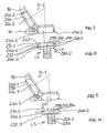
Das in Fig. 7 ausschnittsweise dargestellte Gehäuse 10.2
unterscheidet sich vom Gehäuse 10 durch eine etwas andere
Verzahnung 236.2 der in dem Gehäuse 10.2 einsitzenden Einsatzstücke
220.2 beziehungsweise des in das Gehäuse 10.2
einsetzbaren Einsatzstückes 226.2 (Fig. 8). Auch die Verzahnung
236.2 und damit auch das Einsatzstück 226.2 besitzt
jeweils zwei seitlich auskragende Vorsprünge 266.2 beziehungsweise
268.2. Im Gegensatz zum Einsatzstück 226 ist beim
Einsatzstück 226.2 und damit bei der Verzahnung 236.2 die
Seitenfläche 270.2 in gleicher Weise wie die jeweils gegenüberliegende
Seitenfläche 272 rechtwinklig zur Seitenwand
262 beziehungsweise 264 des quaderförmigen Körpers 260 ausgerichtet.
Die auskragende Länge L der beiden Vorsprünge
266.2 und 268.2 entspricht damit der Kraglänge LS jeder Seitenfläche
270.2 beziehungsweise 272. Für das Einsatzstück
226.2 und dessen Vorsprünge 266.2 beziehungsweise 268.2
beträgt die aufsummierte Kraglänge der jeweiligen beiden
Vorsprünge 266.2 beziehungsweise 268.2 dem Wert 4 LS. Dieser
Wert entspricht dem Wert 4 L. The detail shown in Fig. 7 housing 10.2
differs from the housing 10 by a slightly different
Gearing 236.2 of the in the housing 10.2 einitzenden inserts
220.2 or in the housing 10.2
usable insert 226.2 (Fig. 8). Also the gearing
236.2 and thus also the insert 226.2 has
two laterally projecting projections 266.2 respectively
268.2. In contrast to the
Das in Fig. 9 dargestellte Gehäuse 10.3 entspricht den vorstehend
beschriebenen Gehäusen mit dem Unterschied einer
andersartigen Verzahnung 236.3 zwischen dem jeweiligen Einsatzstück
220.3, 226.3 und der betreffenden Seitenwand 16.
Von dem quaderförmigen Körper 260 des Einsatzstückes 226.3
(Fig. 10) kragt seitlich jeweils ein einzelner im Querschnitt
schwalbenschwanzförmiger Vorsprung 266.3, 268.3 aus.
Dessen sich gegenüberliegende Seitenflächen 270.3, 272.3
sind schräg zur Längsachse 252 vorhanden. Ihre Länge LS ist
damit größer als die auskragende Länge L des betreffenden
Vorsprungs 266.3 beziehungsweise 268.3. Es gilt für jeden
Vorsprung, dass die beiden Längen LS größer sind als beide
Längen L.The housing 10.3 shown in Fig. 9 corresponds to the above
described housings with the difference of a
different teeth 236.3 between the respective insert
220.3, 226.3 and the
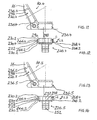
Bei dem Gehäuse 10.4 (Fig. 11) ist eine Verzahnung 236.4 vorhanden, die sich aus einem im Grundriß rechteckförmigen Vorsprung 266.2 (268.2) und einem dreieckförmigen Vorsprung 266.4 (268.4) zusammensetzt. Die seitlich sich gegenüberstehenden Seitenflächen 270.2 und 272 beim Vorsprung 266.2 sowie 270.2 und 270.4 beim Vorsprung 266.4 sind teilweise rechtwinklig (Seitenfläche 270.2, 272) beziehungsweise schräg (Seitenfläche 270.4) beim Einsatzstück 226.4 oder dem als Blindstopfen 220.4 ausgebildeten Einsatzstück ausgebildet. Die aufsummierte Länge aller auskragenden Seitenflächen der Vorsprünge auf einer Seite des quaderförmigen Körpers beträgt 3 L + LS und ist damit größer als 2 L.In the housing 10.4 (Fig. 11) is a toothing 236.4 present, consisting of a rectangular in plan Projection 266.2 (268.2) and a triangular projection 266.4 (268.4). The laterally facing ones Side surfaces 270.2 and 272 at the projection 266.2 as well as 270.2 and 270.4 at the lead 266.4 are partial right-angled (side surface 270.2, 272) respectively obliquely (side surface 270.4) at insert 226.4 or designed as blind plug 220.4 trained insert. The summed length of all protruding side surfaces the projections on one side of the cuboid body is 3 L + LS and is therefore greater than 2 L.
Auch bei der Verzahnung 236.5 (Fig. 13) des Gehäuses 10.5
ist zwischen dem Einsatzstück 220.5 beziehungsweise 226.5
und der betreffenden Seitenwand 16 dieses Gehäuses die aufsummierte
Kraglänge genauso groß wie bei der Verzahnung
236.4 gemäß Fig. 11 und 12. Der Unterschied besteht lediglich
darin, dass zwischen der schrägen Seitenfläche 270.4
des Vorsprungs 266.4 und der benachbarten, unter 90 Grad zur
Längsachse 252 ausgerichteten Seitenfläche 272 des benachbarten
Vorsprungs 266.2 eine in Längsrichtung verlaufende
Seitenfläche 273 vorhanden ist.Also in the teeth 236.5 (FIG. 13) of the housing 10.5
is between the insert 220.5 or 226.5
and the
Auch die in Fig. 15, 16 dargestellte Verzahnung 236.6 zwischen
einem Einsatzstück 220.6 beziehungsweise 226.6 und der
betreffenden Seitenwand 16 eines Gehäuses 10.6 weist diese
vorstehenden aufsummierten Kraglängen beziehungsweise Seitenwandlängen
von 3 L + LS auf. Im Unterschied zur Verzahnung
236.4 (Fig. 11, 12) liegt der im Querschnitt dreieckförmige
Vorsprung 266.4 mit seiner in der Zeichnung oberen
Seitenfläche 270.2 bündig zur Außenfläche des quaderförmigen
Körpers 260, während dies bei der Verzahnung 236.4 (Fig. 11,
12) nicht der Fall ist. Der dortige Vorsprung 266.4 besitzt
einen Rücksprung 290 zu der entsprechenden Außenwand des
quaderförmigen Körpers 260.Also, the teeth shown in Fig. 15, 16 236.6 between
an insert 220.6 or 226.6 and the
Die Verzahnung 236.7 beim Gehäuse 10.7 beziehungsweise der
in diese Gehäuse einsetzbaren Einsatzstücke 220.7 und 226.7
(Fig. 17, 18) besitzt jeweils zwei Vorsprünge 266.2, 268.2,
wie sie auch bei der Verzahnung 236.2 (Fig. 7, 8) vorhanden
sind. Der in der Zeichnung obere Vorsprung 266.2 beziehungsweise
268.2 der Verzahnung 236.7 ist bündig mit der Außenwand
des quaderförmigen Körpers 260, so wie dies ähnlich
auch bei der Verzahnung 236.6 (Fig. 15, 16) der Fall ist.
Demgegenüber ist bei der Verzahnung 236.2 gemäß Fig. 7, 8
ein durch eine Seitenwand 262 gebildeter Rücksprung zwischen
dem Vorsprung 266.2 und der Außenwand des quaderförmigen
Körpers 260 vorhanden. Bei der Verzahnung 236.7 ist eine
aufsummierte Länge der Vorsprünge wie bei der Verzahnung
236.2 in folgender Weise vorhanden: 4 L = 4 LS.The teeth 236.7 in the housing 10.7 or the
inserts 220.7 and 226.7 which can be inserted into these housings
(FIGS. 17, 18) each have two projections 266.2, 268.2,
as is also the case with the toothing 236.2 (FIGS. 7, 8)
are. The upper in the drawing projection 266.2 respectively
268.2 of the teeth 236.7 is flush with the outer wall
the
Die in Fig. 19 und 20 dargestellte Verzahnung 236.8 des
Gehäuses 10.8 besitzt eine Hammerkopfausbildung an dem
betreffenden Einsatzstück 220.8 beziehungsweise 226.8. Der
Vorsprung 266.8, 268.8 auf jeder der sich gegenüberliegenden
Seiten des quaderförmigen Körpers 260 besitzt eine in der
Zeichnung obere und untere jeweils einstufige Seitenflächenausbildung,
so dass jeder Vorsprung 266.8, 268.8 eine zweistufige
Verzahnung besitzt. Jede Verzahnung wird aus einer
stufenförmigen Seitenfläche 273 gebildet, deren durch die
Abwinklung auskragende Länge sich zusammensetzt aus
L/2 + T + L/2. Beide stufenförmigen Seitenwände 273 besitzen
damit aufsummiert eine Gesamtlänge von 2 L + 2 T. Dieses Maß
ist größer als 2 L.The teeth 236.8 shown in FIGS. 19 and 20 of the
Housing 10.8 has a hammerhead training on the
relevant insert 220.8 or 226.8. Of the
Projection 266.8, 268.8 on each of the opposite
Side of the
Die in Fig. 21, 22 dargestellte Verzahnung 236.9 des Gehäuses
10.9 ist pyramidenstumpfartig ausgebildet. Der einzige
Vorsprung 266.9, 268.9 des Einsatzstückes 226.9 besitzt sich
gegenüberliegende, schräg zur Längsachse 252 ausgerichtete
Seitenflächen 270.9 mit einer jeweiligen Länge LS. Die aufsummierten
Längen der auskragenden Seitenflächen eines Vorsprungs
besitzen damit das Längenmaß 2 LS. Dieses Maß ist
größer als der Wert 2 L. Für die Einsatzstücke 220.9, die in
den Seitenwänden 16 als Blindstopfen einsitzen, gilt entsprechendes.
Dies gilt im übrigen vergleichsweise für alle
vorstehenden Einsatzstücke 220. Die dargestellten Verzahnungen
gelten damit in gleicher Weise auch für entsprechende
Blindstopfen.The teeth shown in Fig. 21, 22 236.9 of the housing
10.9 is formed like a truncated pyramid. One and only
Projection 266.9, 268.9 of the insert 226.9 has
opposite, obliquely aligned to the
In einem Gehäuse können verschiedenartige Einsatzstücke vorhanden
sein. Dies betrifft einmal die Art des Einsatzstückes.
So kann das Einsatzstück als Blindstopfen oder als
Crimpflansch in dem Gehäuse einsitzen und dementsprechend
entweder zum Verschließen einer Öffnung 24, 26 oder zum
Durchführen eines Kabels durch eine Öffnung 24, 26 verwendet
werden. In einem Gehäuse können auch Einsatzstücke mit
unterschiedlichen Verzahnungen eingesetzt werden. Dies
bedingt dann aber entsprechend unterschiedliche Verzahnungen
in der Gehäusewand 16. Darüber hinaus ist es auch möglich,
Kabel mittels der vorstehend erwähnten Kabelschellen 56 in
dem Gehäuse 10 zu befestigen.In a housing, various inserts available
be. This concerns once the type of insert.
Thus, the insert as a blind plug or as
Insert the crimp flange in the housing and accordingly
either to close an
Auf den rechtwinklig zu den verzahnten Wänden des quaderförmigen
Körpers 260 vorhandenen beiden anderen Außenseiten
der Einsatzstücke 226, 220 ist jeweils eine auskragende
Querrippe 298 vorhanden. Die Querrippe 298 ist im vorliegenden
Fall nicht nur auf der in den Figuren sichtbaren Außenseite
296, sondern auch auf der dazu gegenüberliegenden
Außenseite des quaderförmigen Körpers 260 vorhanden. Diese
Querrippen stoßen einerseits auf den Boden 14 vom Unterteil
12 und andererseits von innen an das in der Zeichnung nicht
dargestellte Deckelteil an, das von oben auf dem Unterteil
12 und damit auch auf den Einsatzstücken 220 beziehungsweise
226 dicht anliegt. Die Einsatzstücke 220, 226 beziehungsweise
die vorstehend dargestellten, sich durch die jeweilige
Verzahnung unterscheidenden Einsatzstücke haben dadurch
nicht nur einen innigen Berührkontakt durch ihren durch die
jeweilige Verzahnung und die Längsrippen 280 bewirkten
Presssitz mit den Wänden 16, sondern auch eine spritzwasserdichte
Anlage an den übrigen den Einsatzstücken benachbarten
Wänden, nämlich dem Boden 14 und dem Deckelteil. Das Gehäuse
10 liegt also umlaufend dicht an den Außenflächen des Einsatzstückes
220 beziehungsweise 226 an.On the right-angled to the toothed walls of the
Claims (13)
- Housing (10) which is designed for screw connection to a mating housing (42), it being possible for a plug-in connector (28) to be inserted into the housing (10),characterized in thathaving a housing (10) made of solid metal,having at least one closable opening (24, 26) in the housing (10), through which, in the open state, it is possible to lead a cable which is to be connected to the plug-in connector (28),having a device for screwing the housing (10) to the collar (40) of the mating housing (42), this device projecting from the side wall (16) formed between the base (14) of the bottom part (12) and the cover part (20) of the housing, andhaving a coding device (30, 36, 38),the coding device (30, 36, 38) has a first projecting part (30), which projects away from at least one of the two mutually opposite side-wall regions (16.1, 16.2) of the side wall (16),this first projecting part (30) contains at least one through-bore (36, 38) for a coding part,the coding part is designed as a pin which can be plugged through the through-bore (36, 38) and, at the same time, can be inserted into a bore (36.1, 38.1) which is aligned with this through-bore (36, 38) in the collar (40) of the mating housing (42),a second projecting part (32) is provided on each of the two mutually opposite side-wall regions (16.1, 16.2) of the side wall (16), this projecting part being provided with a through-bore (46) for screwing the housing (10) to the collar (40) of the mating housing (42),the through-bore (36, 38) of the first projecting part (30) not being aligned with the through-bore (46) of the second projecting part (32).
- Housing according to Claim 1, characterized in thatthe first projecting part (30) projects on the side-wall region (16.1, 16.2) eccentrically in relation to the centre plane (34) of the housing (10).
- Housing according to Claim 2, characterized in thatthe first and second projecting parts (30, 32) are arranged eccentrically in relation to the centre plane (34) of the housing (10),the first projecting part (30) is provided on each side-wall region (16.1, 16.2) such that it is offset laterally and in height in relation to the second projecting part (32).
- Housing according to one of the preceding claims, characterized in thatthere is provided an insert component (220, 226) which can be inserted into the closable openings (24, 26) andis designed as a metallic dummy stopper (220), which closes the opening (24, 26), oris designed as a metallic cable fastening (226), which retains the cable on the housing (10) and can be inserted into the opening (24, 26),the respective insert component (220, 226) having protrusions (266, 268), which correspond with recesses in the housing (10) such that the insert component (220, 226) can be pushed into the housing (10) along these protrusions (266, 268), which constitute longitudinal guides for this insert component.
- Housing according to one of the preceding claims, characterized in thatthere are provided two screw-connection bores (50, 52) in which it is possible to screw-connect (60, 62) a cable clamp (56) with its two clamp ends within the housing.
- Housing according to Claim 5, characterized in thata screw-connection bore (50, 52) is provided for fastening an earthing conductor.
- Housing according to one of the preceding claims, characterized in thata multi-step toothing arrangement (236) is provided between the insert component (220, 226) and the housing (10) such thatthe side surfaces (270, 272) of the at least one protrusion (266, 268) which are provided transversely to the longitudinal axis of the housing openings each have a projecting length which, in total, is more than double the size of the length L of this protrusion which projects perpendicularly to the longitudinal axis of the housing opening.
- Housing according to Claim 7, characterized in thatat least one longitudinal rib (280) and/or one convexity is provided on the side surface (270, 272, 273) of a protrusion (266, 268).
- Housing according to either of Claims 7 and 8, characterized in thatat least two protrusions (266, 268) are provided on a side wall (262) of the insert component (220, 226).
- Housing according to Claim 9, characterized in thatone side surface (270) of one of the plurality of protrusions (266, 268) does not run parallel to the opposite side surface (272) of this protrusion.
- Housing according to one of Claims 7 to 10, characterized in thata protrusion (266.3, 268.3) is of dovetail-like or trapezoidal design in cross section.
- Housing according to Claim 7, characterized in thata transverse rib (298) is provided on at least one of the protrusion-free outer surface [sic] (296) of the insert component (220, 226).
- Housing according to Claim 12, characterized in thatthe transverse rib (298) extends over the entire outer side (296) of the body (260).
Applications Claiming Priority (2)
| Application Number | Priority Date | Filing Date | Title |
|---|---|---|---|
| DE29908277U | 1999-05-08 | ||
| DE29908277U DE29908277U1 (en) | 1999-05-08 | 1999-05-08 | Housing for connectors |
Publications (2)
| Publication Number | Publication Date |
|---|---|
| EP1052737A1 EP1052737A1 (en) | 2000-11-15 |
| EP1052737B1 true EP1052737B1 (en) | 2003-10-01 |
Family
ID=8073355
Family Applications (1)
| Application Number | Title | Priority Date | Filing Date |
|---|---|---|---|
| EP00109608A Expired - Lifetime EP1052737B1 (en) | 1999-05-08 | 2000-05-05 | Plug connector housing |
Country Status (3)
| Country | Link |
|---|---|
| EP (1) | EP1052737B1 (en) |
| AT (1) | ATE251350T1 (en) |
| DE (2) | DE29908277U1 (en) |
Cited By (1)
| Publication number | Priority date | Publication date | Assignee | Title |
|---|---|---|---|---|
| EP1995829A1 (en) | 2007-05-25 | 2008-11-26 | Fred R. Schmitt | Coding system for D-sub miniature connectors |
Families Citing this family (4)
| Publication number | Priority date | Publication date | Assignee | Title |
|---|---|---|---|---|
| EP1357643B1 (en) * | 2002-04-22 | 2010-07-21 | Fred R. Schmitt | Bus-Housing and insert parts for the cable openings of the Bus-housing |
| DE202004014562U1 (en) * | 2004-09-16 | 2004-11-18 | Schmitt, Fred R. | Housing for connectors |
| WO2009043862A1 (en) * | 2007-10-04 | 2009-04-09 | Nordia Innovation Ab | Connector cover |
| DE202015000163U1 (en) | 2015-01-15 | 2015-04-01 | Martin Danielczick | Device for fastening a connector housing to a front panel |
Family Cites Families (4)
| Publication number | Priority date | Publication date | Assignee | Title |
|---|---|---|---|---|
| US4842543A (en) * | 1988-06-03 | 1989-06-27 | Amp Incorporated | Contact protection system for electrical connectors |
| US5011436A (en) * | 1988-11-04 | 1991-04-30 | Amp Incorporated | Hermaphroditic keys |
| US4929184A (en) * | 1989-06-07 | 1990-05-29 | Amp Incorporated | Keyed electrical connectors with jackscrews |
| DE29801984U1 (en) * | 1998-02-06 | 1998-03-26 | Schmitt Fred R | Connector housing in 19 inch device system |
-
1999
- 1999-05-08 DE DE29908277U patent/DE29908277U1/en not_active Expired - Lifetime
-
2000
- 2000-05-05 AT AT00109608T patent/ATE251350T1/en active
- 2000-05-05 DE DE50003877T patent/DE50003877D1/en not_active Expired - Lifetime
- 2000-05-05 EP EP00109608A patent/EP1052737B1/en not_active Expired - Lifetime
Cited By (1)
| Publication number | Priority date | Publication date | Assignee | Title |
|---|---|---|---|---|
| EP1995829A1 (en) | 2007-05-25 | 2008-11-26 | Fred R. Schmitt | Coding system for D-sub miniature connectors |
Also Published As
| Publication number | Publication date |
|---|---|
| EP1052737A1 (en) | 2000-11-15 |
| DE29908277U1 (en) | 1999-07-22 |
| DE50003877D1 (en) | 2003-11-06 |
| ATE251350T1 (en) | 2003-10-15 |
Similar Documents
| Publication | Publication Date | Title |
|---|---|---|
| DE102006016882B4 (en) | Connectors | |
| DE102011115637B4 (en) | Electrical connection terminal | |
| AT503089B1 (en) | aTTACHMENT PART | |
| DE112009000065B4 (en) | harness | |
| DE19951455C1 (en) | Cable connection or connection device | |
| DE19625601B4 (en) | A plug connector assembly having a mechanism for confirming the fit of the connector housings and methods of attaching the connector housings | |
| DE102004038123B4 (en) | Electrical plug and electrical plug receptacle | |
| DE102007026582B3 (en) | Connector housing with a fixation for an electrical contact element and an electrical line | |
| DE10121654B4 (en) | Box-shaped contact with stress limitation | |
| DE4222452A1 (en) | SHIELDED CONNECTOR | |
| DE102007045400B4 (en) | power plug | |
| EP1052737B1 (en) | Plug connector housing | |
| EP0935314B9 (en) | Connector housing for 19 inch apparatus system | |
| EP1720222B1 (en) | Electrical connector, particularly for airbag ignition systems | |
| DE10022547C2 (en) | Cable connection or connection device | |
| DE4407083A1 (en) | Connecting plug | |
| DE102020109823A1 (en) | Discharge plug for a battery of an electric bike | |
| DE3607451A1 (en) | Device for fixing cables in cable entry stubs | |
| EP1124285B1 (en) | Appliance plug socket | |
| DE102020003770B4 (en) | Electric contact | |
| EP0838879A1 (en) | EMI-proof plug connector housing | |
| EP0915535B1 (en) | EMI proof connector housing and closing element for the cable openings | |
| EP1357643B1 (en) | Bus-Housing and insert parts for the cable openings of the Bus-housing | |
| DE2707254C2 (en) | Electric clutch | |
| DE102004006319B4 (en) | Airbag unit |
Legal Events
| Date | Code | Title | Description |
|---|---|---|---|
| PUAI | Public reference made under article 153(3) epc to a published international application that has entered the european phase |
Free format text: ORIGINAL CODE: 0009012 |
|
| AK | Designated contracting states |
Kind code of ref document: A1 Designated state(s): AT BE CH CY DE DK ES FI FR GB GR IE IT LI LU MC NL PT SE |
|
| AX | Request for extension of the european patent |
Free format text: AL;LT;LV;MK;RO;SI |
|
| 17P | Request for examination filed |
Effective date: 20010317 |
|
| 17Q | First examination report despatched |
Effective date: 20010515 |
|
| AKX | Designation fees paid |
Free format text: AT BE CH CY DE DK ES FI FR GB GR IE IT LI LU MC NL PT SE |
|
| GRAH | Despatch of communication of intention to grant a patent |
Free format text: ORIGINAL CODE: EPIDOS IGRA |
|
| GRAS | Grant fee paid |
Free format text: ORIGINAL CODE: EPIDOSNIGR3 |
|
| GRAA | (expected) grant |
Free format text: ORIGINAL CODE: 0009210 |
|
| AK | Designated contracting states |
Kind code of ref document: B1 Designated state(s): AT BE CH CY DE DK ES FI FR GB GR IE IT LI LU MC NL PT SE |
|
| PG25 | Lapsed in a contracting state [announced via postgrant information from national office to epo] |
Ref country code: IT Free format text: LAPSE BECAUSE OF FAILURE TO SUBMIT A TRANSLATION OF THE DESCRIPTION OR TO PAY THE FEE WITHIN THE PRE;WARNING: LAPSES OF ITALIAN PATENTS WITH EFFECTIVE DATE BEFORE 2007 MAY HAVE OCCURRED AT ANY TIME BEFORE 2007. THE CORRECT EFFECTIVE DATE MAY BE DIFFERENT FROM THE ONE RECORDED.SCRIBED TIME-LIMIT Effective date: 20031001 Ref country code: CY Free format text: LAPSE BECAUSE OF FAILURE TO SUBMIT A TRANSLATION OF THE DESCRIPTION OR TO PAY THE FEE WITHIN THE PRESCRIBED TIME-LIMIT Effective date: 20031001 Ref country code: FI Free format text: LAPSE BECAUSE OF FAILURE TO SUBMIT A TRANSLATION OF THE DESCRIPTION OR TO PAY THE FEE WITHIN THE PRESCRIBED TIME-LIMIT Effective date: 20031001 Ref country code: IE Free format text: LAPSE BECAUSE OF FAILURE TO SUBMIT A TRANSLATION OF THE DESCRIPTION OR TO PAY THE FEE WITHIN THE PRESCRIBED TIME-LIMIT Effective date: 20031001 |
|
| REG | Reference to a national code |
Ref country code: GB Ref legal event code: FG4D Free format text: NOT ENGLISH |
|
| REG | Reference to a national code |
Ref country code: CH Ref legal event code: EP |
|
| REG | Reference to a national code |
Ref country code: IE Ref legal event code: FG4D Free format text: GERMAN |
|
| REF | Corresponds to: |
Ref document number: 50003877 Country of ref document: DE Date of ref document: 20031106 Kind code of ref document: P |
|
| REG | Reference to a national code |
Ref country code: CH Ref legal event code: NV Representative=s name: ING. MARCO ZARDI C/O M. ZARDI & CO. S.A. |
|
| PG25 | Lapsed in a contracting state [announced via postgrant information from national office to epo] |
Ref country code: DK Free format text: LAPSE BECAUSE OF FAILURE TO SUBMIT A TRANSLATION OF THE DESCRIPTION OR TO PAY THE FEE WITHIN THE PRESCRIBED TIME-LIMIT Effective date: 20040101 Ref country code: GR Free format text: LAPSE BECAUSE OF FAILURE TO SUBMIT A TRANSLATION OF THE DESCRIPTION OR TO PAY THE FEE WITHIN THE PRESCRIBED TIME-LIMIT Effective date: 20040101 |
|
| PG25 | Lapsed in a contracting state [announced via postgrant information from national office to epo] |
Ref country code: ES Free format text: LAPSE BECAUSE OF FAILURE TO SUBMIT A TRANSLATION OF THE DESCRIPTION OR TO PAY THE FEE WITHIN THE PRESCRIBED TIME-LIMIT Effective date: 20040112 |
|
| REG | Reference to a national code |
Ref country code: SE Ref legal event code: TRGR |
|
| GBT | Gb: translation of ep patent filed (gb section 77(6)(a)/1977) |
Effective date: 20040118 |
|
| PG25 | Lapsed in a contracting state [announced via postgrant information from national office to epo] |
Ref country code: LU Free format text: LAPSE BECAUSE OF NON-PAYMENT OF DUE FEES Effective date: 20040505 |
|
| PG25 | Lapsed in a contracting state [announced via postgrant information from national office to epo] |
Ref country code: BE Free format text: LAPSE BECAUSE OF NON-PAYMENT OF DUE FEES Effective date: 20040531 Ref country code: MC Free format text: LAPSE BECAUSE OF NON-PAYMENT OF DUE FEES Effective date: 20040531 |
|
| REG | Reference to a national code |
Ref country code: IE Ref legal event code: FD4D |
|
| ET | Fr: translation filed | ||
| PLBE | No opposition filed within time limit |
Free format text: ORIGINAL CODE: 0009261 |
|
| STAA | Information on the status of an ep patent application or granted ep patent |
Free format text: STATUS: NO OPPOSITION FILED WITHIN TIME LIMIT |
|
| 26N | No opposition filed |
Effective date: 20040702 |
|
| BERE | Be: lapsed |
Owner name: *SCHMITT FRED Effective date: 20040531 |
|
| REG | Reference to a national code |
Ref country code: CH Ref legal event code: PCAR Free format text: ISLER & PEDRAZZINI AG;POSTFACH 1772;8027 ZUERICH (CH) |
|
| PG25 | Lapsed in a contracting state [announced via postgrant information from national office to epo] |
Ref country code: PT Free format text: LAPSE BECAUSE OF NON-PAYMENT OF DUE FEES Effective date: 20040301 |
|
| REG | Reference to a national code |
Ref country code: FR Ref legal event code: PLFP Year of fee payment: 17 |
|
| REG | Reference to a national code |
Ref country code: FR Ref legal event code: PLFP Year of fee payment: 18 |
|
| REG | Reference to a national code |
Ref country code: DE Ref legal event code: R082 Ref document number: 50003877 Country of ref document: DE Representative=s name: PATENTANWAELTE DR.-ING. GERHARD CLEMENS, DR. R, DE Ref country code: DE Ref legal event code: R081 Ref document number: 50003877 Country of ref document: DE Owner name: INOTEC ELECTRONICS GMBH, DE Free format text: FORMER OWNER: SCHMITT, FRED R., 74388 TALHEIM, DE |
|
| REG | Reference to a national code |
Ref country code: CH Ref legal event code: PUE Owner name: INOTEC ELECTRONICS GMBH, DE Free format text: FORMER OWNER: SCHMITT, FRED, DE |
|
| REG | Reference to a national code |
Ref country code: GB Ref legal event code: 732E Free format text: REGISTERED BETWEEN 20180412 AND 20180418 |
|
| REG | Reference to a national code |
Ref country code: FR Ref legal event code: PLFP Year of fee payment: 19 |
|
| PGFP | Annual fee paid to national office [announced via postgrant information from national office to epo] |
Ref country code: NL Payment date: 20190521 Year of fee payment: 20 |
|
| PGFP | Annual fee paid to national office [announced via postgrant information from national office to epo] |
Ref country code: DE Payment date: 20190514 Year of fee payment: 20 |
|
| PGFP | Annual fee paid to national office [announced via postgrant information from national office to epo] |
Ref country code: FR Payment date: 20190521 Year of fee payment: 20 Ref country code: SE Payment date: 20190523 Year of fee payment: 20 |
|
| PGFP | Annual fee paid to national office [announced via postgrant information from national office to epo] |
Ref country code: CH Payment date: 20190523 Year of fee payment: 20 |
|
| PGFP | Annual fee paid to national office [announced via postgrant information from national office to epo] |
Ref country code: GB Payment date: 20190523 Year of fee payment: 20 Ref country code: AT Payment date: 20190517 Year of fee payment: 20 |
|
| REG | Reference to a national code |
Ref country code: DE Ref legal event code: R071 Ref document number: 50003877 Country of ref document: DE |
|
| REG | Reference to a national code |
Ref country code: NL Ref legal event code: MK Effective date: 20200504 |
|
| REG | Reference to a national code |
Ref country code: CH Ref legal event code: PL |
|
| REG | Reference to a national code |
Ref country code: GB Ref legal event code: PE20 Expiry date: 20200504 |
|
| REG | Reference to a national code |
Ref country code: SE Ref legal event code: EUG |
|
| REG | Reference to a national code |
Ref country code: AT Ref legal event code: MK07 Ref document number: 251350 Country of ref document: AT Kind code of ref document: T Effective date: 20200505 |
|
| PG25 | Lapsed in a contracting state [announced via postgrant information from national office to epo] |
Ref country code: GB Free format text: LAPSE BECAUSE OF EXPIRATION OF PROTECTION Effective date: 20200504 |