DE102007045400B4 - power plug - Google Patents
power plug Download PDFInfo
- Publication number
- DE102007045400B4 DE102007045400B4 DE200710045400 DE102007045400A DE102007045400B4 DE 102007045400 B4 DE102007045400 B4 DE 102007045400B4 DE 200710045400 DE200710045400 DE 200710045400 DE 102007045400 A DE102007045400 A DE 102007045400A DE 102007045400 B4 DE102007045400 B4 DE 102007045400B4
- Authority
- DE
- Germany
- Prior art keywords
- plug
- socket
- power
- pins
- cable
- Prior art date
- Legal status (The legal status is an assumption and is not a legal conclusion. Google has not performed a legal analysis and makes no representation as to the accuracy of the status listed.)
- Active
Links
Classifications
-
- H—ELECTRICITY
- H01—ELECTRIC ELEMENTS
- H01R—ELECTRICALLY-CONDUCTIVE CONNECTIONS; STRUCTURAL ASSOCIATIONS OF A PLURALITY OF MUTUALLY-INSULATED ELECTRICAL CONNECTING ELEMENTS; COUPLING DEVICES; CURRENT COLLECTORS
- H01R24/00—Two-part coupling devices, or either of their cooperating parts, characterised by their overall structure
- H01R24/28—Coupling parts carrying pins, blades or analogous contacts and secured only to wire or cable
- H01R24/30—Coupling parts carrying pins, blades or analogous contacts and secured only to wire or cable with additional earth or shield contacts
-
- H—ELECTRICITY
- H01—ELECTRIC ELEMENTS
- H01R—ELECTRICALLY-CONDUCTIVE CONNECTIONS; STRUCTURAL ASSOCIATIONS OF A PLURALITY OF MUTUALLY-INSULATED ELECTRICAL CONNECTING ELEMENTS; COUPLING DEVICES; CURRENT COLLECTORS
- H01R13/00—Details of coupling devices of the kinds covered by groups H01R12/70 or H01R24/00 - H01R33/00
- H01R13/46—Bases; Cases
- H01R13/502—Bases; Cases composed of different pieces
- H01R13/504—Bases; Cases composed of different pieces different pieces being moulded, cemented, welded, e.g. ultrasonic, or swaged together
-
- H—ELECTRICITY
- H01—ELECTRIC ELEMENTS
- H01R—ELECTRICALLY-CONDUCTIVE CONNECTIONS; STRUCTURAL ASSOCIATIONS OF A PLURALITY OF MUTUALLY-INSULATED ELECTRICAL CONNECTING ELEMENTS; COUPLING DEVICES; CURRENT COLLECTORS
- H01R13/00—Details of coupling devices of the kinds covered by groups H01R12/70 or H01R24/00 - H01R33/00
- H01R13/56—Means for preventing chafing or fracture of flexible leads at outlet from coupling part
- H01R13/567—Traverse cable outlet or wire connection
-
- H—ELECTRICITY
- H01—ELECTRIC ELEMENTS
- H01R—ELECTRICALLY-CONDUCTIVE CONNECTIONS; STRUCTURAL ASSOCIATIONS OF A PLURALITY OF MUTUALLY-INSULATED ELECTRICAL CONNECTING ELEMENTS; COUPLING DEVICES; CURRENT COLLECTORS
- H01R13/00—Details of coupling devices of the kinds covered by groups H01R12/70 or H01R24/00 - H01R33/00
- H01R13/648—Protective earth or shield arrangements on coupling devices, e.g. anti-static shielding
- H01R13/655—Protective earth or shield arrangements on coupling devices, e.g. anti-static shielding with earth brace
-
- H—ELECTRICITY
- H01—ELECTRIC ELEMENTS
- H01R—ELECTRICALLY-CONDUCTIVE CONNECTIONS; STRUCTURAL ASSOCIATIONS OF A PLURALITY OF MUTUALLY-INSULATED ELECTRICAL CONNECTING ELEMENTS; COUPLING DEVICES; CURRENT COLLECTORS
- H01R4/00—Electrically-conductive connections between two or more conductive members in direct contact, i.e. touching one another; Means for effecting or maintaining such contact; Electrically-conductive connections having two or more spaced connecting locations for conductors and using contact members penetrating insulation
- H01R4/28—Clamped connections, spring connections
- H01R4/30—Clamped connections, spring connections utilising a screw or nut clamping member
- H01R4/36—Conductive members located under tip of screw
-
- H—ELECTRICITY
- H01—ELECTRIC ELEMENTS
- H01R—ELECTRICALLY-CONDUCTIVE CONNECTIONS; STRUCTURAL ASSOCIATIONS OF A PLURALITY OF MUTUALLY-INSULATED ELECTRICAL CONNECTING ELEMENTS; COUPLING DEVICES; CURRENT COLLECTORS
- H01R9/00—Structural associations of a plurality of mutually-insulated electrical connecting elements, e.g. terminal strips or terminal blocks; Terminals or binding posts mounted upon a base or in a case; Bases therefor
- H01R9/22—Bases, e.g. strip, block, panel
- H01R9/226—Bases, e.g. strip, block, panel comprising a plurality of conductive flat strips providing connection between wires or components
-
- H—ELECTRICITY
- H01—ELECTRIC ELEMENTS
- H01R—ELECTRICALLY-CONDUCTIVE CONNECTIONS; STRUCTURAL ASSOCIATIONS OF A PLURALITY OF MUTUALLY-INSULATED ELECTRICAL CONNECTING ELEMENTS; COUPLING DEVICES; CURRENT COLLECTORS
- H01R2103/00—Two poles
Abstract
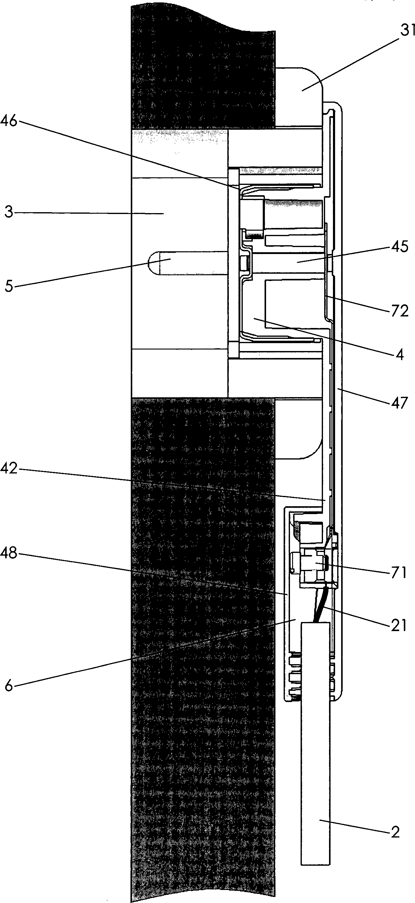
Netzstecker (1) zum Anschluss eines Netzkabels (2) an eine Schutzkontaktsteckdose (3), umfassend ein Steckerteil (4), in dem Steckerstifte (5) angeordnet sind, und einen Kabelanschlussraum (6), der mit dem Steckerteil (4) verbunden ist, dadurch gekennzeichnet, dass der Kabelanschlussraum (6) nach bestimmungsgemäßen Einstecken des Steckerteils (4) in eine Schutzkontaktsteckdose (3) seitlich zur Schutzkontaktsteckdose (3) angeordnet ist, und dass der Kabelanschlussraum (6) den durch den Rahmen (31) der Steckdose (3) geschaffenen Raum nutzt.Power plug (1) for connecting a power cable (2) to a safety socket (3), comprising a plug part (4) in which plug pins (5) are arranged, and a cable connection space (6) which is connected to the plug part (4) , characterized in that the cable connection space (6) after proper insertion of the plug part (4) in a safety socket (3) is arranged laterally to the grounded socket (3), and that the cable connection space (6) through the frame (31) of the socket ( 3) uses created space.
Description
Die Erfindung betrifft einen Netzstecker nach dem Oberbegriff des Patentanspruchs 1.The The invention relates to a power plug according to the preamble of the claim 1.
Netzstecker der hier betrachteten Art sind unter der Bezeichnung Konturenstecker oder bei Fehlen eines Schutzkontaktes als Eurostecker bekannt. Mit ihnen können Geräte der Schutzklasse I und der Klasse II an das Stromnetz angeschlossen werden. Die Stecker sind wiederanschließbar, oder bei der nichtwiederanschließbaren Ausführung voll mit Kunststoff umspritzt. Typische Anwendungsgebiete der Stecker sind Geräte, wie beispielsweise Radios, Lampen, Staubsauger, u. dgl.power plug The type considered here are under the name contour plug or in the absence of a protective contact known as Euro plug. With you can equipment Class I and Class II are connected to the mains. The plugs are reconnectable, or in the nichtwiederanschließbaren execution fully encapsulated in plastic. Typical applications of the plug are devices, such as radios, Lamps, vacuum cleaners, u. like.
Bei den bekannten Steckern besteht ein Problem darin, dass das aus dem Stecker herausgeführte Kabel über die jeweilige Steckdose hervorsteht. Dies ist durch den Anschluss der Kabel an die Steckerstifte hervorgerufen. Da der gesamte Stecker bis zum isolierten Kabel, welches zum Verbraucher führt, mit einem Gehäuse isoliert ist, hat der Stecker in unmittelbarer Nähe zum Steckerteil, welches in eingestecktem Zustand in die Steckdosenvertiefung eintaucht, eine große Bauhöhe. Dies ist sowohl bei Steckern der Fall, bei denen das Kabel in axialer Verlängerung der Steckerstifte aus dem Gehäuse herausgeführt ist, als auch bei Steckern, bei denen das Kabel rechtwinklig zur Anordnung der Steckerstifte aus dem Gehäuse herausgeführt ist. Die große Bauhöhe resultiert aus der Anordnung des Kabelanschlussraums, also des Raums, in dem das dreiadrige Netzkabel endet und die Anschlussdrähte mit den Steckerstiften verbunden sind.at the known plugs is a problem in that from the Plug led out Cable over the respective socket protrudes. This is through the connection the cable caused to the pins. Because the entire plug to the insulated cable, which leads to the consumer, with a housing is isolated, the plug has in close proximity to the plug part, which dips into the socket recess when plugged in a big Height. This is the case with plugs where the cable is in axial renewal the pins from the housing led out is, as well as with plugs, where the cable is perpendicular to the Arrangement of the connector pins is led out of the housing. The size Height results from the arrangement of the cable connection space, so the room in which the three-core power cord ends and the connecting wires with the plug pins are connected.
So
ist beispielsweise aus der
Dies hat zur Folge, dass an die Steckdose heranreichende Möbelstücke oder Geräte einen Abstand zur Steckdose und damit zur Wand aufweisen müssen, der mindestens der Bauhöhe des Gehäuses des Steckers entspricht. Da aus optischen Gründen die Möbelstücke oder Geräte in vielen Fällen so dicht wie möglich an die Steckdose/die Wand heranragen sollen, wird bei den Steckern, bei denen die Kabel koaxial zu den Steckerstiften aus dem Gehäuse heraus geführt sind, ein Abknicken des Kabels in Kauf genommen. Dies beinhaltet ein nicht unerhebliches Risiko, da es hierdurch zu Beschädigungen der Isolierungen kommen kann, die eine sichere Betätigung des Steckers negativ beeinträchtigen kann. Zur Vermeidung dieser Gefahr werden daher oftmals in die Rückwand des jeweiligen Möbelstücks Löcher eingebracht, was mit zusätzlichen Kosten verbunden ist und eine Beschädigung des Möbelstücks bedeutet. Soweit Geräte unmittelbar an die Wand heranragen sollen, ist jedoch auch diese Abhilfemöglichkeit ausgeschlossen.This As a result, to the outlet zooming furniture or equipment must have a distance from the socket and thus to the wall, the at least the height of the housing of the Plug corresponds. Because of visual reasons, the furniture or appliances in many make as close as possible to stand at the socket / the wall, is at the plugs, in which the cables are led out of the housing coaxially with the plug pins, a kinking of the cable accepted. This does not include one negligible risk, as this will damage the insulation That can be a safe operation of the Adversely affect connector can. To avoid this danger are therefore often in the back wall of the each piece of furniture introduced holes, what with additional Costs associated and damage to the furniture means. So far equipment However, this is also meant to be directly on the wall Remedy possibility locked out.
Zur
Beseitigung dieses Problems schlägt
die
Aufgabe der Erfindung ist es, einen Netzstecker zu schaffen, der eine sehr geringe Bauhöhe aufweist und der in herkömmlichen Steckdosen einsetzbar ist. Gemäß der Erfindung wird diese Aufgabe durch die Merkmale des Patentanspruchs 1 gelöst.task The invention is to provide a power plug, which is a very low height and in conventional Sockets can be used. According to the invention This object is achieved by the features of claim 1.
Mit der Erfindung ist ein Netzstecker zum Anschluss eines Netzkabels an eine Schutzkontaktsteckdose geschaffen, der eine sehr geringe Bauhöhe aufweist. Durch die seitlich beabstandete Anordnung des Kabelanschlussraums zum Rahmen der Steckdose besteht die Möglichkeit, die Höhe des Gehäuses im Wesentlichen lediglich abhängig von der Tiefe der Steckeraufnahmevertiefung der Steckdose auszubilden. Es ragt daher das Gehäuse lediglich um eine Höhe über die Steckdose hinaus, die eine Verbindung der elektrischen Leiter zwischen Steckerstiften und Kabelanschlussraum ermöglicht. Aufgrund der Bau höhe üblicher Steckdosen ist gleichzeitig durch die seitliche Anordnung ein ausreichender Bauraum für die Verwirklichung des Kabelanschlussraums geschaffen.With The invention is a power plug for connecting a power cable created to a socket with a very low height having. Due to the laterally spaced arrangement of the cable connection space to the frame of the socket there is the possibility of the height of the housing in the Essentially merely dependent from the depth of the plug receiving recess of the socket. It therefore protrudes the case only one height above the Outlet that connects the electrical conductor between Plug pins and cable connection space allows. Due to the construction height usual Sockets is at the same time by the lateral arrangement sufficient space for the Realization of the cable connection space created.
In Weiterbildung der Erfindung ist der Kabelanschlussraum mit den Steckerstiften über Kontaktbleche verbunden. Durch die Verwendung von Kontaktblechen ist eine sehr geringe Bauhöhe realisierbar. Gleichzeitig bietet die Verwendung von Kontaktblechen die Möglichkeit einer einfachen und zugleich zuverlässigen Verbindung mit den Steckerstiften und dem Niet einerseits und den Anschlussdrähten andererseits, was die Montage vereinfacht und die Haltbarkeit des lösungsgemäßen Netzsteckers erhöht.In Further development of the invention is the cable connection compartment with the connector pins via contact plates connected. By using contact sheets is a very low height realizable. At the same time provides the use of contact plates the possibility a simple yet reliable connection to the pins and the rivet on the one hand and the connecting wires on the other hand, what the Installation simplified and increases the durability of the solution according to the mains plug.
In anderer Weiterbildung der Erfindung sind auf der der Schutzkontaktsteckdose abgewandten Seite des Steckerteils Bilder, Piktogramme oder sonstige Angaben anbringbar. Es ist somit die Möglichkeit geschaffen, großflächig Kennzeichnungen für den Verbraucher auf dem Netzstecker vorzusehen, die für den Verbraucher leicht zu erkennen sind. Dies stellt insbesondere für Anwendungs- und Warnhinweise eine deutliche Verbesserung der Informationsübermittlung dar.In Another embodiment of the invention are on the grounded socket opposite side of the plug part pictures, pictograms or other Details attachable. It is thus created the possibility of large area markings for the Provide consumers on the power plug that is for the consumer easy to recognize. This represents in particular for application and warning notices a significant improvement in the transmission of information.
Andere Weiterbildungen und Ausgestaltungen der Erfindung sind in den übrigen Unteransprüchen angegeben. Ein Ausführungsbeispiel der Erfindung ist in der Zeichnung dargestellt und wird nachfolgend im Einzelnen beschrieben. Es zeigen:Other Further developments and refinements of the invention are specified in the remaining subclaims. An embodiment The invention is illustrated in the drawing and will be described below described in detail. Show it:
Der
als Ausführungsbeispiel
gewählte
Netzstecker
Das
Steckerteil
Die
Platte
Das
Steckerteil
Die
Steckerstifte
Die
Verbindung der Steckerstifte
Im
Ausführungsbeispiel
nach den
Bei
dem Ausführungsbeispiel
nach
Der
lösungsgemäße Netzstecker
ist in seiner Bauweise hinsichtlich der Bauhöhe außerordentlich kompakt ausgestaltet.
Da die Steckerstifte
Claims (9)
Priority Applications (2)
| Application Number | Priority Date | Filing Date | Title |
|---|---|---|---|
| DE202007019214U DE202007019214U1 (en) | 2007-09-21 | 2007-09-21 | power plug |
| DE200710045400 DE102007045400B4 (en) | 2007-09-21 | 2007-09-21 | power plug |
Applications Claiming Priority (1)
| Application Number | Priority Date | Filing Date | Title |
|---|---|---|---|
| DE200710045400 DE102007045400B4 (en) | 2007-09-21 | 2007-09-21 | power plug |
Publications (2)
| Publication Number | Publication Date |
|---|---|
| DE102007045400A1 DE102007045400A1 (en) | 2009-04-23 |
| DE102007045400B4 true DE102007045400B4 (en) | 2010-06-10 |
Family
ID=40458600
Family Applications (2)
| Application Number | Title | Priority Date | Filing Date |
|---|---|---|---|
| DE202007019214U Expired - Lifetime DE202007019214U1 (en) | 2007-09-21 | 2007-09-21 | power plug |
| DE200710045400 Active DE102007045400B4 (en) | 2007-09-21 | 2007-09-21 | power plug |
Family Applications Before (1)
| Application Number | Title | Priority Date | Filing Date |
|---|---|---|---|
| DE202007019214U Expired - Lifetime DE202007019214U1 (en) | 2007-09-21 | 2007-09-21 | power plug |
Country Status (1)
| Country | Link |
|---|---|
| DE (2) | DE202007019214U1 (en) |
Cited By (2)
| Publication number | Priority date | Publication date | Assignee | Title |
|---|---|---|---|---|
| DE202013001536U1 (en) | 2013-02-19 | 2013-02-27 | Sygonix GmbH | power plug |
| KR20220065508A (en) | 2020-11-13 | 2022-05-20 | 엘지전자 주식회사 | Power plug and home appliance including the same |
Families Citing this family (4)
| Publication number | Priority date | Publication date | Assignee | Title |
|---|---|---|---|---|
| US8608514B2 (en) * | 2012-01-26 | 2013-12-17 | Emerson Electric Co. | Connector block with parallel electrical connection |
| DE102012011299A1 (en) | 2012-06-10 | 2013-12-12 | Axel R. Hidde | Comfort flat plug e.g. power plug for household and workshop equipment, has pivot bearing that is formed with handle recess, such that distance from pivot bearing is about one-third distance of grip to bearing in recess |
| DE202012006667U1 (en) | 2012-06-10 | 2012-09-17 | Axel R. Hidde | Comfort tabs |
| DE202015007800U1 (en) | 2015-11-13 | 2015-12-15 | Axel R. Hidde | Comfort plug as adapter |
Citations (3)
| Publication number | Priority date | Publication date | Assignee | Title |
|---|---|---|---|---|
| DE871912C (en) * | 1950-09-14 | 1953-03-26 | Busch Jaeger Luedenscheider Me | Three-pole or multi-pole plug with protective contact on the side |
| DE202004010863U1 (en) * | 2004-07-12 | 2004-11-11 | GEM TERMINAL IND. CO., LTD., Lu-Chu Hsiang | Inner frame of plug has strengthening rib between outside of female connector, main body to strengthen female connector wall to prevent deformation by high temperature, pressure of injection molding |
| DE102004022189A1 (en) * | 2004-04-20 | 2005-11-24 | Werner Schnabel | Wall outlet socket for a flush-mounted safety contact plug has a plug case integrated in a masking frame for retaining a plug with a positive fit |
-
2007
- 2007-09-21 DE DE202007019214U patent/DE202007019214U1/en not_active Expired - Lifetime
- 2007-09-21 DE DE200710045400 patent/DE102007045400B4/en active Active
Patent Citations (3)
| Publication number | Priority date | Publication date | Assignee | Title |
|---|---|---|---|---|
| DE871912C (en) * | 1950-09-14 | 1953-03-26 | Busch Jaeger Luedenscheider Me | Three-pole or multi-pole plug with protective contact on the side |
| DE102004022189A1 (en) * | 2004-04-20 | 2005-11-24 | Werner Schnabel | Wall outlet socket for a flush-mounted safety contact plug has a plug case integrated in a masking frame for retaining a plug with a positive fit |
| DE202004010863U1 (en) * | 2004-07-12 | 2004-11-11 | GEM TERMINAL IND. CO., LTD., Lu-Chu Hsiang | Inner frame of plug has strengthening rib between outside of female connector, main body to strengthen female connector wall to prevent deformation by high temperature, pressure of injection molding |
Cited By (3)
| Publication number | Priority date | Publication date | Assignee | Title |
|---|---|---|---|---|
| DE202013001536U1 (en) | 2013-02-19 | 2013-02-27 | Sygonix GmbH | power plug |
| EP2768090A1 (en) | 2013-02-19 | 2014-08-20 | Sygonix GmbH | Plug |
| KR20220065508A (en) | 2020-11-13 | 2022-05-20 | 엘지전자 주식회사 | Power plug and home appliance including the same |
Also Published As
| Publication number | Publication date |
|---|---|
| DE202007019214U1 (en) | 2011-02-24 |
| DE102007045400A1 (en) | 2009-04-23 |
Similar Documents
| Publication | Publication Date | Title |
|---|---|---|
| EP3164911B1 (en) | Plug | |
| DE102009010492B3 (en) | Cable organizer Insert for connectors | |
| EP2107648B1 (en) | Connector with a shielding-screen support | |
| DE102007045400B4 (en) | power plug | |
| DE102012100815B3 (en) | Electrical coupling element | |
| DE3135173C2 (en) | Installation part designed as an electrical plug or as a socket or as a coupling socket | |
| DE102010022690B4 (en) | Electrical connector with PE contact | |
| EP2888787A1 (en) | Plug connector with an earth terminal for at least one lead | |
| DE102016005508A1 (en) | High-voltage connector | |
| DE20213312U1 (en) | Connector for connecting an electrical cable | |
| DE19525801C2 (en) | Device for the electrically conductive connection of two electrical lines | |
| DE202011050660U1 (en) | Protective housing for an electrical connector | |
| EP1052737B1 (en) | Plug connector housing | |
| EP0930673B1 (en) | Transformer device and connector assembly | |
| DE102008057473B4 (en) | Grommet | |
| EP1355379B1 (en) | Plug connector with insulation displacement contacts | |
| EP3412965A1 (en) | Integrated lights | |
| DE102011090209B4 (en) | Electrical connection device | |
| DE102017131062B3 (en) | socket | |
| DE102008028521B4 (en) | Electrical plug device | |
| DE102008028516B4 (en) | Electrical plug device | |
| DE102008028518B4 (en) | Electrical plug device | |
| DE3011762C2 (en) | Multipole collar connector | |
| DE202015102508U1 (en) | Installation box and installation system | |
| DE102022106629A1 (en) | Power plug |
Legal Events
| Date | Code | Title | Description |
|---|---|---|---|
| OP8 | Request for examination as to paragraph 44 patent law | ||
| 8363 | Opposition against the patent | ||
| R138 | Derivation of utility model |
Ref document number: 202007019214 Country of ref document: DE |
|
| R079 | Amendment of ipc main class |
Free format text: PREVIOUS MAIN CLASS: H01R0024080000 Ipc: H01R0024300000 Effective date: 20110704 Free format text: PREVIOUS MAIN CLASS: H01R0024080000 Ipc: H01R0024300000 |
|
| R006 | Appeal filed | ||
| R008 | Case pending at federal patent court | ||
| R010 | Appeal proceedings settled by withdrawal of appeal(s) or in some other way | ||
| R008 | Case pending at federal patent court | ||
| R039 | Revocation action filed |
Effective date: 20130131 |
|
| R031 | Decision of examining division/federal patent court maintaining patent unamended now final |
Effective date: 20120810 Effective date: 20130411 |
|
| R020 | Patent grant now final | ||
| R040 | Withdrawal/refusal of revocation action now final | ||
| R040 | Withdrawal/refusal of revocation action now final |
Effective date: 20141008 |