EP1052662A2 - Schalter für Fahrzeuge - Google Patents
Schalter für Fahrzeuge Download PDFInfo
- Publication number
- EP1052662A2 EP1052662A2 EP00109368A EP00109368A EP1052662A2 EP 1052662 A2 EP1052662 A2 EP 1052662A2 EP 00109368 A EP00109368 A EP 00109368A EP 00109368 A EP00109368 A EP 00109368A EP 1052662 A2 EP1052662 A2 EP 1052662A2
- Authority
- EP
- European Patent Office
- Prior art keywords
- battery
- connection
- contact
- vehicle
- electrical system
- Prior art date
- Legal status (The legal status is an assumption and is not a legal conclusion. Google has not performed a legal analysis and makes no representation as to the accuracy of the status listed.)
- Granted
Links
Images
Classifications
-
- H—ELECTRICITY
- H01—ELECTRIC ELEMENTS
- H01H—ELECTRIC SWITCHES; RELAYS; SELECTORS; EMERGENCY PROTECTIVE DEVICES
- H01H1/00—Contacts
- H01H1/12—Contacts characterised by the manner in which co-operating contacts engage
- H01H1/36—Contacts characterised by the manner in which co-operating contacts engage by sliding
-
- H—ELECTRICITY
- H01—ELECTRIC ELEMENTS
- H01H—ELECTRIC SWITCHES; RELAYS; SELECTORS; EMERGENCY PROTECTIVE DEVICES
- H01H1/00—Contacts
- H01H1/12—Contacts characterised by the manner in which co-operating contacts engage
- H01H1/36—Contacts characterised by the manner in which co-operating contacts engage by sliding
- H01H1/365—Bridging contacts
-
- H—ELECTRICITY
- H02—GENERATION; CONVERSION OR DISTRIBUTION OF ELECTRIC POWER
- H02J—ELECTRIC POWER NETWORKS; CIRCUIT ARRANGEMENTS OR SYSTEMS FOR SUPPLYING OR DISTRIBUTING ELECTRIC POWER; SYSTEMS FOR STORING ELECTRIC ENERGY
- H02J7/00—Circuit arrangements for charging or discharging batteries or for supplying loads from batteries
- H02J7/60—Circuit arrangements for charging or discharging batteries or for supplying loads from batteries including safety or protection arrangements
- H02J7/63—Circuit arrangements for charging or discharging batteries or for supplying loads from batteries including safety or protection arrangements against overdischarge
-
- H—ELECTRICITY
- H02—GENERATION; CONVERSION OR DISTRIBUTION OF ELECTRIC POWER
- H02J—ELECTRIC POWER NETWORKS; CIRCUIT ARRANGEMENTS OR SYSTEMS FOR SUPPLYING OR DISTRIBUTING ELECTRIC POWER; SYSTEMS FOR STORING ELECTRIC ENERGY
- H02J7/00—Circuit arrangements for charging or discharging batteries or for supplying loads from batteries
- H02J7/60—Circuit arrangements for charging or discharging batteries or for supplying loads from batteries including safety or protection arrangements
- H02J7/663—Circuit arrangements for charging or discharging batteries or for supplying loads from batteries including safety or protection arrangements using battery or load disconnect circuits
-
- H—ELECTRICITY
- H01—ELECTRIC ELEMENTS
- H01H—ELECTRIC SWITCHES; RELAYS; SELECTORS; EMERGENCY PROTECTIVE DEVICES
- H01H1/00—Contacts
- H01H1/58—Electric connections to or between contacts; Terminals
- H01H2001/5877—Electric connections to or between contacts; Terminals with provisions for direct mounting on a battery pole
Definitions
- the invention relates to a switch for vehicles according to the preamble of claim 1.
- a vehicle with such a drained battery is often put back into operation by an external start, so leave it on, and do it by adding a second one Battery, usually from a third-party vehicle comes, parallel to the discharged vehicle battery is switched. It is not uncommon here, however, especially at night, for a mix-up the Pole, whereby not only the already weakened anyway Vehicle battery, but also the electrical Devices and control devices in the vehicle, in other words, the entire vehicle electrical system, including the generator and generator diodes as well as the electronics sustained damage.
- the invention is therefore based on the object To prevent over-discharge of a vehicle battery while ensuring that in the event of a Reverse polarity is required if jump-starting is required is reliably prevented.
- DE 27 32 794 A1 the battery is disconnected from the network to be supplied via a semiconductor when a critical undervoltage is reached.
- the semiconductor switch does not require any control power in the blocked state, it is problematic that a response of the protective circuit in the event of undervoltage is not prevented even during the regular operation of the vehicle.
- this is particularly important in the case of motor vehicles, since the battery is very heavily loaded during a starting process and the voltages in the vehicle electrical system drop. In this case, deep discharge protection must not respond.
- DE 196 06 448 A1 relates to an arrangement which disconnects the connection between the battery and the starter / generator area by means of a propellant charge in the event of an accident.
- the propellant charge is triggered by a signal from the airbag sensor.
- the separation is permanent, so that it is no longer possible to restart the vehicle. At least parts of the starter cable must be replaced for repair.
- the battery disconnect switch known from US Pat. No. 3,536,876 includes in the area of the pole terminal two telescopically nested, under the Separating effect of a spring standing contact parts be held together with the help of a cross pin and due to their electrical conductivity electrical connection between the electrical system and the Battery maintained. Once over a example attached in the area of the dashboard Cable connection of the cross pin pulled out the electrical separation of the Battery from the electrical system.
- DE 42 11 578 C1 describes a battery disconnection device for motor vehicles with a battery disconnect switch from the battery compartment manually and from the driver's seat with a safety main switch can be operated remotely. Before one possible opening of the battery isolator switch all consumers with the ignition switch must first switched off and an engine shutdown initiated become.
- Another battery disconnect switch known from DE 33 03 185 A1 on the one hand has one Handle for arbitrary manual switching on and off by means of cam tracks arranged in a sleeve, on the other hand, there is an actuation in the switch-off sense also by another source of power, for example, trigger an explosive cartridge that by an impulse depending on the response a fire detector can be triggered.
- DE-GM G 91 15 293.3 is at least one a battery lock arranged on a pole of a battery known, which is done manually from the outside of a key either actuates the connection the battery to the vehicle electrical system or interrupts.
- a similarly trained one, however remote-controlled battery lock is from the DE-GM G 92 16 774.8 known, which is an electrical connection to the vehicle electrical system only when receiving a correct one produces coded signals.
- connection device from DE 44 04 909 A1 comprises an insulating housing, within which electrical contact fingers in contact openings be used while in the US-PS 4 740 178 one directly with the battery connection pole connected contact block has receiving openings, into which two parallel contact fingers are inserted can be.
- MOSFET transistors are provided through which of those caused by the protection circuit Voltage drop is significantly reduced so that the use of the protection circuit even at low DC voltages is possible.
- the reverse polarity protection circuit according to DE 38 27 045 A1 enables the connection of batteries or accumulators in any polarity, since first a measuring device The polarity of the batteries via controllable switches and then depending on the measurement result the connection with the correct one Polarity to the charging circuit.
- the arrangement known from DE 29 19 022 A1 for Protection of a generator system and / or consumers against damage due to connection a wrongly polarized voltage source includes one Device for detecting the wrong polarity, consisting from the series connection of a reverse polarity protection relay and a reverse polarity protection diode, with the reverse polarity protection relay a contact bridge is controllable in line with the battery terminals.
- the contact carrier is designed so that it at least three isolated contact areas has by different positions the movable as a contact bridge Sleeve can be approached, so that different electrical connections of the insulated Result in contact areas.
- the contact bridge is driven in primarily by electrical drive means, for example through motor adjustment; it is but also a manual adjustment of the contact bridge possible if, for example, a deeply discharged and accordingly weak battery and in High current disconnector a switch to a contact position between one intended jump start base and the electrical system is no longer possible.
- Another advantage is that on a Wrong polarity can be reacted to in the event of a jump start can because the polarity at the jump start base detecting control unit a connection of the External starting point with the electrical system, that is Only then switch the high-current disconnector on allows if a correct connection of the External battery or other external voltage supply unit is done.
- the present high-current disconnector does it further possible deep discharge of the vehicle battery through permanently connected to the electrical system, Consumers already mentioned above are therefore safe to avoid that when reaching a predetermined Minimum battery voltage, the order here for the better Understanding the invention, however non-restrictive numerical example, at the battery can be approximately 11.8 volts is disconnected from the electrical system, so that the existing Remaining battery charge available at these days standing, only a very weak self-discharge having batteries even over a very long time Periods are retained and the possibility of self-starting later backs up.
- the battery state monitoring control unit also for Switch off the power supply for a consumer network be used in the event of overload, and indeed without making a measurement of the actual current flow simply by making an abrupt drop in voltage on the battery with a previous condition is compared.
- the basic idea of the invention is one High current disconnect switch between a battery and a consumer network, preferably in the area Motor vehicles related, so that both the case of an undervoltage, which is about longer standstill of the vehicle results as well the connection of an incorrectly polarized external voltage source be mastered safely and in both Cases an automatic reaction of the high-current disconnector ensures that no damage occur in the area of the battery or the electrical system can.
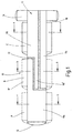
- the mechanical structure is a preferred one Embodiment of a high-current disconnector shown and designated 10.
- the circuit breaker comprises as he will only be called in the following should, a tubular contact carrier 11 with three mutually insulated contact areas 11a, 11b and 11c.
- the contact areas 11a, 11b and 11c are formed as sections of the tube shape and from each other for example by a suitable insulating layer 12 separated so that the entire contact carrier 11 has the tubular shape shown in FIG. 1.
- the contact area 11a is for the production of the electrical Connection to an external voltage source with a third-party base accessible from outside 13 connected (see FIG. 3), the contact area 11b forms a connection point 14 which is firmly connected to the battery 15 (Fig. 3), and the contact area 11c forms a contact connection 16, which is connected to the various lines that lead to the electrical system and form it.
- the mechanical displacement of the switching sleeve 17 by an external drive preferably an electric motor 18 or another motor, electromagnetic or hydraulic adjustment.
- Switching movements can both be automatically prompted if an undervoltage occurs, that is, by continuous Detecting the battery voltage and starting a disconnect position in the switch area, as well arbitrarily by an operator, namely the driver, given switching signal.
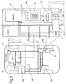
- a central control unit 18 is provided, the one Sensor 19 worked. 3 is for better Understanding still highly schematized the structure of a motor vehicle in an oval circuit with general consumers 20a, 20b, 20c, Generator 21, internal combustion engine 22 with starter 22a.
- the battery 15 is via a circuit breaker unit 23 connected to the various consumer feed lines, which, preferably in a uniform housing, the parts and components just explained has, in particular the high-current disconnector 10 with associated control electronics.
- the central control unit shown in FIG. 3 can 18 also other tasks in the area of Take over automotive electronics, for example the brain as a central electronic module, so to speak of the whole system and that of the invention underlying high-current switch as a sub-area manage his tasks. It is also possible, for this separate electronics, for example Microprocessor.
- the sensor system 19 has signal lines 19a, 19b, 19c, which monitor the battery voltage, for example operation, temperature and speed of the Determine internal combustion engine, or even Generator function capture to only some of the peripheral To name parameters that are necessary for the operation of the Disconnector must be included and observed.
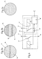
- Switching sleeve 17 In a first position the one that forms a contact bridge Switching sleeve 17 are both switches S1, S2 Fig. 4 opened - this corresponds to position A of the Disconnector 10 of FIG. 1, in which the Switching sleeve 17, which is indicated by dashed lines, only one with the jump start base or Foreign start connection 13 connected contact area 11a touched. Since no other contacts with each other are connected in this first position Battery and the jump start connector 13 from each other Cut. This position also separates the battery from all consumers. This position corresponds decommissioning the vehicle via a longer period of time and solves the problem of overseas transportation.
- the central control device 18th automatically moves into this second position, the the external start connection 13 with vehicle electrical system (and battery) connects if at this connection at all a positive voltage is detected because in this If the intention becomes recognizable, with the help of a External voltage supply, for example, a starting process initiate and / or charge the battery.
- a starting process initiate and / or charge the battery.
- the external start connection 13 dead i.e. during normal operation of a motor vehicle is the external start connection 13 dead.
- switch S2 In normal operation, which corresponds to the third position C. 1 means switch S2 always open, and switch S1 is closed, see above that in this switch position vehicle electrical system and battery are interconnected.
- This third switch position C of the high-current disconnector only, as mentioned earlier, in the case of a occurring on the battery 15 and undervoltage detected by the sensor system by disconnecting the battery from the vehicle electrical system or is based on manual input, for example by pressing a "transport switch” the input circuit 18a when a driver or another operator intends to Decommissioning the motor vehicle for a long time, for example in the event of overseas transport.
- the switching sleeve 17 according to Fig. 1 moves into position A, in this case de-energized jump start 13 a previous status check of the motor vehicle required which also through appropriate programming can be arranged.
- the central control unit therefore checks in particular the condition of the Internal combustion engine and in particular clarifies that Question whether the internal combustion engine just started because, in this case, at least with older ones Batteries can experience sharp voltage drops and mistakenly shutdown will, although the engine the next moment would have started.
- FIGS. 2a, 2b and 2c in the preferred embodiment that according to Fig. 2a, what the switching position C corresponds to the two contact areas "battery” and “electrical system” connected via the switching sleeve 17 are in the middle switch position B are all three contact areas 11a, 11b and 11c over the Switching sleeve 17 electrically connected and in position A according to Fig. 2c is only one Contact area available, that with the jump-start connection 13 and, since it is usually voltage-free, also the separation position between the electrical system and battery for the switching sleeve 17 forms.
Landscapes
- Engineering & Computer Science (AREA)
- Power Engineering (AREA)
- Electric Propulsion And Braking For Vehicles (AREA)
- Keying Circuit Devices (AREA)
Abstract
Description
DE 41 37 146 A1, DE 27 32 094 A1, DE 196 06 448 A1, US-PS 35 36 876, DE 34 02 372 A1, DE 42 11 578 C1, DE 33 03 185 A1, DE-AS 1 086 322, DE-GM G 92 16 774.8,
DE-GM G 91 15 293.3, DE 33 27 532 A1. Ferner sind trennbare Polverbinder bekannt aus US-PS 4 740 178 und DE 44 04 909 A1.
Die DE 196 06 448 A1 betrifft eine Anordnung, die bei einem Unfall die Verbindung zwischen Batterie und dem Bereich Starter/Generator mittels einer Treibladung auftrennt. Die Treibladung wird durch ein Signal des Airbag-Sensors ausgelöst. Die Trennung ist dauerhaft, so daß ein erneuter Start des Fahrzeugs nicht mehr möglich ist. Zur Reparatur müssen mindestens Teile des Starterkabels ausgetauscht werden.
Claims (9)
- Schalter für Fahrzeuge, insbesondere Hochstrom-Trennschalter zwischen einer Batterie und einem Verbrauchernetz bei Kraftfahrzeugen, gekennzeichnet durch einen, einen Fremdstartanschluß (13) umfassenden mehrstufigen Schalter (10; S1, S2), dessen weitere Kontaktstellen mindestens einen Batterieanschluß (14) und einen Bordnetzanschluß (16) bilden.
- Schalter nach Anspruch 1, dadurch gekennzeichnet, daß mindestens drei voneinander isolierte Kontaktgebiete (11a, 11b, 11c) vorgesehen sind und ein bewegliches, in mindestens drei verschiedene Kontaktpositionen (A, B, C) zu den Kontaktgebieten bewegbares, eine Brückenfunktion ausübendes Kontaktglied, wobei ein erstes Kontaktgebiet (11b) mit dem Batterieanschluß (14), ein zweites (11c) mit dem Bordnetzanschluß (16) und ein drittes Kontaktgebiet (11a) mit dem Fremdstartanschluß (13) verbunden ist.
- Schalter nach Anspruch 1 oder 2, dadurch gekennzeichnet, daß ein rohrförmiger, die sich in axialer Richtung erstreckenden gegeneinander isolierten und sich axial überlappenden Kontaktgebiete (11a, 11b, 11c) bildender Kontaktträger (11) vorgesehen ist, auf dem eine eine Kontaktbrücke bildende und die Kontaktbereiche (11a, 11b, 11c) je nach eigener Position elektrisch miteinander verbindende Schalthülse (17) in axialer Richtung verschiebbar gelagert ist.
- Schalter nach einem der Ansprüche 1 bis 3, dadurch gekennzeichnet, daß zur Verschiebung der Schalthülse (17) in die verschiedenen Kontaktpositionen (A, B, C) elektromotorische, hydraulische und/oder elektromagnetische Stellglieder vorgesehen sind.
- Schalter nach einem der Ansprüche 1 bis 4, dadurch gekennzeichnet, daß ein Steuergerät (18; elektronische Steuereinheit 18') vorgesehen ist, das das Stellglied (18b) für die Verschiebung der Schalthülse (17) ansteuert und mit einer Sensorik (19) allgemeine Parameter, Betriebs- und Schaltzustände des Kraftfahrzeugs, die Batteriespannung (15) und die Spannung des Fremdstartanschlusses (13) überwacht.
- Schalter nach Anspruch 5, dadurch gekennzeichnet, daß dem Steuergerät (18; elektronische Steuereinheit 18') eine manuell betätigbare Eingabeschaltung (18a) zugeordnet ist.
- Schalter nach einem der Ansprüche 1 bis 6, dadurch gekennzeichnet, daß die Schalthülse (17) Mittel zur manuellmechanischen Verstellung aufweist.
- Schalter nach einem der Ansprüche 1 bis 7, dadurch gekennzeichnet, daß das Kontaktglied (Schalthülse 17) in der dritten Stellung (Normalposition C) die Batterie (15) mit dem Bordnetz und in der zweiten Stellung (Fremdstartposition B) den Fremdstartanschluß (13) mindestens mit dem Bordnetz und in der ersten Stellung (Trennposition A) zum Batterie- und Bordnetzanschluß (14, 16) kontaktfrei gehalten ist.
- Schalter nach einem der Ansprüche 1 bis 8, dadurch gekennzeichnet, daß das Steuergerät (18; elektronische Steuereinheit 18') so ausgebildet ist, daß mindestens die Höhe der Eigenbatteriespannung, die Polarität am Fremdstartanschluß (13) sowie der Betriebszustand des Fahrzeugs überwacht undbei Unterspannung die Batterie (15) vom Bordnetz getrennt wird;der Fremdstartanschluß (13)nur dann angefahren wird, wenn die Polarität der ihr zugeführten Hilfsepannung korrekt ist unddurch Schaltsignale einer Bedienungsperson die Batterie (15) dann vom Bordnetz getrennt oder mit ihm verbunden wird, wenn die sonstigen Betriebsparameter des Fahrzeugs diesen Trennvorgang zulassen.
Applications Claiming Priority (2)
| Application Number | Priority Date | Filing Date | Title |
|---|---|---|---|
| DE19922330 | 1999-05-14 | ||
| DE19922330A DE19922330C1 (de) | 1999-05-14 | 1999-05-14 | Schalter für Fahrzeuge |
Publications (3)
| Publication Number | Publication Date |
|---|---|
| EP1052662A2 true EP1052662A2 (de) | 2000-11-15 |
| EP1052662A3 EP1052662A3 (de) | 2002-04-03 |
| EP1052662B1 EP1052662B1 (de) | 2003-10-01 |
Family
ID=7908123
Family Applications (1)
| Application Number | Title | Priority Date | Filing Date |
|---|---|---|---|
| EP00109368A Expired - Lifetime EP1052662B1 (de) | 1999-05-14 | 2000-05-02 | Schalter für Fahrzeuge |
Country Status (2)
| Country | Link |
|---|---|
| EP (1) | EP1052662B1 (de) |
| DE (2) | DE19922330C1 (de) |
Cited By (3)
| Publication number | Priority date | Publication date | Assignee | Title |
|---|---|---|---|---|
| WO2001094777A1 (de) * | 2000-06-09 | 2001-12-13 | Robert Bosch Gmbh | Startvorrichtung |
| DE10120298A1 (de) * | 2001-04-25 | 2002-11-07 | Delphi Tech Inc | Elektrischer Schalter |
| EP2325972A3 (de) * | 2009-10-20 | 2012-10-24 | Hoppecke Advanced Battery Technology GmbH | Vorrichtung zum Betreiben einer Akkumulatoreinheit |
Families Citing this family (6)
| Publication number | Priority date | Publication date | Assignee | Title |
|---|---|---|---|---|
| DE10047791A1 (de) * | 2000-09-18 | 2002-03-28 | Volkswagen Ag | Verpolschutz für Fremdstartpol |
| DE10155003B4 (de) * | 2000-11-13 | 2014-01-16 | Volkswagen Ag | Vorrichtung zur Vermeidung der Tiefentladung einer Batterie in einem Kraftfahrzeug-Bordnetz |
| DE102006015502B4 (de) * | 2006-03-13 | 2008-06-19 | Visteon Global Technologies Inc., Van Buren | Gestufte Drehzahlverstellung für einen Niederspannungselektromotor |
| DE102008063652A1 (de) | 2008-12-18 | 2010-06-24 | Daimler Ag | Elektrisches Bordnetz für ein Fahrzeug |
| DE102011003564A1 (de) | 2011-02-03 | 2012-08-09 | Bayerische Motoren Werke Aktiengesellschaft | Kraftfahrzeug mit einer Fremdstartvorrichtung |
| DE102013215704A1 (de) * | 2013-08-08 | 2015-02-12 | Robert Bosch Gmbh | Batteriesystem mit einer Batterie-Trenneinheit und einer Batterie-Steuereinheit |
Family Cites Families (24)
| Publication number | Priority date | Publication date | Assignee | Title |
|---|---|---|---|---|
| NL89128C (de) * | 1956-02-15 | 1958-09-15 | ||
| US3536876A (en) * | 1967-12-06 | 1970-10-27 | William R Lastinger | Quick disconnect battery apparatus |
| DE2732094A1 (de) * | 1977-07-15 | 1979-01-18 | Didier Werke Ag | Schiebeverschluss fuer metallschmelze enthaltende gefaesse |
| DE2836041A1 (de) * | 1978-08-17 | 1980-02-28 | Bosch Gmbh Robert | Verpolschutzanordnung |
| DE2919022A1 (de) * | 1979-05-11 | 1980-11-20 | Bosch Gmbh Robert | Verpolschutzanordnung fuer ein batterieladesystem |
| DE2919021A1 (de) * | 1979-05-11 | 1980-11-20 | Bosch Gmbh Robert | Verpolschutzanordnung fuer ein batterieladesystem |
| SE426192B (sv) * | 1982-02-04 | 1982-12-13 | Dafo Brand Ab | Anordning vid batterifranskiljare |
| DE3327532A1 (de) * | 1983-07-30 | 1985-02-07 | Iveco Magirus AG, 7900 Ulm | Trennschalteinrichtung fuer kraftfahrzeuge |
| DE3402372A1 (de) * | 1984-01-25 | 1985-08-01 | Doduco KG Dr. Eugen Dürrwächter, 7530 Pforzheim | Elektrisches schaltelement |
| EP0305610A1 (de) * | 1987-09-01 | 1989-03-08 | Vbh Investments (Proprietary) Limited | Verbindungsvorrichtung für eine Batterieklemme |
| DE3827045A1 (de) * | 1988-08-10 | 1990-02-22 | Ullmann Ulo Werk | Verpolungsschutzeinrichtung fuer akkuladegeraete |
| DE4040405A1 (de) * | 1990-12-17 | 1992-07-02 | Daimler Benz Ag | Entladeschutzschaltung fuer einen durch verbraucher belastbaren stromspeicher eines kraftfahrzeugs |
| DE4110240C1 (en) * | 1991-03-28 | 1992-10-08 | Mercedes-Benz Aktiengesellschaft, 7000 Stuttgart, De | Vehicle current path protection device - separates battery from load upon occurrence of electrical fault |
| DE4137146A1 (de) * | 1991-11-12 | 1993-05-13 | Kern Johann Dipl Ing | Verfahren zur verhinderung der unabsichtlichen entladung des akkumulators einer transportvorrichtung, z.b. eines kfz und vorrichtung nach diesem verfahren |
| DE9216774U1 (de) * | 1991-12-10 | 1993-05-27 | Bouchier, France | Fernbedientes Batterieschloß |
| DE9115293U1 (de) * | 1991-12-10 | 1992-02-20 | Bouchier, France, Parcent, Alicante | Batterieschloß |
| DE4211578C1 (en) * | 1992-04-07 | 1993-04-29 | Mercedes-Benz Aktiengesellschaft, 7000 Stuttgart, De | Vehicle battery isolating circuit - has switch to isolate battery from generator, operable from engine compartment, and second switch near driver seat to remotely actuate first |
| DE4231970C2 (de) * | 1992-09-24 | 1995-02-16 | Bsg Schalttechnik | Batterieladegerät |
| DE9212878U1 (de) * | 1992-09-24 | 1992-11-05 | BSG-Schalttechnik GmbH & Co KG, 7460 Balingen | Batterieladegerät |
| JP2815081B2 (ja) * | 1993-02-18 | 1998-10-27 | 矢崎総業株式会社 | バッテリ間接続用コネクタ装置 |
| US5612659A (en) * | 1994-08-08 | 1997-03-18 | Quicksilver Engineering | Battery protecting circuit breaker |
| DE19603117A1 (de) * | 1995-02-17 | 1996-08-29 | Int Rectifier Corp | Verpolungs-Schutzschaltung |
| DE19606448A1 (de) * | 1996-02-21 | 1997-08-28 | Bayerische Motoren Werke Ag | Batterie-Kabelklemme für Fahrzeuge |
| AU7941998A (en) * | 1997-05-28 | 1998-12-30 | Euston Holdings Limited | Battery and battery controller |
-
1999
- 1999-05-14 DE DE19922330A patent/DE19922330C1/de not_active Expired - Fee Related
-
2000
- 2000-05-02 EP EP00109368A patent/EP1052662B1/de not_active Expired - Lifetime
- 2000-05-02 DE DE50003876T patent/DE50003876D1/de not_active Expired - Lifetime
Cited By (3)
| Publication number | Priority date | Publication date | Assignee | Title |
|---|---|---|---|---|
| WO2001094777A1 (de) * | 2000-06-09 | 2001-12-13 | Robert Bosch Gmbh | Startvorrichtung |
| DE10120298A1 (de) * | 2001-04-25 | 2002-11-07 | Delphi Tech Inc | Elektrischer Schalter |
| EP2325972A3 (de) * | 2009-10-20 | 2012-10-24 | Hoppecke Advanced Battery Technology GmbH | Vorrichtung zum Betreiben einer Akkumulatoreinheit |
Also Published As
| Publication number | Publication date |
|---|---|
| EP1052662A3 (de) | 2002-04-03 |
| EP1052662B1 (de) | 2003-10-01 |
| DE50003876D1 (de) | 2003-11-06 |
| DE19922330C1 (de) | 2000-12-21 |
Similar Documents
| Publication | Publication Date | Title |
|---|---|---|
| DE19922331C1 (de) | Verfahren zum Betrieb einer Sicherheitseinrichtung für Kraftfahrzeuge | |
| EP1144224B1 (de) | Batteriebordnetz mit sicherheitsabschaltung | |
| EP2017935B1 (de) | Elektronischer Trennschalter | |
| EP1232073B1 (de) | Zwei-batteriensystem | |
| EP3022432B1 (de) | Elektronische sicherheitsabschaltung für kraftfahrzeuge | |
| DE102012015523B4 (de) | Hochvoltbatterie mit Entlademöglichkeit nach einem Crash | |
| EP1386389A1 (de) | Vorrichtung zur energieeinspeisung in ein mehrspannungsbordnetz eines kraftfahrzeugs | |
| EP3571087B1 (de) | Batteriesystem für ein fahrzeug | |
| DE102007026164A1 (de) | Elektrisches Versorgungssystem für ein Kraftfahrzeug | |
| DE102011003564A1 (de) | Kraftfahrzeug mit einer Fremdstartvorrichtung | |
| DE102017112701B4 (de) | Elektrische Hochspannungssysteme und Trennvorrichtungen | |
| DE102013017409A1 (de) | Batteriesystem mit einer Hochvolt-Batterie und einem Batterie-Management-System, insbesondere für ein elektromotorisch antreibbares Fahrzeug | |
| WO2014191135A1 (de) | Modultrennung in batteriesystemen bei unfällen | |
| EP1052662B1 (de) | Schalter für Fahrzeuge | |
| DE102010030732B4 (de) | Vorrichtung zur Steuerung des elektrischen Ladevorgangs eines Energiespeichers eines Fahrzeugs | |
| DE10361743A1 (de) | Vorrichtung zur Umschaltung einer Batterie | |
| DE19929246C2 (de) | Batteriesystem | |
| DE102012024738A1 (de) | Energiespeichervorrichtung und Fahrzeug | |
| DE102021109345A1 (de) | Trennschaltung zur reversiblen galvanischen Trennung eines Verbrauchers von einer Gleichspannungsquelle | |
| DE102015008005B4 (de) | Notlaufbetrieb für ein Kraftfahrzeug mit zwei Bordnetzen | |
| DE19922332C1 (de) | Sicherheitseinrichtung für Fahrzeuge | |
| EP2892751B1 (de) | Batterieanordnung zum betrieb elektrischer verbraucher in einem fahrzeug zur gefahrgutbeförderung | |
| EP1306927B1 (de) | Elektrischer Akkumulator | |
| DE102020120410B3 (de) | Verfahren zum Betreiben eines Bordnetzes, Bordnetz sowie Kraftfahrzeug mit einem Bordnetz | |
| DE19937491B4 (de) | Sicherheitseinrichtung für das Bordnetz eines Fahrzeugs |
Legal Events
| Date | Code | Title | Description |
|---|---|---|---|
| PUAI | Public reference made under article 153(3) epc to a published international application that has entered the european phase |
Free format text: ORIGINAL CODE: 0009012 |
|
| AK | Designated contracting states |
Kind code of ref document: A2 Designated state(s): DE ES FR GB IT Kind code of ref document: A2 Designated state(s): AT BE CH CY DE DK ES FI FR GB GR IE IT LI LU MC NL PT SE |
|
| AX | Request for extension of the european patent |
Free format text: AL;LT;LV;MK;RO;SI |
|
| PUAL | Search report despatched |
Free format text: ORIGINAL CODE: 0009013 |
|
| AK | Designated contracting states |
Kind code of ref document: A3 Designated state(s): AT BE CH CY DE DK ES FI FR GB GR IE IT LI LU MC NL PT SE |
|
| AX | Request for extension of the european patent |
Free format text: AL;LT;LV;MK;RO;SI |
|
| 17P | Request for examination filed |
Effective date: 20020515 |
|
| AKX | Designation fees paid |
Free format text: DE ES FR GB IT |
|
| 17Q | First examination report despatched |
Effective date: 20021204 |
|
| GRAH | Despatch of communication of intention to grant a patent |
Free format text: ORIGINAL CODE: EPIDOS IGRA |
|
| RIN1 | Information on inventor provided before grant (corrected) |
Inventor name: DR. RER. NAT. BLESSING, ALF Inventor name: LOEWEL, ANDREAS, DIPL.-ING. Inventor name: ALKSNAT, HOLGER Inventor name: ROHDE, WOLFGANG Inventor name: SCHULZ, THOMAS, DIPL.-ING. Inventor name: DINGER, JUERGEN Inventor name: SEYER, RHEINHARD, DIPL.-ING. |
|
| GRAS | Grant fee paid |
Free format text: ORIGINAL CODE: EPIDOSNIGR3 |
|
| GRAA | (expected) grant |
Free format text: ORIGINAL CODE: 0009210 |
|
| AK | Designated contracting states |
Kind code of ref document: B1 Designated state(s): DE ES FR GB IT |
|
| PG25 | Lapsed in a contracting state [announced via postgrant information from national office to epo] |
Ref country code: GB Free format text: LAPSE BECAUSE OF FAILURE TO SUBMIT A TRANSLATION OF THE DESCRIPTION OR TO PAY THE FEE WITHIN THE PRESCRIBED TIME-LIMIT Effective date: 20031001 |
|
| REG | Reference to a national code |
Ref country code: GB Ref legal event code: FG4D Free format text: NOT ENGLISH |
|
| REG | Reference to a national code |
Ref country code: IE Ref legal event code: FG4D Free format text: GERMAN |
|
| REF | Corresponds to: |
Ref document number: 50003876 Country of ref document: DE Date of ref document: 20031106 Kind code of ref document: P |
|
| PG25 | Lapsed in a contracting state [announced via postgrant information from national office to epo] |
Ref country code: ES Free format text: LAPSE BECAUSE OF FAILURE TO SUBMIT A TRANSLATION OF THE DESCRIPTION OR TO PAY THE FEE WITHIN THE PRESCRIBED TIME-LIMIT Effective date: 20040112 |
|
| GBV | Gb: ep patent (uk) treated as always having been void in accordance with gb section 77(7)/1977 [no translation filed] |
Effective date: 20031001 |
|
| ET | Fr: translation filed | ||
| REG | Reference to a national code |
Ref country code: IE Ref legal event code: FD4D |
|
| PLBE | No opposition filed within time limit |
Free format text: ORIGINAL CODE: 0009261 |
|
| STAA | Information on the status of an ep patent application or granted ep patent |
Free format text: STATUS: NO OPPOSITION FILED WITHIN TIME LIMIT |
|
| 26N | No opposition filed |
Effective date: 20040702 |
|
| PGFP | Annual fee paid to national office [announced via postgrant information from national office to epo] |
Ref country code: FR Payment date: 20100525 Year of fee payment: 11 |
|
| PGFP | Annual fee paid to national office [announced via postgrant information from national office to epo] |
Ref country code: DE Payment date: 20100430 Year of fee payment: 11 Ref country code: IT Payment date: 20100515 Year of fee payment: 11 |
|
| REG | Reference to a national code |
Ref country code: DE Ref legal event code: R119 Ref document number: 50003876 Country of ref document: DE |
|
| REG | Reference to a national code |
Ref country code: DE Ref legal event code: R119 Ref document number: 50003876 Country of ref document: DE |
|
| REG | Reference to a national code |
Ref country code: FR Ref legal event code: ST Effective date: 20120131 |
|
| PG25 | Lapsed in a contracting state [announced via postgrant information from national office to epo] |
Ref country code: IT Free format text: LAPSE BECAUSE OF NON-PAYMENT OF DUE FEES Effective date: 20110502 |
|
| PG25 | Lapsed in a contracting state [announced via postgrant information from national office to epo] |
Ref country code: FR Free format text: LAPSE BECAUSE OF NON-PAYMENT OF DUE FEES Effective date: 20110531 |
|
| PG25 | Lapsed in a contracting state [announced via postgrant information from national office to epo] |
Ref country code: DE Free format text: LAPSE BECAUSE OF NON-PAYMENT OF DUE FEES Effective date: 20111130 |