EP1052471B1 - Munition explosive à éclats contrôlés formés par explosif - Google Patents
Munition explosive à éclats contrôlés formés par explosif Download PDFInfo
- Publication number
- EP1052471B1 EP1052471B1 EP20000401293 EP00401293A EP1052471B1 EP 1052471 B1 EP1052471 B1 EP 1052471B1 EP 20000401293 EP20000401293 EP 20000401293 EP 00401293 A EP00401293 A EP 00401293A EP 1052471 B1 EP1052471 B1 EP 1052471B1
- Authority
- EP
- European Patent Office
- Prior art keywords
- explosive
- wall
- round according
- dimples
- round
- Prior art date
- Legal status (The legal status is an assumption and is not a legal conclusion. Google has not performed a legal analysis and makes no representation as to the accuracy of the status listed.)
- Expired - Lifetime
Links
Images

Classifications
-
- F—MECHANICAL ENGINEERING; LIGHTING; HEATING; WEAPONS; BLASTING
- F42—AMMUNITION; BLASTING
- F42B—EXPLOSIVE CHARGES, e.g. FOR BLASTING, FIREWORKS, AMMUNITION
- F42B12/00—Projectiles, missiles or mines characterised by the warhead, the intended effect, or the material
- F42B12/02—Projectiles, missiles or mines characterised by the warhead, the intended effect, or the material characterised by the warhead or the intended effect
- F42B12/20—Projectiles, missiles or mines characterised by the warhead, the intended effect, or the material characterised by the warhead or the intended effect of high-explosive type
- F42B12/22—Projectiles, missiles or mines characterised by the warhead, the intended effect, or the material characterised by the warhead or the intended effect of high-explosive type with fragmentation-hull construction
Definitions
- the invention relates to explosive ammunition generating bursts.
- bursts such as hand grenades, of the offensive or defensive type, or again for example rifle grenades.
- These munitions typically include an explosive charge, a head of ignition, and a casing generating fragments, which is generally metallic and which surrounds at least part of the explosive charge.
- the firing head is usually part of a set called an igniter or initiator plug which is intended to trigger the explosion of the ammunition a few seconds after that a pin has been removed from this plug.
- explosive ordnance have been proposed, including explosive charges of various powers. Around the explosive charge, we proposed to place different walls, such as pre-fragmented metal shells or plastic envelopes in which are drowned out of preformed flakes of various geometries, such as for example metal balls.
- Known explosive ordnance is generally aimed at obtaining a high efficiency in the target.
- the proposed ammunition thus aims generally to propel shards in large numbers and with great kinetic energy.
- a hand grenade comprising two shine-generating layers surrounding a charge main, each with conical or shaped contours fingerprints (for example of points) of low mass.
- the different grenade with multiple metallic layers allow certainly to achieve a high density of projectiles in an area surrounding the explosion point, but they do not control the radius of the grenade. For most of them, high energy are found at very high rays, which is dangerous for the user.
- Such a grenade therefore does not provide both efficiency suitable at short distance and a harmless effect beyond a distance of security of about thirty meters.
- the grenade proposed in FR 2 536 164 certainly with imprints entering the explosive, makes use of these imprints for cut out the external chip-generating wall.
- the division remains random and does not allow a control of the behavior of the flakes.
- the main purpose of the present invention is to provide ammunition explosive does not have these various drawbacks, that is to say a ammunition which allows both to guarantee a high efficiency in the target within a given first radius, and both guarantee security, therefore the absence of projection of shards at high speed, beyond a second given radius which is greater than the first.
- an explosive munition at explosive shrapnel comprising a firing head, a charge explosive, a part generating fragments, and a wall in contact with the explosive which includes a set of concave caps extending towards the inside of the munition, characterized in that each of these fingerprints presents a geometry adapted to constitute with the explosive charge at its contact a charge formed of the hollow charge or generating charge type nucleus, and in that the splinter-generating part is formed by a single wall, which is that which is in contact with the explosive.
- the concave caps constituting imprints are in the form of cones with rounded tip or similar spherical caps.
- Figure 1 shows a hand grenade body, comprising a casing generating fragments formed by explosive 7 and an explosive charge 4.
- This grenade body also has a cavity adapted to receive a detonator or an igniter plug.
- the igniter plug has not been shown in FIG. 1. according to the invention use any type of conventional igniter plug, suitable for initiate a charge of 90g of explosive substance such as tolite.
- a classic initiator comprising a charge of 1.6 to 2 grams of pentrite for example will be perfectly suited to initiate the grenade body which will be described below.
- the pomegranate body of Figure 1 has a general shape ovoid slightly elongated along a vertical axis X.
- the grenade body has two opposite ends forming each a plate perpendicular to the X axis.
- a lower plate forms a base for placing the grenade in an upright position, and a tray upper is suitable for fixing the igniter plug.
- the upper plate is thus provided in its center with a threaded orifice 3 constituting the entry of the cavity previously mentioned, adapted to receive part of the igniter plug inside the body of the grenade.
- This cavity forms a passage which extends into the grenade parallel to the X axis, over a length substantially three-quarters equal the height of the grenade.
- the pomegranate body is made up of three main elements, which are a protective and protective envelope 1 made of plastic, a metal casing 7 generating shards, and an explosive charge 4.
- the casing 1 surrounds the entire body of the grenade. She is consisting here of acrylonitrile butadiene styrene known under the name ABS. It advantageously has a thickness of between 2 and 3.4 mm.
- the plastic envelope 1 is made up of three parts: a half-shell upper 9, a lower half-shell 10, and a plug 2.
- a first part 9 substantially forms a hemispherical wall, constituting an upper half-shell of the envelope 1.
- the wall forming this hemisphere has at its center the orifice 3 forming an inlet of the receiving passage of the igniter plug.
- On orifice 3 thus opens a cylindrical sleeve 6 molded with the hemisphere 9, and extending inside the hemisphere 9, constituting the receiving passage of the igniter plug.
- This cylindrical sleeve 6 has the same axis of revolution X as the hemisphere 9.
- This first half-shell 9 is fixed to a second half-shell 10 also having a central orifice 8.
- a plastic plug 2 forming the lower base of the pomegranate body.
- the plug 2 has a concave upper face 5 suitable for internally extend the second half-shell 10 continuously.
- the grenade therefore has an inner surface which is ovoid and continuous, showing no detachment except in contact with the sleeve 6.
- This concave and oval interior surface is, in accordance with the invention, covered internally with the grenade body by a metal casing 7 generating shards.
- the metal envelope 7 therefore forms an ovoid wall which surrounds almost entirely an interior space of the grenade body.
- the envelope metallic 7 therefore has the shape of an eggshell in which made an upper opening.
- This upper opening is crossed by the sleeve 6, and has a periphery which is complementary to the contour of the sleeve 6.
- the metal casing 7 is consisting of two parts joined together so as to form a continuous surface. A first of these two parts completely covers the concave upper surface of the plug 2, and is limited to this surface.
- a second part covers the rest of the interior ovoid surface of the plastic envelope 1, i.e. the oval interior surface materialized by the lower and upper half-shells.
- the envelope 7 is, according to one embodiment of the invention, fixed by fitting inside the plastic casing 1.
- the wall covering the plug 2 is integral with this same plug, so that when the plug is removed from the rest of the plastic body 1, the wall metal covering this cap is also removed. Pomegranate body can thus be filled with explosive substance through the lower orifice which is thus discovered.
- the envelope 7 comprises two half-shells complementary to the interior of each of the two half-shells of the plastic envelope 1.
- This arrangement allows easy assembly of the body pomegranate. Indeed, each half-shell of the plastic envelope is in first covered internally by one of the two half-shells metallic, so that two metal / plastic half-shells are obtained. These two metal / plastic half-shells are then assembled edge to edge.
- the wall 7 is formed of a multitude of small cavities or indentations formed by the metal wall 7. These cavities each have a concave shape opposite with inside the grenade. More specifically, according to Figure 1, these forms concaves consist of a cone whose top is directed inward pomegranate.
- the wall 7 presents at all points, whether at a vertex or at the base of an imprint, a constant thickness.
- Each cone or imprint has a classically defined base as being a contour line belonging to the cone and whose diameter or the width is maximum, this width being measured tangentially to envelope 7.
- Each cone or imprint is, by the contour formed by its base, rigidly attached to the cones or imprints adjacent to it.
- the only separation within the wall 7 corresponds to a circular separation between the wall covering the plug 2 and the wall covering the rest of the inner surface of the body plastic 1.
- these two walls of the envelope 7 can be produced under their final shape directly during molding, or else be shaped by stamping.
- the wall 7 forms approximately 800 cones or imprints pointing towards the interior of the grenade.
- the grenade is filled with an explosive substance in a space which is delimited on the one hand by the metallic envelope 7 and on the other hand by the sleeve outline 6.
- the explosive substance is in direct contact with the metal casing 7 so that the casing 7 is taken in sandwich between this explosive substance 4 and the plastic envelope 1.
- the role of the plastic envelope is not only to to guarantee the watertightness of the grenade body, but also, by its rigidity, to produce mechanical maintenance of the metal casing 7, maintenance of the igniter plug inside the metallic casing 7, and a protection of the metal casing 7 against shocks.
- the shock wave therefore approaches the metal envelope in a direction propagation perpendicular to it, so that the front of the wave of shock extends parallel to the local metal wall.
- the inventors have discovered that for particular dimensions of the concave caps 11 delimiting the explosive charge, we obtain at each shell a load / shell combination forming a mini load formed, of hollow charge type or preferably of charge type nucleus generator.
- This microprojectile is particularly effective at short distances.
- this microprojectile is propelled in a precise direction, defined by the main direction of the cap 11, so that the direction microprojectile is therefore perfectly under control.
- the microprojectile of charge formed does not produce an effect. undesirable beyond a chosen safety distance.
- the energy released by the charge formed essentially resides in the very high speed of the microprojectile, and little in the mass inertia of the microprojectile, which is very weak. Therefore, this energy dissipates very quickly during distance to the point of explosion, unlike grenades known which release the energy produced essentially by the propulsion heavy flakes at low speeds compared to those obtained here with a charge effect formed.
- the explosive fragments generated by the prior art grenades by inertia keep a high kinetic energy on very long distances, while the fragments formed by explosives generated here are very light and very fast, so their kinetic energy very high at the start by the effect of charge formed decreases very quickly in because of their low mass.
- the most useful part of the explosive for training and microprojectile propulsion is that which surrounds the cone.
- the central part explosive can thus be modified without inducing a net modification of the behavior of the ammunition, subject to modifying neither the form of the detonation wave significantly nor the capacity of the explosive device to transmit the detonation wave to areas surrounding the footprints 11.
- the imprints 11 When subjected to the shock wave, the imprints 11 are separate from each other and therefore each behaves like a independent impact.
- the mass of the projectiles is therefore perfectly predetermined and their controlled kinetics.
- the inventors were also able to discover that by precisely adapting certain dimensional parameters defining the geometry of the cones or footprints, the projectiles resulting from these cones or footprints do not produce no more efficiency in the target beyond a chosen radius around the point explosion, while having significant efficiency at a short distance from the point explosion.
- the angular opening i.e. the angle measured between two generating the imprint, is referenced ⁇ in Figure 2.
- the width of the footprint base, measured tangentially to a average surface of the envelope 7, is referenced L.
- the thickness of the conical wall is referenced E.
- the imprints are made of copper and are formed with a wall thickness between 0.5 and 0.8 mm.
- the imprints can be replaced keeping the charge effect formed by pyramids or more generally by concave wall portions each forming a footprint with the apex directed towards the interior of the grenade.
- a concave wall forming a cap As in the case of a cone, a distinction is made on a concave wall forming a cap, a wall thickness E, an angular opening ⁇ , and a base width L.
- the inventors have found that the parameters ⁇ and L can be adapted to ensure that explosive shards are not more effective beyond 25 m.
- the inventors have been able to observe that at equal values of ⁇ , L and E, the efficiency at 5m and the safety radius are of the same order for footprints and pyramids, but with an increase in efficiency in target with pyramids.
- the fragments formed by explosive or impacts have a very high initial velocity and suffer a high loss of energy during their trajectory, so the efficiency of the grenade is particularly high at 5 m and almost non-existent beyond a radius 25 m.
- the constituent material of wall 7 is standard annealed copper.
- the invention is not not limited to a flake wall formed by copper explosive. Any wall in one material of density and ductility close to that of copper can be adopted with dimensions close to those mentioned above so as to obtain the combination of results described above.
- the invention thus provides for replacing copper with aluminum.
- Aluminum has the advantage of being cheaper than copper, but it is lighter, which has the effect of reducing the range of shards.
- the base feeder L is 3 mm
- the angular opening ⁇ is 120 degrees
- the wall thickness E is 0.5 mm.
- Such an imprint has a height or depth of approximately 1mm.
- the inventors have discovered that by increasing the width L, we gets more energetic explosive shards with a longer range high, but a density of microprojectiles and associated nuclei which is lower in the sheaf because the number of fragments formed by explosive is itself weaker.
- a diameter or a width of imprint L equal to 3 mm corresponds to a number of imprints substantially equal to 800 over the entire grenade and to 13 cones per cm 2 of metallic envelope.
- a value of L of 4 mm corresponds to a number of imprints of approximately 550 and to 7 imprints per cm 2 .
- a diameter L of approximately 5 mm corresponds to a number of imprints of approximately 350 and to 5 imprints per cm 2 .
- the inventors have also discovered that the greater the angular opening a is closed, and the more energetic the microprojectile / nucleus combination. Of more, a more closed angular opening has the effect of reducing the range effective burst of explosives.
- the plastic envelope under the effect of the explosion, does not generate any shine likely to influence the efficiency in the target. It only has a maintenance effect general of the grenade structure and impact protection.
- this second wall 1 is chosen sufficiently flexible so as not to attenuate the energy released by the charges formed and firm enough to protect the splinter-generating wall 7 against ammunition transport shocks.
- a explosive charge consisting of 90 grams of poured hexolite consisting of 60% hexogen and 40% tolite.
- the hexolite used here is poured, we may also use a compressed explosive charge.
- Hexocire is a mixture of 98% Hexogen and 2% wax promoting compression.
- Tolite D is a type of tolite with a melting temperature of particularly high, which is one of the purest tolites.
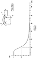
- FIG. 3 shows a plot representing the effectiveness of the sheaf of fragments formed by explosive generated as a function of the distance separating the grenade's explosion point and target, in the case of the grenade Figures 1 and 2.
- This PMHC parameter is conventionally calculated from a number of perforations found in a fixed surface aluminum target placed at a distance d from the point of explosion, and facing the point of explosion.
- the target is more precisely formed of three aluminum sheets each having a surface of 0.476 m 2 and placed one against the other. These three sheets have thicknesses of 1.5 mm, 1.0 mm and 1.5 mm respectively, and are placed so that the sheet of thickness 1.0 mm is sandwiched between the two sheets d 1.5 mm thick with a test space between the sheets 1 cm thick.
- the target is placed at distance d from the ammunition. After explosion, the number of perforations in each of the three sheets is counted.
- N1 being the density of flakes having passed through a single sheet
- N2 being the density of flakes having passed through two sheets
- N3 being the density of flakes having passed through three sheets.
- a strictly zero PMHC value at a given distance corresponds to the fact that no splinter pierces any of the aluminum sheets to this distance.
- a value of PMHC 0.5 at this distance is satisfactory, and in particular a PMHC greater than 0.4 to 5 meters.
- the plot in Figure 3 shows that the grenade in Figures 1 and 2 is satisfactory in a radius between 0 and 6 meters, and that no burst of high energy is more present beyond 25 meters.
- a grenade conforming to the invention generates a sheaf of splinters formed by explosive distribution particularly uniform angle around the point of explosion.
- the grenade according to the invention makes it possible to obtain maximum efficiency at a few meters from the point of explosion, unlike the case of splinters classics, such as balls, with which the maximum energy is reached from the start of the flakes, the speed of the flake formed by explosive typically decreasing hyperbolically as a function of distance.
- the inventors have found that the microprojectile or the dart separated from the rest of the metal wall 7 in the case of this invention is destabilized at a distance between 2 and 8 meters from the point of explosion, and separates into pieces after reaching its distance maximum efficiency.
- the number of shards formed by explosive is rapidly multiplied over the course of these, compared to their theoretical number, which has the effect of keeping efficiency at a level raised over a distance greater than 5 meters.
- the low mass of the luster formed by theoretical explosive i.e. the imprint 11 shown in Figure 2, the reduction of this imprint which still divides the mass of the individual fragments, and the large speed of the bursts, are three characteristics which induce a fall of energy considerable of the luster formed by individual explosive beyond about 8 meters.
- the low mass of the explosive fragments makes the particularly light pomegranate. It therefore has the advantage of being able to be launched with great precision.
- the geometric parameters ⁇ (or P), E and L can be modified by any facility without resizing other constituent parts of the grenade as the wall 7.
- the grenade according to the invention is therefore particularly adaptable to various specifications.
- the invention is not limited to the sole field of hand grenades, the arrangements described above may be adapted by a person skilled in the art to any type of explosive ammunition such as a rifle grenade for example.
- the cap 11 illustrated in FIG. 2bis annexed has the form of a concave spherical shell concave towards the inside of the ammunition.
- this cap 11 in the form of imitation spherical cap has a base width L of the order of 3 mm, a depth P of the order of 1.2 mm and a wall thickness E of the order of 0.6 mm.
Landscapes
- Engineering & Computer Science (AREA)
- Chemical & Material Sciences (AREA)
- Combustion & Propulsion (AREA)
- General Engineering & Computer Science (AREA)
- Aiming, Guidance, Guns With A Light Source, Armor, Camouflage, And Targets (AREA)
- Portable Nailing Machines And Staplers (AREA)
Description
- la figure 1 est une vue en coupe longitudinale d'un corps de grenade à main conforme à la présente invention ;
- la figure 2 est une vue en coupe d'une portion de paroi à éclats conforme à la présente invention, selon un plan de coupe sensiblement perpendiculaire à cette paroi ;
- la figure 2bis est une vue en coupe similaire à la figure 2, d'une variante de réalisation basée sur une forme sphérique d'empreinte et non pas conique;
- la figure 3 est un tracé représentant une évolution d'efficacité dans la cible produite par une grenade conforme à l'invention, en fonction d'une distance mesurée entre la cible et un point d'explosion de la grenade ;
- d'une efficacité élevée dans la cible à une distance d'environ 5 mètres, et
- l'obtention d'une distance de sécurité d'environ 25 mètres ;
Claims (25)
- Munition explosive à éclats formés par explosif comportant une tête de mise à feu, une charge explosive (4), une partie génératrice d'éclats (7), et une paroi (7) au contact de l'explosif qui comprend un ensemble de calottes concaves (11) s'étendant vers l'intérieur de la munition, caractérisée en ce que chacune de ces calottes (11) présente une géométrie adaptée pour constituer avec la charge explosive à son contact une charge formée du type charge creuse ou charge génératrice de noyau, et en ce que la partie génératrice d'éclats(7) est formée par une unique paroi, qui est celle (7) qui est au contact de l'explosif.
- Munition explosive selon la revendication 1, caractérisée en ce que les calottes concaves (11) sont en forme de cônes à bout arrondi ou de calottes simili sphériques.
- Munition explosive selon l'une des revendications 1 ou 2, caractérisée en ce que les calottes (11) présentent une largeur de base, une ouverture angulaire et une épaisseur adaptées pour que la munition ne génère des éclats formés par explosif efficaces que dans un rayon limité compris entre 5 et 35 m.
- Munition explosive selon l'une des revendications précédentes, caractérisée en ce que l'ouverture angulaire (α) des calottes est comprise entre 90 degrés et 140 degrés.
- Munition explosive selon l'une des revendications précédentes, caractérisée en ce que les calottes concaves (11) ont une épaisseur (E) de paroi comprise entre 0,5 et 0,8 mm.
- Munition explosive selon l'une des revendications précédentes, caractérisée en ce que les calottes (11) ont une ouverture angulaire (α) de 120 degrés.
- Munition explosive selon l'une quelconque des revendications précédentes, caractérisée en ce que la largeur (L) à la base des calottes est comprise entre 2,5 et 5,5 mm.
- Munition explosive selon la revendication 7, caractérisée en ce que les calotes (11) ont une largeur de base (L) de l'ordre de 3 mm.
- Munition explosive selon l'une des revendications précédentes, caractérisée en ce que les calottes concaves (11) ont une épaisseur (E) de paroi de l'ordre de 0,5 à 0,6 mm.
- Munition explosive selon l'une des revendications précédentes, caractérisée en ce que les calottes concaves (11) ont une forme conique.
- Munition explosive selon l'une des revendications 1 à 10, caractérisée en ce que les calottes concaves (11) ont une forme pyramidale.
- Munition explosive selon l'une des revendications précédentes, caractérisée en ce que les calottes concaves (11) ont un bout arrondi.
- Munition explosive selon l'une des revendications 1 à 9, caractérisée par le fait que les calottes concaves (11) ont la forme de calottes simili sphériques.
- Munition explosive selon l'une des revendications précédentes, caractérisée en ce que la paroi est en cuivre.
- Munition explosive selon l'une des revendications précédentes, caractérisée en ce qu'elle présente une PMHC nulle au delà d'un rayon qui est inférieur à 35 m.
- Munition explosive selon l'une des revendications précédentes, caractérisée en ce qu'elle présente une PMHC supérieure à 0,4 à un rayon de 5 m.
- Munition explosive selon l'une quelconque des revendications précédentes, caractérisé en ce qu'elle comporte une seconde paroi (1) réalisée en un matériau suffisamment malléable pour ne pas former d'éclats.
- Munition explosive selon l'une des revendications précédentes, caractérisée en ce qu'elle comporte une seconde paroi (1) en matière plastique.
- Munition explosive selon la revendication 18, caractérisée en ce que la paroi génératrice d'éclats (7) est accolée à la paroi en matière plastique (1).
- Munition explosive selon la revendication 17, caractérisée en ce que le matériau constituant la seconde paroi (1) st choisie suffisamment souple pour ne pas atténuer l'énergie dégagée par les charges formées et suffisamment ferme pour protéger la paroi génératrice d'éclats (7) contre des chocs de transport de la munition.
- Munition explosive selon la revendication 19, caractérisée en ce que la paroi en matière plastique (1) présente un orifice (8) et en ce que la munition comprend un bouchon (2) complémentaire de cet orifice (8), le bouchon (2) présentant une surface prévue pour faire face à intérieur de la munition, sur cette surface étant fixée une partie de la paroi (7) à calottes concaves (11) qui est séparable du reste de la paroi (7) à calottes concaves (11).
- Munition explosive selon l'une des revendications précédentes, caractérisée en ce que la charge explosive (4) est constituée essentiellement d'une masse d'hexolite d'environ 90 g.
- Munition explosive selon l'une quelconque des revendications 1 à 21, caractérisée en ce que la charge explosive (4) est constituée essentiellement d'une masse de tolite d'environ 90 g.
- Munition explosive selon l'une quelconque des revendications 1 à 21, caractérisée en ce que la charge explosive (4) est constituée essentiellement d'explosif composite à sensibilité aux agressions atténuée.
- Munition explosive selon l'une des revendications précédentes, caractérisée en ce que les calottes concaves (11) ont une profondeur de l'ordre de 1,2 mm.
Applications Claiming Priority (2)
| Application Number | Priority Date | Filing Date | Title |
|---|---|---|---|
| FR9906163A FR2793551B1 (fr) | 1999-05-14 | 1999-05-14 | Munition explosive a eclats controles formes par explosif |
| FR9906163 | 1999-05-14 |
Publications (2)
| Publication Number | Publication Date |
|---|---|
| EP1052471A1 EP1052471A1 (fr) | 2000-11-15 |
| EP1052471B1 true EP1052471B1 (fr) | 2004-07-28 |
Family
ID=9545597
Family Applications (1)
| Application Number | Title | Priority Date | Filing Date |
|---|---|---|---|
| EP20000401293 Expired - Lifetime EP1052471B1 (fr) | 1999-05-14 | 2000-05-11 | Munition explosive à éclats contrôlés formés par explosif |
Country Status (4)
| Country | Link |
|---|---|
| EP (1) | EP1052471B1 (fr) |
| DE (1) | DE60012413T2 (fr) |
| ES (1) | ES2222883T3 (fr) |
| FR (1) | FR2793551B1 (fr) |
Family Cites Families (7)
| Publication number | Priority date | Publication date | Assignee | Title |
|---|---|---|---|---|
| US3000309A (en) * | 1943-01-30 | 1961-09-19 | Zapf Louis | Fragmentation projectile |
| GB778900A (en) * | 1944-05-23 | 1957-07-10 | Mini Of Supply | Improvements in or relating to high explosive projectiles, bombs and the like |
| US3491694A (en) * | 1954-06-08 | 1970-01-27 | Us Navy | Plastic liners for controlled fragmentation |
| DE2807309C1 (de) | 1978-02-21 | 1987-07-23 | Messerschmitt Boelkow Blohm | Sprengladung mit stachel- oder projektilbildenden Belegungen |
| DE2835557C2 (de) * | 1978-08-14 | 1985-11-14 | Rheinmetall GmbH, 4000 Düsseldorf | Gefechtskopf für Geschosse und Raketen |
| FR2536164B1 (fr) * | 1982-11-17 | 1986-05-09 | Serat | Perfectionnements apportes aux projectiles explosifs a fragmentation preparee |
| DE3543714C1 (en) * | 1985-12-11 | 1987-07-02 | Messerschmitt Boelkow Blohm | Warhead |
-
1999
- 1999-05-14 FR FR9906163A patent/FR2793551B1/fr not_active Expired - Fee Related
-
2000
- 2000-05-11 ES ES00401293T patent/ES2222883T3/es not_active Expired - Lifetime
- 2000-05-11 EP EP20000401293 patent/EP1052471B1/fr not_active Expired - Lifetime
- 2000-05-11 DE DE2000612413 patent/DE60012413T2/de not_active Expired - Fee Related
Also Published As
| Publication number | Publication date |
|---|---|
| FR2793551A1 (fr) | 2000-11-17 |
| FR2793551B1 (fr) | 2002-05-31 |
| ES2222883T3 (es) | 2005-02-16 |
| DE60012413T2 (de) | 2005-08-04 |
| DE60012413D1 (de) | 2004-09-02 |
| EP1052471A1 (fr) | 2000-11-15 |
Similar Documents
| Publication | Publication Date | Title |
|---|---|---|
| CA2145950C (fr) | Projectile, notamment balle non letale | |
| EP0467774B1 (fr) | Projectile à effet destructif explosant par impact | |
| EP3102906B1 (fr) | Charge creuse et application pour la séparation de deux étages d'un engin aéronautique ou sa neutralisation | |
| CH650073A5 (fr) | Projectile pour armes de poing et d'epaule et cartouche munie d'un tel projectile. | |
| EP0389358A1 (fr) | Système d'ouverture d'un empennage déployant pour projectile | |
| FR2533309A1 (fr) | Projectile perfectionne a possibilites multiples et procedes de fabrication du projectile | |
| FR2599134A1 (fr) | Tete militaire pour engin | |
| EP0407288B1 (fr) | Projectile d'exercice pour arme automatique ou manuelle | |
| FR2561376A1 (fr) | Engin explosif a fragmentation | |
| EP1052471A1 (fr) | Munition explosive à éclats contrôlés formés par explosif | |
| FR2519752A1 (fr) | Perfectionnements apportes aux armes sol-sol a tir tendu agissant en survol de l'objectif | |
| FR2509457A1 (fr) | Projectile a trajectoire courte | |
| EP2650637B1 (fr) | Grenade à éclats non létaux comprenant des moyens de maintien de bouchon allumeur | |
| EP1521053B1 (fr) | Munition anti bunker | |
| FR2552871A1 (fr) | Projectile antichar agissant en vitesse defilante | |
| FR2629582A1 (fr) | Projectile explosif engendrant une gerbe d'eclats | |
| FR2820817A1 (fr) | Projectile | |
| US7036432B2 (en) | Explosive round with controlled explosive-formed fragments | |
| FR2531203A1 (fr) | Masse de reaction expulsable et arme de tir sans recul incluant une telle masse | |
| EP1371935B1 (fr) | Dispositif et muniton de protection d'un véhicule ou d'une plate-forme contre une menace | |
| FR2992408A1 (fr) | Tete militaire a projection de noyaux | |
| EP1099926B1 (fr) | Charge militaire duale, pour missile surface air, contre cibles conventionnelles et missiles balistiques tactiques | |
| CH623407A5 (en) | Tubular projectile capable of being fired at a supersonic speed | |
| EP0733875A1 (fr) | Munition non létale notamment à effet incapacitant | |
| FR2937123A1 (fr) | Munition de controle des foules a effet non letal |
Legal Events
| Date | Code | Title | Description |
|---|---|---|---|
| PUAI | Public reference made under article 153(3) epc to a published international application that has entered the european phase |
Free format text: ORIGINAL CODE: 0009012 |
|
| AK | Designated contracting states |
Kind code of ref document: A1 Designated state(s): DE ES GB NL |
|
| AX | Request for extension of the european patent |
Free format text: AL;LT;LV;MK;RO;SI |
|
| 17P | Request for examination filed |
Effective date: 20010507 |
|
| AKX | Designation fees paid |
Free format text: DE ES GB NL |
|
| 17Q | First examination report despatched |
Effective date: 20021227 |
|
| GRAP | Despatch of communication of intention to grant a patent |
Free format text: ORIGINAL CODE: EPIDOSNIGR1 |
|
| GRAS | Grant fee paid |
Free format text: ORIGINAL CODE: EPIDOSNIGR3 |
|
| GRAA | (expected) grant |
Free format text: ORIGINAL CODE: 0009210 |
|
| AK | Designated contracting states |
Kind code of ref document: B1 Designated state(s): DE ES GB NL |
|
| REG | Reference to a national code |
Ref country code: GB Ref legal event code: FG4D Free format text: NOT ENGLISH |
|
| GBT | Gb: translation of ep patent filed (gb section 77(6)(a)/1977) |
Effective date: 20040728 |
|
| REF | Corresponds to: |
Ref document number: 60012413 Country of ref document: DE Date of ref document: 20040902 Kind code of ref document: P |
|
| REG | Reference to a national code |
Ref country code: ES Ref legal event code: FG2A Ref document number: 2222883 Country of ref document: ES Kind code of ref document: T3 |
|
| PLBE | No opposition filed within time limit |
Free format text: ORIGINAL CODE: 0009261 |
|
| STAA | Information on the status of an ep patent application or granted ep patent |
Free format text: STATUS: NO OPPOSITION FILED WITHIN TIME LIMIT |
|
| 26N | No opposition filed |
Effective date: 20050429 |
|
| PGFP | Annual fee paid to national office [announced via postgrant information from national office to epo] |
Ref country code: NL Payment date: 20070418 Year of fee payment: 8 |
|
| PGFP | Annual fee paid to national office [announced via postgrant information from national office to epo] |
Ref country code: DE Payment date: 20070511 Year of fee payment: 8 Ref country code: ES Payment date: 20070511 Year of fee payment: 8 |
|
| PGFP | Annual fee paid to national office [announced via postgrant information from national office to epo] |
Ref country code: GB Payment date: 20070511 Year of fee payment: 8 |
|
| GBPC | Gb: european patent ceased through non-payment of renewal fee |
Effective date: 20080511 |
|
| PG25 | Lapsed in a contracting state [announced via postgrant information from national office to epo] |
Ref country code: NL Free format text: LAPSE BECAUSE OF NON-PAYMENT OF DUE FEES Effective date: 20081201 |
|
| PG25 | Lapsed in a contracting state [announced via postgrant information from national office to epo] |
Ref country code: DE Free format text: LAPSE BECAUSE OF NON-PAYMENT OF DUE FEES Effective date: 20081202 |
|
| PG25 | Lapsed in a contracting state [announced via postgrant information from national office to epo] |
Ref country code: GB Free format text: LAPSE BECAUSE OF NON-PAYMENT OF DUE FEES Effective date: 20080511 |
|
| REG | Reference to a national code |
Ref country code: ES Ref legal event code: FD2A Effective date: 20080512 |
|
| PG25 | Lapsed in a contracting state [announced via postgrant information from national office to epo] |
Ref country code: ES Free format text: LAPSE BECAUSE OF NON-PAYMENT OF DUE FEES Effective date: 20080512 |