EP1052294A1 - Vorrichtung zum Abstechen - Google Patents
Vorrichtung zum Abstechen Download PDFInfo
- Publication number
- EP1052294A1 EP1052294A1 EP00109187A EP00109187A EP1052294A1 EP 1052294 A1 EP1052294 A1 EP 1052294A1 EP 00109187 A EP00109187 A EP 00109187A EP 00109187 A EP00109187 A EP 00109187A EP 1052294 A1 EP1052294 A1 EP 1052294A1
- Authority
- EP
- European Patent Office
- Prior art keywords
- blowing
- unit
- valve
- drifter
- hydraulic pressure
- Prior art date
- Legal status (The legal status is an assumption and is not a legal conclusion. Google has not performed a legal analysis and makes no representation as to the accuracy of the status listed.)
- Granted
Links
Images


Classifications
-
- F—MECHANICAL ENGINEERING; LIGHTING; HEATING; WEAPONS; BLASTING
- F27—FURNACES; KILNS; OVENS; RETORTS
- F27D—DETAILS OR ACCESSORIES OF FURNACES, KILNS, OVENS, OR RETORTS, IN SO FAR AS THEY ARE OF KINDS OCCURRING IN MORE THAN ONE KIND OF FURNACE
- F27D3/00—Charging; Discharging; Manipulation of charge
- F27D3/15—Tapping equipment; Equipment for removing or retaining slag
- F27D3/1509—Tapping equipment
- F27D3/1527—Taphole forming equipment, e.g. boring machines, piercing tools
-
- C—CHEMISTRY; METALLURGY
- C21—METALLURGY OF IRON
- C21B—MANUFACTURE OF IRON OR STEEL
- C21B7/00—Blast furnaces
- C21B7/12—Opening or sealing the tap holes
-
- B—PERFORMING OPERATIONS; TRANSPORTING
- B25—HAND TOOLS; PORTABLE POWER-DRIVEN TOOLS; MANIPULATORS
- B25D—PERCUSSIVE TOOLS
- B25D9/00—Portable percussive tools with fluid-pressure drive, i.e. driven directly by fluids, e.g. having several percussive tool bits operated simultaneously
- B25D9/14—Control devices for the reciprocating piston
- B25D9/145—Control devices for the reciprocating piston for hydraulically actuated hammers having an accumulator
Definitions
- the present invention relates to a piercing apparatus suited for use as an iron runner port-opening machine for a blast furnace, or the like furnace, in an iron and steel factory.
- a hydraulic drifter having a cylinder for slidably holding a piston that moves back and forth, and a sleeve for holding a shank rod attached to a front portion of the cylinder, so that the piston is advanced by the hydraulic pressure supplied to the cylinder to blow the shank rod.
- a piercing rod is joined to an end of the shank rod, and a bit is attached to an end of the piercing rod to execute the piercing.
- a thrust is imparted to the drifter by a feed unit provided on a support unit that supports the drifter.
- the drifter When the piercing is effected to a desired depth, the drifter is moved back to withdraw the piercing rod and the bit from the hole that is pierced. In this case, however, there frequently occurs an accident, i.e., a so-called jamming in which the bit is not easily withdrawn as the pierced hole is stuffed with the pulverized scraps on the back side of the bit.
- the above conventional piercing apparatus requires at least five thick hydraulic hoses for operating the piercing apparatus, i.e., a hydraulic hose for forward blowing, a hydraulic hose for reverse blowing, a hydraulic hose for forward rotation, a hydraulic hose for reverse rotation, and a return hydraulic hose for forward and reverse blows, resulting in a complex external structure and hindering the operability.
- the present invention employs the following constitution. That is, the piercing apparatus of the invention executes the piercing by moving, back and forth by using a feed unit, a drifter equipped with a forward-blowing unit, a reverse-blowing unit and a rotary unit; wherein
- the rotary unit can be constituted in a relatively compact size if a spline is formed in the outer peripheral portion of the blowing portion of the shank rod, and if a chuck that transmits the rotation, by being spline-fitted to the blowing portion, is rotated by the rotary unit provided on the outer peripheral portion of the drifter body.
- a pilot valve unit is provided on the outer peripheral portion of the drifter body to selectively change the hydraulic pressure for blowing over to the valve for forward blowing or over to the valve for reverse blowing, and is changed over by the hydraulic pressure supplied to the feed unit in a manner that the hydraulic pressure is supplied to the valve for forward blowing by the hydraulic pressure for moving the feed unit forward and that the hydraulic pressure is supplied to the valve for reverse blowing by the hydraulic pressure for moving the feed unit backward. Then, the forward blow and the reverse blow are automatically changed over depending upon the change-over of the feed.
- a pilot valve unit for selectively changing the hydraulic pressure for rotation, over to the valve for forward rotation or over to the valve for reverse rotation, is provided on the outer peripheral portion of the drifter body from the standpoint of shortening the conduits and decreasing the size.
- a valve for changing over all or part of the hydraulic pressure supplied to the blowing unit, rotary unit and feed unit and a valve for controlling the flow rate and pressure it is desired to install, in a heat-resistant box, a valve for changing over all or part of the hydraulic pressure supplied to the blowing unit, rotary unit and feed unit and a valve for controlling the flow rate and pressure, and to install a cooling unit for forcibly cooling the interior of the heat-resistant box by purging the air as means for cooling the heat-resistant box.
- the valve system With the valve unit being installed near a guide cell for moving the drifter, the valve system can be constituted in a compact size.
- a valve for changing over all or part of the hydraulic pressure supplied to the blowing unit, rotary unit, feeding unit and to the pilot valve that changes over the direction of the blowing unit and the rotary unit as well as to install a control valve for controlling the flow rate and pressure.
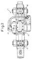
- FIG. 1 illustrates an embodiment of the invention wherein, as shown in Fig. 1, a main body 2 of a drifter 1 of the piercing apparatus is provided with a cylinder 3 for forward blowing and a cylinder 4 for reverse blowing arranged in series at a predetermined distance.
- Bushings 6 and 7 are provided at both front and rear ends of the cylinder 3 for forward blowing, and a hollow rear cap 5 in the shape of a bag is secured by bolts to the rear portion of the cylinder 3.
- a bushing 9 is provided in the inner surface of the rear cap 5.
- An intermediate cylinder 10 is connected between the cylinder 3 for forward blowing and the reverse-blowing unit.
- a chuck driver 13 having a tooth train 13a formed on the outer peripheral surface thereof is rotatably supported by bush in the inner periphery of the intermediate cylinder 10, and a chuck 15 is fitted into the chuck driver.
- the chuck 15 is divided into two chuck pieces 15a, 15b of nearly a fan shape, and a female spline 15c is formed in the inner surface of each of the chuck pieces 15a, 15b.
- the chuck driver 13 On the inner surface of the chuck driver 13 are formed protuberances 13a, 13a protruding in the direction of diameter, and the chuck pieces 15a, 15b, of nearly a fan shape fitted in the chuck driver, are brought into contact therewith so as to be coupled and secured.
- Bushings 16, 17 are provided at both front and rear ends of the cylinder 4 for reverse blowing connected to the front side of the intermediate cylinder 10, and a front head 19 having bushings 18, 19 provided in the inner surface side thereof is attached to the front side of the cylinder.
- a rod-like shank rod 20 is inserted in the main body 2 of the drifter 1.
- the shank rod 20 is provided with a junction portion 22 of a large diameter having an internally threaded portion 22a, and is further provided with a blowing portion 23 of a large diameter at the intermediate portion thereof and with a slide portion 24 at the rear end thereof.
- a gap portion 20a between the junction portion 22 and the blowing portion 23, and a gap portion 20b between the side portion 24 and the blowing portion, are in the form of a round rod of a small diameter.
- the blowing portion 23 of the shank rod 20 is formed nearly in the shape of a drum, both the front surface 23b and the rear surface 23a thereof serving as blowing surfaces.
- a male spline 25 is formed on the outer periphery of the blowing portion 23 and is fitted to the female spline 15c of the chuck.
- a cylindrical piston 30 for forward blowing is fitted onto the round rod portion 20b on the rear side of the shank rod 20, and a cylindrical piston 33 for reverse-blowing is fitted onto the round rod portion 20a of the front side.
- a small gap t is maintained between these pistons and the round rod portion, so that the pistons are allowed to freely move back and forth.
- the piston 30 for forward blowing and the piston 33 for reverse blowing have an equal size but are directed opposite to each other. Further, the cylinders 3 and 4 containing these front and rear pistons have the same shape and the same size, but are directed opposite to each other. Valve units 40, 43 for actuating the pistons are mounted on the outer peripheries of the cylinder 3 for forward blowing and of the cylinder 4 for reverse blowing.
- a pilot valve unit 45 for blowing is mounted on the upper surface on the outer periphery of the intermediate cylinder 10 of the drifter 1, and a rotary pilot valve unit 47 for changing the rotation over to the forward direction or the reverse direction is mounted on the side surface thereof.
- the rotary pilot valve unit 47 is shown in an expansion plan for the purpose of convenience and, hence, the two pilot valve devices 45 and 47 are shown being overlapped one upon the other.
- a rotary unit 50 is provided on the side surface of the intermediate cylinder 10 on the side opposite to the pilot valve unit 47.
- the rotary unit 50 includes a hydraulic motor 51 and a counter gear 52, the counter gear being in mesh with the tooth train 13a of the chuck driver 13, so that the rotation of the hydraulic motor 51 is transmitted to the chuck driver 13 through the counter gear 52.
- a high-pressure fluid enters into the pilot valve unit 45 for blowing through a port Pa when the drifter 1 moves forward and enters into the valve unit 40 for forward blowing passing through a port Pf to actuate the piston 32 for forward blowing.
- the return fluid at this moment is returned back to the fluid tank through port Pg, port Ph and port Pc.
- the high-pressure fluid enters into the pilot valve unit 45 for blowing through the port Pa when the drifter 1 moves back.
- the pressurized fluid acts upon the pilot port Pd from a feed-backward circuit for moving the drifter 1 backward.
- the valve 60 is changed over, and the pressurized fluid from the port Pa enters into the valve unit 43 for reverse blowing passing through the port Pi to actuate the piston 33 for reverse blowing.
- the return fluid is sent back to the fluid tank through port Pj, port Ph and port PC.
- the high-pressure fluid enters into the pilot valve unit 47 for rotation through the port Pb during the piercing, and reaches a forward rotation port P1 of the hydraulic motor 51 through the port Pk to rotate the shank rod 20 forward.
- the return fluid enters into the port Pn from the reverse rotation port Pm of the hydraulic motor 51, meets the return fluid from the blow return port Ph, and is returned back to the fluid tank through port Pc.
- the reverse rotation is used for removing the rod fitted into the threaded portion of the junction portion of the shank rod 20.
- the high-pressure fluid enters into the pilot valve unit 47 for rotation at the feed-backward end through the port Pb and, at the same time, the fluid pressurized high enough to overcome the pushing force of the spring 61 acts on the pilot port Pe through the pilot port Pd, whereby the valve 65 is changed over, so that the pressurized fluid arrives at a reverse rotation port Pm of the hydraulic motor 51 through port Pb and port Pn thereby to rotate the shank rod 20 in reverse.
- the return fluid at this moment enters into the port Pk from the forward rotation port P1 of the hydraulic motor 51, enters the blow return port Ph, and is returned back to the fluid tank through port PC.
- Figs 6 to 8 are diagrams of hydraulic conduits for operating the piercing apparatus 1, wherein local constitutions are slightly different depending upon the drawings.
- the drawings of these conduits do not include the conduits for swinging, moving up and down or centering up and down, the guide cell on which the drifter is mounted.
- the piercing apparatus 1 is provided with three thick hydraulic hoses, i.e., a hydraulic pressure feed hose (blow IN) Hi for blowing and rotating the drifter, a hydraulic pressure feed hose for rotation (rotation IN) Hr, and a return line (T-line) Ht returning from the blowing unit and the rotary unit.
- two hydraulic hoses i.e., a hydraulic hose Ha for feed forward and a hydraulic hose Hb for feed backward.
- a narrow pilot hose Hp for changing over the forward/reverse blow is connected to the conduit for feed backward, whereby a pilot pressure acts from the line of feed backward on the pilot valve Vp for changing over the forward/reverse blow so that, at the time of moving back, the blow is automatically changed over to the reverse blow.
- the rotation is usually in the forward direction.
- a forward/reverse change-over solenoid valve Vs of the valve unit provided in the valve stand is turned on, thereby to obtain the rotation in the reverse direction.
- Fig. 7 illustrates an example of conduits different from the above example.
- a narrow pilot hose Hp from the conduit for feed backward is connected to the valve Vs for changing over the rotation and to the pilot valve Vp for changing over the forward/reverse blow so that, when the load is exerted during the feed backward, the blow is automatically changed from the forward blow over to the reverse blow and the rotation is changed from the forward rotation over to the reverse rotation.
- the reverse blow is required at the time of withdrawing the rod (metal rod) or when the load is exerted during the feed backward, In order to prevent the screws from being loosened at the coupling portions, the drifter is rotated forward.
- the forward rotation is not changed over to the reverse rotation by the pilot pressure in the feed-backward circuit.
- the drifter must be rotated in reverse at the time when the operation is finished and the rod (metal rod) must be removed. In this case, the feed is brought to the backward limit, and the drifter is rotated in a state where the solenoid valve for backward motion is turned on (in a state where the pressure is exerted on the backward circuit); i.e., the drifter is rotated in the reverse direction.
- the method of Fig. 7 minimizes the number of conduits between the valve stand and the drifter.
- Fig. 8 illustrates a further different example of the conduits.
- the pilot valve for changing over the forward-reverse blow/forward-reverse rotation is actuated by an electromagnetic valve in the valve stand.
- the individual modes are selected relying on the combinations of operations of the electromagnetic valves. Then, the forward/reverse blow and the forward/reverse rotation can be arbitrarily selected and executed.
- Figs. 9 to 13 illustrate the reverse-blowing unit.
- the piston 33 is reaching the top dead center (front end position) and the high-pressure fluid acts on a rear piston chamber S1 from a high-pressure port D1.
- M1 > M2 between the pressure-receiving area M1 of the rear piston chamber S1 and the pressure-receiving area M2 of a front piston chamber S2.
- the piston 33 continues to move forward and during this period, the accumulator A supplies the lacking amount of operation fluid.
- the piston further proceeds, and the large diameter portion 33a thereof opens the valve change-over port D3 so that it is communicated with a port D2 of the low-pressure line LP. Then, the pressure in the valve change-over chamber S4 decreases and the valve V starts changing over.
- the piston 33 reaches a point of reverse blow, transmits the kinetic energy which it has gained during the stroke of reverse blow to the shank rod 20 which then transmits the energy of reverse blow to the bit.
- the valve V has been completely changed over, whereby the ports (D1, D2, D3) are all communicated with the low-pressure line LP, the force acting on the front part of the piston 33 becomes larger than the force acting on the rear part of the piston, and the piston enters into the stroke of moving backward.
- the piston closes the port D5, comes into a halt while forming a cushion chamber S3 and, then, starts moving backward.
- Fig. 13 the piston 33 for reverse blow continues to move backward and the valve V continues to be changed over. Then, the port D1 is communicated with the high-pressure line HP, and the high-pressure fluid enters into the rear piston chamber. Due to the inertial energy which the piston has gained during the stroke of backward movement, the rear piston chamber forms a cushion chamber in the high-pressure line, and the hydraulic pressure is accumulated in the accumulator A. As the valve V is completely changed over and the piston reaches the top dead center at where it is stopped by the cushion, the initial state of Fig. 7 is resumed.
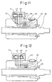
- Figs. 14 and 15 illustrate an example of using the piercing apparatus M as an iron runner port-opening machine for a blast furnace F, wherein the drifter 1 of the piercing apparatus M is attached to the guide cell 71 in a manner to move back and forth.
- the base portion of the guide cell 71 is supported by an arm 73 hanged from a swing base 72 via a shaft 74 so as to freely rotate up and down, and an intermediate portion thereof is supported by a lift unit 75.
- Reference numeral 77 denotes a hydraulic cylinder for lifting. Upon expanding and contracting the hydraulic cylinder 77, the guide cell turns up and down with the shaft 74 as a center.
- reference numeral 79 denotes a five-way swivel for the air and water
- 80 denotes an up-down centering unit for centering the guide cell in the up-and-down direction.
- the position of the end of the guide cell is adjusted in the up-and-down direction by forwardly or reversely rotating an air motor 81 for accomplishing the centering in the up-and-down direction.
- reference numeral 85 denotes a hydraulic feed motor constituting a feed unit F attached to the guide cell 71.
- a sprocket attached to the rotary shaft of the motor rotates, and a chain wrapped round the sprockets attached to the front end and the rear end of the guide cell moves back and forth.
- a carriage 87 is attached to the chain, and the drifter 1 is mounted on the carriage. Therefore, the drifter 1 moves back and forth accompanying the motion of the chain.
- Reference numeral 90 denotes a pump unit
- 91 denotes a valve unit (containing a small manifold electromagnetic block) for the drifter
- 92 denotes a valve unit containing an electromagnetic valve block for the lifting unit for raising and lowering the guide cell 71
- reference numeral 93 denotes a valve stand mounting a valve unit for swinging
- 95 denotes a safety hook rotated by an air cylinder 95a
- reference numeral 96 denotes an air electromagnetic valve box
- 97 denotes an encoder for detecting the depth of the hole.
- the valve unit 91 for the drifter is the one in which the valve for changing over whole or part of the hydraulic pressure supplied to the blowing unit, rotary unit and feed unit, and the valve for controlling the flow rate and pressure, are installed in a heat-resistant box mounted on the guide cell, and is provided with cooling means for forcibly cooling the interior of the heat-resistant box by purging the air or a like method.
- the valves that are contained in the box having resistance against the heat are protected from high temperatures when the apparatus is used for opening the iron running port of the blast furnace and, besides, the apparatus is realized in a compact size. It is further desired to contain, in the above heat-resistant box, the valve for changing over whole or part of the hydraulic pressure supplied to the pilot valve that changes over the directions of the blowing unit and of the rotary unit, as well as the valve for controlling the flow rate and pressure.
- a piercing rod R is connected to the shank rod 20 of the drifter 1, and a bit is attached to the end of the piercing rod.
- the direction and inclination of the drifter 1 are so adjusted that the bit comes in contact with a desired piercing portion, the feed unit is actuated to fit the bit to the piercing position (e.g., iron running port Fa of the blast furnace), and the forward-blowing unit and the rotary unit are actuated.
- the piercing operation is executed as desired.
- the drifter 1 After the piercing is effected to a predetermined depth, the drifter 1 is moved backward to withdraw the bit and the rod from the hole that is pierced. At this moment, the feed unit is changed over to the side of moving backward, whereby the pilot valve unit 45 operates, and the supply of hydraulic pressure for blowing is changed from the valve for forward blowing over to the valve for reverse blowing.
- the blowing is changed from the forward blow which gives blow to the rod in the forward direction over to the reverse blow which gives blow in the reverse direction. Even in case the bit cannot be withdrawn due to the pieces and scraps of the piercing operation in the hole on the back side of the bit, the blow in the reverse direction helps to easily withdraw the bit.
- the hydraulic pressure can be supplied from the hydraulic pump to the drifter 1 by using the hydraulic hose for forward blowing and the hydraulic hose for reverse blowing, and the return fluid from the blowing unit and the return fluid from the rotary unit are returned back to the fluid tank through the common hydraulic hose, making it possible to decrease the number of thick hydraulic hoses extending along the outer side, and the apparatus is realized in a compact size featuring easy operation.
- the rod connection portion of the shank rod is internally threaded enabling the external thread of the piercing rod to be directly screwed therein and connected. Compared to the prior art using a coupling sleeve, therefore, the blowing force can be efficiently transmitted. However, this portion may be constructed similarly to that of the prior art.
- the shank rod having, in the intermediate portion thereof, a blowing portion with blowing surfaces on the front and rear sides thereof is used as a shank rod of the drifter, cylindrical pistons are fitted to the front and rear sides of the blowing portion to apply forward/reverse blow by the pistons on the front and rear sides thereof. Therefore, the overall length is decreased to realize the apparatus in a compact size.
- the pilot valve is provided for changing over the forward blow and the reverse blow. At the time when the device for feeding the drifter is changed over to the side of backward motion, the pilot valve is operated to change the forward blow over to the reverse blow.
- the hydraulic pressure feed (IN) hose can be used in common for the forward blow and for the reverse blow.
- the return circuits of the blow and rotation are formed as a T-line, and the return fluids of the blow and rotation are returned back to the tank through the common return hose. Therefore, only three thick hoses are required, contributing to simplifying the external structure and improving the operability.
Landscapes
- Engineering & Computer Science (AREA)
- Chemical & Material Sciences (AREA)
- Mechanical Engineering (AREA)
- Materials Engineering (AREA)
- Metallurgy (AREA)
- Organic Chemistry (AREA)
- Manufacturing & Machinery (AREA)
- General Engineering & Computer Science (AREA)
- Physics & Mathematics (AREA)
- Fluid Mechanics (AREA)
- Fluid-Pressure Circuits (AREA)
- Earth Drilling (AREA)
- Blast Furnaces (AREA)
- Waste-Gas Treatment And Other Accessory Devices For Furnaces (AREA)
Applications Claiming Priority (2)
| Application Number | Priority Date | Filing Date | Title |
|---|---|---|---|
| JP12824199 | 1999-05-10 | ||
| JP12824199A JP3817617B2 (ja) | 1999-05-10 | 1999-05-10 | さく孔装置 |
Publications (2)
| Publication Number | Publication Date |
|---|---|
| EP1052294A1 true EP1052294A1 (de) | 2000-11-15 |
| EP1052294B1 EP1052294B1 (de) | 2005-08-03 |
Family
ID=14979998
Family Applications (1)
| Application Number | Title | Priority Date | Filing Date |
|---|---|---|---|
| EP00109187A Expired - Lifetime EP1052294B1 (de) | 1999-05-10 | 2000-05-09 | Vorrichtung zum Abstechen |
Country Status (6)
| Country | Link |
|---|---|
| US (2) | US6601655B1 (de) |
| EP (1) | EP1052294B1 (de) |
| JP (1) | JP3817617B2 (de) |
| KR (1) | KR100367469B1 (de) |
| BR (1) | BR0002095A (de) |
| DE (1) | DE60021649T2 (de) |
Cited By (1)
| Publication number | Priority date | Publication date | Assignee | Title |
|---|---|---|---|---|
| CN108120557A (zh) * | 2016-11-30 | 2018-06-05 | 罗伯特·博世有限公司 | 箱组件的泄漏检查设备 |
Families Citing this family (9)
| Publication number | Priority date | Publication date | Assignee | Title |
|---|---|---|---|---|
| JP3817617B2 (ja) * | 1999-05-10 | 2006-09-06 | 新日本製鐵株式会社 | さく孔装置 |
| WO2007095964A1 (de) * | 2006-02-21 | 2007-08-30 | Festo Ag & Co. Kg | Pneumatisches antriebssystem |
| JP4944577B2 (ja) * | 2006-11-14 | 2012-06-06 | 株式会社丸和技研 | 出銑口開孔装置 |
| KR102224271B1 (ko) * | 2014-01-31 | 2021-03-05 | 후루까와 로크 드릴 가부시끼가이샤 | 액압식 타격 장치 |
| KR101570692B1 (ko) * | 2015-01-07 | 2015-11-20 | 주식회사 에이와이중공업 | 유압 브레이커 |
| US20160221171A1 (en) * | 2015-02-02 | 2016-08-04 | Caterpillar Inc. | Hydraulic hammer having dual valve acceleration control system |
| CA3029255A1 (en) * | 2016-06-24 | 2017-12-28 | Berry Metal Company | Pneumatic drilling device |
| KR102163473B1 (ko) * | 2016-08-31 | 2020-10-08 | 후루까와 로크 드릴 가부시끼가이샤 | 액압식 타격장치 |
| CN113458859A (zh) * | 2021-08-19 | 2021-10-01 | 青岛新力通工业有限责任公司 | 一种带有尾座功能的车镗一体授油器 |
Citations (5)
| Publication number | Priority date | Publication date | Assignee | Title |
|---|---|---|---|---|
| US5259464A (en) * | 1991-04-24 | 1993-11-09 | Krupp Maschinentechnik Gesellschaft Mit Beschrankter Haftung | Percussion mechanism for a drill rod unit |
| US5348430A (en) * | 1992-06-10 | 1994-09-20 | Paul Wurth S.A. | Universal chuck for a machine for piercing a tap hole of a shaft furnace |
| DE4404009C1 (de) * | 1994-02-09 | 1995-04-27 | Klemm Guenter | Fluidbetätigter Schlaghammer |
| US5520254A (en) * | 1993-12-21 | 1996-05-28 | Gunter Klemm | Fluid-actuated impact hammer |
| EP0930476A1 (de) * | 1998-01-19 | 1999-07-21 | BÖHLER PNEUMATIK INTERNATIONAL GESELLSCHAFT m.b.H. | Verfahren zum Offenstellen oder zum Verschliessen einer Abstichöffnung eines metallurgischen Gefässes und Hammereinrichtung, insbesondere zur Durchführung des Verfahrens |
Family Cites Families (10)
| Publication number | Priority date | Publication date | Assignee | Title |
|---|---|---|---|---|
| US3955478A (en) * | 1973-10-29 | 1976-05-11 | Dresser Industries, Inc. | Hydraulically powered percussion drill |
| US5040618A (en) * | 1989-04-24 | 1991-08-20 | Cannon Industries, Inc. | Pneumatic drill |
| US5060734A (en) * | 1989-09-11 | 1991-10-29 | United States Of America | Seawater hydraulic rock drill |
| US5258464A (en) | 1990-01-29 | 1993-11-02 | Shell Oil Company | Impact copolymer compositions |
| DE4028595A1 (de) * | 1990-09-08 | 1992-03-12 | Krupp Maschinentechnik | Hydraulisch betriebenes schlagwerk |
| JPH06108770A (ja) * | 1992-08-31 | 1994-04-19 | Sig (Schweiz Ind Ges) | ロックドリル用ドリル装置 |
| FR2699229B1 (fr) * | 1992-12-11 | 1995-03-10 | Poclain Hydraulics Sa | Groupe moteur hydraulique d'entraînement d'un outil de forage. |
| JPH06322420A (ja) | 1993-05-11 | 1994-11-22 | Nippon Steel Corp | 出銑口開孔機 |
| JPH1036905A (ja) | 1996-07-19 | 1998-02-10 | Yamamoto Lock Mach Kk | 出銑口開孔用削岩機 |
| JP3817617B2 (ja) * | 1999-05-10 | 2006-09-06 | 新日本製鐵株式会社 | さく孔装置 |
-
1999
- 1999-05-10 JP JP12824199A patent/JP3817617B2/ja not_active Expired - Fee Related
-
2000
- 2000-05-09 DE DE60021649T patent/DE60021649T2/de not_active Expired - Lifetime
- 2000-05-09 EP EP00109187A patent/EP1052294B1/de not_active Expired - Lifetime
- 2000-05-09 US US09/567,640 patent/US6601655B1/en not_active Expired - Fee Related
- 2000-05-10 BR BR0002095-8A patent/BR0002095A/pt not_active IP Right Cessation
- 2000-05-10 KR KR10-2000-0024954A patent/KR100367469B1/ko not_active IP Right Cessation
-
2003
- 2003-03-05 US US10/379,772 patent/US6698532B2/en not_active Expired - Fee Related
Patent Citations (5)
| Publication number | Priority date | Publication date | Assignee | Title |
|---|---|---|---|---|
| US5259464A (en) * | 1991-04-24 | 1993-11-09 | Krupp Maschinentechnik Gesellschaft Mit Beschrankter Haftung | Percussion mechanism for a drill rod unit |
| US5348430A (en) * | 1992-06-10 | 1994-09-20 | Paul Wurth S.A. | Universal chuck for a machine for piercing a tap hole of a shaft furnace |
| US5520254A (en) * | 1993-12-21 | 1996-05-28 | Gunter Klemm | Fluid-actuated impact hammer |
| DE4404009C1 (de) * | 1994-02-09 | 1995-04-27 | Klemm Guenter | Fluidbetätigter Schlaghammer |
| EP0930476A1 (de) * | 1998-01-19 | 1999-07-21 | BÖHLER PNEUMATIK INTERNATIONAL GESELLSCHAFT m.b.H. | Verfahren zum Offenstellen oder zum Verschliessen einer Abstichöffnung eines metallurgischen Gefässes und Hammereinrichtung, insbesondere zur Durchführung des Verfahrens |
Cited By (1)
| Publication number | Priority date | Publication date | Assignee | Title |
|---|---|---|---|---|
| CN108120557A (zh) * | 2016-11-30 | 2018-06-05 | 罗伯特·博世有限公司 | 箱组件的泄漏检查设备 |
Also Published As
| Publication number | Publication date |
|---|---|
| EP1052294B1 (de) | 2005-08-03 |
| KR100367469B1 (ko) | 2003-01-10 |
| BR0002095A (pt) | 2001-01-02 |
| JP3817617B2 (ja) | 2006-09-06 |
| DE60021649T2 (de) | 2006-01-12 |
| KR20010066789A (ko) | 2001-07-11 |
| US20030136569A1 (en) | 2003-07-24 |
| DE60021649D1 (de) | 2005-09-08 |
| US6698532B2 (en) | 2004-03-02 |
| US6601655B1 (en) | 2003-08-05 |
| JP2000328116A (ja) | 2000-11-28 |
Similar Documents
| Publication | Publication Date | Title |
|---|---|---|
| EP1052294B1 (de) | Vorrichtung zum Abstechen | |
| US5613568A (en) | Rock drilling machine | |
| US4301723A (en) | Cylinder operated swinging ram cutoff press | |
| US3945443A (en) | Steerable rock boring head for earth boring machines | |
| GB1507605A (en) | Device for damping the recoil of a work tool connected to a percussion tool | |
| US9701003B2 (en) | Hydraulic hammer having delayed automatic shutoff | |
| US6896077B1 (en) | Rotary driven pipe-bursting tool | |
| JP4948879B2 (ja) | 割岩装置、割岩装置用アタッチメントおよび割岩装置用圧油供給装置並びに割岩用作業車両 | |
| JP3419591B2 (ja) | 制御可能な打撃数および打撃エネルギーを有する液圧打撃装置 | |
| EP1907662B1 (de) | Hydraulikkreisvorrichtung | |
| CN1325758C (zh) | 盾构机中能调节开口率的装置 | |
| AU781874B2 (en) | Device for hydraulic power supply of a rotary apparatus for percussive drilling | |
| JP2007039220A (ja) | 回転伸縮ジャッキ | |
| CN216009772U (zh) | 一种便于调节的管道托架 | |
| US4397175A (en) | Apparatus for controlling the movement of a reciprocatory hydraulically driven element | |
| US4474253A (en) | Apparatus for producing an upwardly directed drill hole | |
| US6321778B1 (en) | Apparatus for pipeline construction | |
| AU2012101626A4 (en) | Guide for drilling tool, and drilling unit | |
| KR20190118909A (ko) | 원격 조정이 가능한 암반파쇄 유압잭용 유압공급장치 | |
| CN212296225U (zh) | 一种一体式水平旋转机械手 | |
| EP3865714B1 (de) | Anordnung umfassend einen pneumatischen zylinder mit beschleuniger | |
| JPH10148083A (ja) | ボーリング用チャック装置 | |
| SU1719634A1 (ru) | Устройство дл образовани разгрузочных пазов в угольном массиве | |
| FI58385C (fi) | Hydrauldriven borrmaskin med reglerbar slagenergi hos kolven | |
| CN117957357A (zh) | 具有空转模式的水平定向钻机 |
Legal Events
| Date | Code | Title | Description |
|---|---|---|---|
| PUAI | Public reference made under article 153(3) epc to a published international application that has entered the european phase |
Free format text: ORIGINAL CODE: 0009012 |
|
| 17P | Request for examination filed |
Effective date: 20000607 |
|
| AK | Designated contracting states |
Kind code of ref document: A1 Designated state(s): DE FR GB IT |
|
| AX | Request for extension of the european patent |
Free format text: AL;LT;LV;MK;RO;SI |
|
| RIN1 | Information on inventor provided before grant (corrected) |
Inventor name: TAKAO, HIROYUKI, NIPPON STEEL CORP. Inventor name: HONTANI, MANPEI, YAMAMOTO ROCK MACHINE CO. LTD. Inventor name: HAGA, KAZUO, YAMAMOTO ROCK MACHINE CO. LTD. Inventor name: MORIMITSU, KEISUKE C/O NIPPON STEEL CORPORATION Inventor name: YATAGI, YOSHIICHI, YAMAMOTO ROCK MACHINE CO. LTD. Inventor name: GOTOU, MANABU C/O NIPPON STEEL CORPORATION Inventor name: KAWAKAMI, HIROMI, YAMAMOTO ROCK MACHINE CO. LTD. Inventor name: IWASAKI, TUNEOMI, YAMAMOTO ROCK MACHINE CO. LTD. |
|
| AKX | Designation fees paid |
Free format text: DE FR GB IT |
|
| 17Q | First examination report despatched |
Effective date: 20031124 |
|
| GRAP | Despatch of communication of intention to grant a patent |
Free format text: ORIGINAL CODE: EPIDOSNIGR1 |
|
| GRAS | Grant fee paid |
Free format text: ORIGINAL CODE: EPIDOSNIGR3 |
|
| GRAA | (expected) grant |
Free format text: ORIGINAL CODE: 0009210 |
|
| AK | Designated contracting states |
Kind code of ref document: B1 Designated state(s): DE FR GB IT |
|
| REG | Reference to a national code |
Ref country code: GB Ref legal event code: FG4D |
|
| REF | Corresponds to: |
Ref document number: 60021649 Country of ref document: DE Date of ref document: 20050908 Kind code of ref document: P |
|
| ET | Fr: translation filed | ||
| PLBE | No opposition filed within time limit |
Free format text: ORIGINAL CODE: 0009261 |
|
| STAA | Information on the status of an ep patent application or granted ep patent |
Free format text: STATUS: NO OPPOSITION FILED WITHIN TIME LIMIT |
|
| 26N | No opposition filed |
Effective date: 20060504 |
|
| REG | Reference to a national code |
Ref country code: DE Ref legal event code: R082 Ref document number: 60021649 Country of ref document: DE Representative=s name: VOSSIUS & PARTNER, DE |
|
| REG | Reference to a national code |
Ref country code: DE Ref legal event code: R081 Ref document number: 60021649 Country of ref document: DE Owner name: YAMAMOTO ROCK MACHINE CO., LTD., JP Free format text: FORMER OWNER: NIPPON STEEL CORP., YAMAMOTO ROCK MACHINE CO., LTD., NITTETSU PLANT DESIGNING CORP., , JP Effective date: 20130422 Ref country code: DE Ref legal event code: R081 Ref document number: 60021649 Country of ref document: DE Owner name: NITTETSU PLANT DESIGNING CORP., JP Free format text: FORMER OWNER: NIPPON STEEL CORP., YAMAMOTO ROCK MACHINE CO., LTD., NITTETSU PLANT DESIGNING CORP., , JP Effective date: 20130422 Ref country code: DE Ref legal event code: R082 Ref document number: 60021649 Country of ref document: DE Representative=s name: VOSSIUS & PARTNER, DE Effective date: 20130422 Ref country code: DE Ref legal event code: R081 Ref document number: 60021649 Country of ref document: DE Owner name: NIPPON STEEL & SUMITOMO METAL CORPORATION, JP Free format text: FORMER OWNER: NIPPON STEEL CORP., YAMAMOTO ROCK MACHINE CO., LTD., NITTETSU PLANT DESIGNING CORP., , JP Effective date: 20130422 Ref country code: DE Ref legal event code: R081 Ref document number: 60021649 Country of ref document: DE Owner name: NITTETSU PLANT DESIGNING CORP., KITAKYUSHI, JP Free format text: FORMER OWNER: NIPPON STEEL CORP., YAMAMOTO ROCK MACHINE CO., LTD., NITTETSU PLANT DESIGNING CORP., , JP Effective date: 20130422 Ref country code: DE Ref legal event code: R082 Ref document number: 60021649 Country of ref document: DE Representative=s name: VOSSIUS & PARTNER PATENTANWAELTE RECHTSANWAELT, DE Effective date: 20130422 Ref country code: DE Ref legal event code: R081 Ref document number: 60021649 Country of ref document: DE Owner name: YAMAMOTO ROCK MACHINE CO., LTD., JP Free format text: FORMER OWNERS: NIPPON STEEL CORP., TOKIO/TOKYO, JP; YAMAMOTO ROCK MACHINE CO., LTD., TOKIO/TOKYO, JP; NITTETSU PLANT DESIGNING CORP., KITAKYUSHI, FUKUOKA, JP Effective date: 20130422 Ref country code: DE Ref legal event code: R081 Ref document number: 60021649 Country of ref document: DE Owner name: NIPPON STEEL & SUMITOMO METAL CORPORATION, JP Free format text: FORMER OWNERS: NIPPON STEEL CORP., TOKIO/TOKYO, JP; YAMAMOTO ROCK MACHINE CO., LTD., TOKIO/TOKYO, JP; NITTETSU PLANT DESIGNING CORP., KITAKYUSHI, FUKUOKA, JP Effective date: 20130422 Ref country code: DE Ref legal event code: R081 Ref document number: 60021649 Country of ref document: DE Owner name: NITTETSU PLANT DESIGNING CORP., KITAKYUSHI, JP Free format text: FORMER OWNERS: NIPPON STEEL CORP., TOKIO/TOKYO, JP; YAMAMOTO ROCK MACHINE CO., LTD., TOKIO/TOKYO, JP; NITTETSU PLANT DESIGNING CORP., KITAKYUSHI, FUKUOKA, JP Effective date: 20130422 |
|
| PGFP | Annual fee paid to national office [announced via postgrant information from national office to epo] |
Ref country code: DE Payment date: 20130515 Year of fee payment: 14 Ref country code: GB Payment date: 20130508 Year of fee payment: 14 |
|
| PGFP | Annual fee paid to national office [announced via postgrant information from national office to epo] |
Ref country code: FR Payment date: 20130531 Year of fee payment: 14 |
|
| REG | Reference to a national code |
Ref country code: DE Ref legal event code: R119 Ref document number: 60021649 Country of ref document: DE |
|
| GBPC | Gb: european patent ceased through non-payment of renewal fee |
Effective date: 20140509 |
|
| REG | Reference to a national code |
Ref country code: FR Ref legal event code: ST Effective date: 20150130 |
|
| REG | Reference to a national code |
Ref country code: DE Ref legal event code: R119 Ref document number: 60021649 Country of ref document: DE Effective date: 20141202 |
|
| PG25 | Lapsed in a contracting state [announced via postgrant information from national office to epo] |
Ref country code: DE Free format text: LAPSE BECAUSE OF NON-PAYMENT OF DUE FEES Effective date: 20141202 |
|
| PG25 | Lapsed in a contracting state [announced via postgrant information from national office to epo] |
Ref country code: GB Free format text: LAPSE BECAUSE OF NON-PAYMENT OF DUE FEES Effective date: 20140509 Ref country code: FR Free format text: LAPSE BECAUSE OF NON-PAYMENT OF DUE FEES Effective date: 20140602 |
|
| PGFP | Annual fee paid to national office [announced via postgrant information from national office to epo] |
Ref country code: IT Payment date: 20160524 Year of fee payment: 17 |
|
| PG25 | Lapsed in a contracting state [announced via postgrant information from national office to epo] |
Ref country code: IT Free format text: LAPSE BECAUSE OF NON-PAYMENT OF DUE FEES Effective date: 20170509 |