EP1052211A2 - A core pipe for a sheet roll - Google Patents
A core pipe for a sheet roll Download PDFInfo
- Publication number
- EP1052211A2 EP1052211A2 EP00116709A EP00116709A EP1052211A2 EP 1052211 A2 EP1052211 A2 EP 1052211A2 EP 00116709 A EP00116709 A EP 00116709A EP 00116709 A EP00116709 A EP 00116709A EP 1052211 A2 EP1052211 A2 EP 1052211A2
- Authority
- EP
- European Patent Office
- Prior art keywords
- sheet
- roll
- core pipe
- tension
- paper
- Prior art date
- Legal status (The legal status is an assumption and is not a legal conclusion. Google has not performed a legal analysis and makes no representation as to the accuracy of the status listed.)
- Granted
Links
Images


Classifications
-
- B—PERFORMING OPERATIONS; TRANSPORTING
- B65—CONVEYING; PACKING; STORING; HANDLING THIN OR FILAMENTARY MATERIAL
- B65H—HANDLING THIN OR FILAMENTARY MATERIAL, e.g. SHEETS, WEBS, CABLES
- B65H23/00—Registering, tensioning, smoothing or guiding webs
- B65H23/04—Registering, tensioning, smoothing or guiding webs longitudinally
- B65H23/06—Registering, tensioning, smoothing or guiding webs longitudinally by retarding devices, e.g. acting on web-roll spindle
- B65H23/063—Registering, tensioning, smoothing or guiding webs longitudinally by retarding devices, e.g. acting on web-roll spindle and controlling web tension
-
- B—PERFORMING OPERATIONS; TRANSPORTING
- B65—CONVEYING; PACKING; STORING; HANDLING THIN OR FILAMENTARY MATERIAL
- B65H—HANDLING THIN OR FILAMENTARY MATERIAL, e.g. SHEETS, WEBS, CABLES
- B65H75/00—Storing webs, tapes, or filamentary material, e.g. on reels
- B65H75/02—Cores, formers, supports, or holders for coiled, wound, or folded material, e.g. reels, spindles, bobbins, cop tubes, cans, mandrels or chucks
- B65H75/04—Kinds or types
- B65H75/08—Kinds or types of circular or polygonal cross-section
- B65H75/10—Kinds or types of circular or polygonal cross-section without flanges, e.g. cop tubes
-
- B—PERFORMING OPERATIONS; TRANSPORTING
- B65—CONVEYING; PACKING; STORING; HANDLING THIN OR FILAMENTARY MATERIAL
- B65B—MACHINES, APPARATUS OR DEVICES FOR, OR METHODS OF, PACKAGING ARTICLES OR MATERIALS; UNPACKING
- B65B41/00—Supplying or feeding container-forming sheets or wrapping material
- B65B41/12—Feeding webs from rolls
-
- B—PERFORMING OPERATIONS; TRANSPORTING
- B65—CONVEYING; PACKING; STORING; HANDLING THIN OR FILAMENTARY MATERIAL
- B65B—MACHINES, APPARATUS OR DEVICES FOR, OR METHODS OF, PACKAGING ARTICLES OR MATERIALS; UNPACKING
- B65B57/00—Automatic control, checking, warning, or safety devices
- B65B57/02—Automatic control, checking, warning, or safety devices responsive to absence, presence, abnormal feed, or misplacement of binding or wrapping material, containers, or packages
- B65B57/04—Automatic control, checking, warning, or safety devices responsive to absence, presence, abnormal feed, or misplacement of binding or wrapping material, containers, or packages and operating to control, or to stop, the feed of such material, containers, or packages
-
- B—PERFORMING OPERATIONS; TRANSPORTING
- B65—CONVEYING; PACKING; STORING; HANDLING THIN OR FILAMENTARY MATERIAL
- B65H—HANDLING THIN OR FILAMENTARY MATERIAL, e.g. SHEETS, WEBS, CABLES
- B65H16/00—Unwinding, paying-out webs
- B65H16/005—Dispensers, i.e. machines for unwinding only parts of web roll
-
- B—PERFORMING OPERATIONS; TRANSPORTING
- B65—CONVEYING; PACKING; STORING; HANDLING THIN OR FILAMENTARY MATERIAL
- B65H—HANDLING THIN OR FILAMENTARY MATERIAL, e.g. SHEETS, WEBS, CABLES
- B65H16/00—Unwinding, paying-out webs
- B65H16/10—Arrangements for effecting positive rotation of web roll
- B65H16/103—Arrangements for effecting positive rotation of web roll in which power is applied to web-roll spindle
-
- B—PERFORMING OPERATIONS; TRANSPORTING
- B65—CONVEYING; PACKING; STORING; HANDLING THIN OR FILAMENTARY MATERIAL
- B65H—HANDLING THIN OR FILAMENTARY MATERIAL, e.g. SHEETS, WEBS, CABLES
- B65H26/00—Warning or safety devices, e.g. automatic fault detectors, stop-motions, for web-advancing mechanisms
- B65H26/06—Warning or safety devices, e.g. automatic fault detectors, stop-motions, for web-advancing mechanisms responsive to predetermined lengths of webs
-
- B—PERFORMING OPERATIONS; TRANSPORTING
- B65—CONVEYING; PACKING; STORING; HANDLING THIN OR FILAMENTARY MATERIAL
- B65H—HANDLING THIN OR FILAMENTARY MATERIAL, e.g. SHEETS, WEBS, CABLES
- B65H26/00—Warning or safety devices, e.g. automatic fault detectors, stop-motions, for web-advancing mechanisms
- B65H26/08—Warning or safety devices, e.g. automatic fault detectors, stop-motions, for web-advancing mechanisms responsive to a predetermined diameter
-
- B—PERFORMING OPERATIONS; TRANSPORTING
- B65—CONVEYING; PACKING; STORING; HANDLING THIN OR FILAMENTARY MATERIAL
- B65H—HANDLING THIN OR FILAMENTARY MATERIAL, e.g. SHEETS, WEBS, CABLES
- B65H75/00—Storing webs, tapes, or filamentary material, e.g. on reels
- B65H75/02—Cores, formers, supports, or holders for coiled, wound, or folded material, e.g. reels, spindles, bobbins, cop tubes, cans, mandrels or chucks
- B65H75/18—Constructional details
- B65H75/182—Identification means
-
- B—PERFORMING OPERATIONS; TRANSPORTING
- B65—CONVEYING; PACKING; STORING; HANDLING THIN OR FILAMENTARY MATERIAL
- B65H—HANDLING THIN OR FILAMENTARY MATERIAL, e.g. SHEETS, WEBS, CABLES
- B65H2511/00—Dimensions; Position; Numbers; Identification; Occurrences
- B65H2511/10—Size; Dimensions
- B65H2511/11—Length
- B65H2511/114—Remaining length of web roll
-
- B—PERFORMING OPERATIONS; TRANSPORTING
- B65—CONVEYING; PACKING; STORING; HANDLING THIN OR FILAMENTARY MATERIAL
- B65H—HANDLING THIN OR FILAMENTARY MATERIAL, e.g. SHEETS, WEBS, CABLES
- B65H2511/00—Dimensions; Position; Numbers; Identification; Occurrences
- B65H2511/10—Size; Dimensions
- B65H2511/14—Diameter, e.g. of roll or package
-
- B—PERFORMING OPERATIONS; TRANSPORTING
- B65—CONVEYING; PACKING; STORING; HANDLING THIN OR FILAMENTARY MATERIAL
- B65H—HANDLING THIN OR FILAMENTARY MATERIAL, e.g. SHEETS, WEBS, CABLES
- B65H2513/00—Dynamic entities; Timing aspects
- B65H2513/10—Speed
- B65H2513/11—Speed angular
-
- B—PERFORMING OPERATIONS; TRANSPORTING
- B65—CONVEYING; PACKING; STORING; HANDLING THIN OR FILAMENTARY MATERIAL
- B65H—HANDLING THIN OR FILAMENTARY MATERIAL, e.g. SHEETS, WEBS, CABLES
- B65H2553/00—Sensing or detecting means
- B65H2553/20—Sensing or detecting means using electric elements
- B65H2553/22—Magnetic detectors, e.g. Hall detectors
-
- B—PERFORMING OPERATIONS; TRANSPORTING
- B65—CONVEYING; PACKING; STORING; HANDLING THIN OR FILAMENTARY MATERIAL
- B65H—HANDLING THIN OR FILAMENTARY MATERIAL, e.g. SHEETS, WEBS, CABLES
- B65H2553/00—Sensing or detecting means
- B65H2553/40—Sensing or detecting means using optical, e.g. photographic, elements
-
- B—PERFORMING OPERATIONS; TRANSPORTING
- B65—CONVEYING; PACKING; STORING; HANDLING THIN OR FILAMENTARY MATERIAL
- B65H—HANDLING THIN OR FILAMENTARY MATERIAL, e.g. SHEETS, WEBS, CABLES
- B65H2553/00—Sensing or detecting means
- B65H2553/51—Encoders, e.g. linear
-
- B—PERFORMING OPERATIONS; TRANSPORTING
- B65—CONVEYING; PACKING; STORING; HANDLING THIN OR FILAMENTARY MATERIAL
- B65H—HANDLING THIN OR FILAMENTARY MATERIAL, e.g. SHEETS, WEBS, CABLES
- B65H2801/00—Application field
- B65H2801/81—Packaging machines
Definitions
- the present invention relates to a core pipe for a sheet roll.
- One conventional drug packaging device includes a sheet feed unit rotatably supporting a rolled sheet of heat-fusible packaging paper, and a sealing device provided in a feed path through which the packaging sheet is unwound and fed. Upstream of the sealing device, the sheet is folded in half, drugs are supplied, and the sheet is heat-sealed in the width direction and along the edges by the sealing device to seal the drugs.
- Examined Japanese utility model publication discloses a sheet tension adjusting device which can apply uniform tension to the sheet even if the diameter of the sheet roll changes.
- the sheet tension adjusting device disclosed in this publication has a roll support cylinder on which is detachably mounted a sheet roll.
- a plurality of roll diameter detection sensors are provided at the side of the sheet roll. Signals from these detection sensors are used to control the electromagnetic force produced by an electromagnetic brake provided in the roll support cylinder so that the baking force decreases stepwise as the roll diameter decreases.
- the sheet length of the sheet which changes as the sheet is unwound, is detected stepwise by the roll diameter sensors arranged in the diametric direction of the roll.
- the braking force rank of the electromagnetic brake will fluctuate up and down for every rotation due to deviation of the axis of the core shaft, the weight of the sheet, or winding strain.
- Light reflecting type detection sensors have a problem in that they are more likely to malfunction.
- Packaging sheets used for a drug packaging device include semitransparent, or transparent heat-fusible paper and many other kinds of paper. If the end position of such a sheet changes, light is reflected differently, making it impossible to detect the reflected light as a signal. This deteriorates detecting accuracy. Further, it tends to meander under the influence of humidity variations. Detection accuracy may deteriorate due to uneven end faces.
- US-A 4,286,757 discloses a method and an apparatus for controlling the braking system for an unwinder comprising a roll of paper, which is supported at its core by a spindle and comprising braking friction pads which are operated by pressurized air and controlled by a control unit which receives signals from the tachometer-generator outputting a turning signal of the rotating roll and producing a signal to a paper tensioning device for such presenting a desired tension in the following processing stations.
- this braking control system for an unwinder of the paper roll cannot prevent that the tension of pulling off the paper from the roll fluctuates so wildly that the paper sheet may be stretched unevenly or distorted, thus, making it difficult to present uniform quality for such a sheet.
- a core pipe for a sheet roll comprising a hollow core pipe having a predetermined length for winding a sheet therearound, and magnets provided on the inner periphery of said hollow core pipe near one end thereof at angular intervals determined such that the amount and diameter of the sheet roll wound therearound can be calculated by an angle sensor provided on a fixed shaft, said hollow core pipe being rotatable together with a hollow shaft rotatably mounted around said fixed shaft.
- Such a core pipe for a sheet roll wherein said hollow shaft is inserted through said hollow core pipe, and wherein means for allowing said hollow core pipe to rotate together with said hollow shaft, comprises magnetizable members provided on an end face of said hollow core pipe, and a magnet provided on said hollow shaft.
- the tension in a sheet is adjusted by bringing a braking means into engagement with a roll support cylinder rotatably mounted around a nonrotatably supported support shaft, measuring the length of a sheet being fed from a roll of paper mounted on the roll support cylinder with a sheet length measuring sensor, calculating the winding length of the roll of paper after the sheet has been fed by subtracting the sheet length measured by the sheet length measuring sensor from a prestored maximum sheet length of the roll, calculating the current diameter of the roll based on the winding length of the roll and the thickness of the sheet, and adjusting the tension in the sheet by controlling the braking force of the brake means in a stepwise manner according to the current diameter of the roll.
- the sheet length measuring sensor may be a sheet feed length detection sensor provided in a sheet feed path, or an angle sensor provided on the roll support cylinder for determining the sheet feed length based on the rotation angle of the roll support cylinder.
- the tension in a sheet may also be adjusted by bringing a braking means into engagement with a roll support cylinder rotatably mounted around a nonrotatably supported support shaft, detecting the length of a sheet being fed from a roll of paper mounted on the roll support cylinder with a sheet length measuring sensor, detecting the rotation angle of the roll support cylinder with an angle sensor, calculating the current paper length of the roll based on the sheet length or the rotation angle measured by either sensor, and adjusting the tension in the sheet by controlling the braking force of the brake means in a stepwise manner according to the diameter of the roll corresponding to the current paper length of the roll.
- the sheet length is measured by a single sheet length measuring sensor.
- Such a full roll length does not necessarily have to be an actually measured value but may be approximately calculated based on the roll diameter and the sheet thickness. Such an approximately calculated value is sufficient to adjust the sheet tension because the braking force is adjusted roughly in a stepwise manner according to the changing diameter of the paper roll.
- the full roll length is not the full length of an intended end product, for example, even if the roll has been half used, it is possible to calculate the current roll length if the full roll length and diameter are known.
- the current roll diameter is calculated.
- the current roll diameter thus obtained is used to adjust the sheet tension by selecting an optimum brake force in a stepwise manner.
- Signals are detected by the sheet length measuring sensor and the angle sensor. Based on the change in one signal relative to the other, a change in the roll length is directly measured.
- a special mode is carried out before a normal mode in which the tension in the sheet is adjusted while the sheet is being fed, the special mode including calculating the paper winding length of the roll based on the signals from the sheet length sensor and the angle sensor in the same manner as in the normal mode by an inching operation in which the sheet is intermittently fed by a predetermined length, and adjusting the braking force to an intermediate level before the start of the normal mode based on the roll diameter calculated from the paper winding length to adjust the tension in the sheet beforehand.
- Any deviation in position between the roll support cylinder and the paper roll detachably mounted on the roll support cylinder is detected in the normal mode and/or the special mode based on an inconsistency between the signal from an angle sensor provided between the roll support cylinder and a support plate of the support shaft for detecting the rotation angle of the roll support cylinder and the signal from the angle sensor provided between the paper roll and the support shaft for detecting the rotation angle of the paper roll.
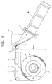
- Fig. 1 is a schematic diagram of a drug packaging machine showing mainly a paper feed unit and a packaging unit.
- the paper feed unit has a support shaft 1 on which is rotatably mounted a core pipe P on which is wound a roll R of a drug packaging paper sheet S.
- the sheet S is unwound from the roll R, and fed through feed rollers 2, 3 to the packaging unit.
- the sheet In the packaging unit, the sheet is longitudinally folded in half by a triangular plate 4. Drugs are dropped into the space defined in the folded sheet. The sheet is then heat-sealed widthwise and along both side edges at predetermined intervals by heating rollers 6 with perforators. While the packaging unit includes numerous other parts, only essential parts are shown for simplicity.
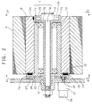
- Fig. 2 is a partial vertical section of the paper feed unit in which the roll paper R and the core pipe P are set.
- the support shaft 1 comprises a center shaft la having one end thereof fixed to a support plate 11 by a nut, an outer shaft 1b integrally mounted around the center shaft 1a, and a hollow shaft 1c rotatably mounted on the outer shaft 1b through bearings 12 provided near both ends of the outer shaft 1b.
- the center shaft la has a shaft head 13 at one end.
- the outer shaft 1b has a flange 14 at the same one end.
- the hollow shaft 1c has a flange 15 at the other end.
- the core pipe P and the roll paper R, mounted on the hollow shaft 1c, are rotatable relative to the support shaft 1.
- a plurality of magnets 16 are provided on the inner peripheral surface of the flange 15 at suitable intervals.
- Ferromagnetic (iron) members 17 are provided along the circumference of an end face of the core pipe P. The magnets 16 attract the ferromagnetic member 17 to detachably mount the core pipe P and the roll paper R on the hollow shaft 1c.
- Packaging sheet S unwound from the roll paper R is suitably tensioned by a motor brake 20 engaging the hollow shaft 1c.
- the motor brake 20, mounted on the support plate 11, is connected to a gear unit 21 through a transmission belt, not shown.
- the gear unit 21 has an output shaft on which is mounted a pinion 22 in mesh with a large gear 23 provided on the outer peripheral surface of the flange 15.
- braking force is applied to the hollow shaft 1c.
- the motor brake 20 is a small AC motor powered by a DC voltage. As will be described below, braking force is variable in four stages according to the tension in the packaging sheet S being unwound by changing the DC voltage applied in four stages.
- Magnets 24, Hall element sensors 25, a proximity switch 26 and projections 27 are described in the second embodiment.
- Fig. 3 schematically shows a brake circuit for controlling various parts of the device for feeding packaging sheet from the paper feed unit and packaging drugs.
- Its control unit 30 receives signals from an end sensor 31, those from a rotary encoder 32 provided near the feed rollers 3, and those from a revolving speed counter 33 mounted on the output shaft of a motor 6a coupled to the shaft of one of the heating rollers 6, and produces, based on one of the above signals, outputs for activating the motor brake 20 or the motor 6a.
- Numeral 34 indicates an input unit for inputting external data.
- Drugs are packaged while adjusting the tension in the packaging sheet with the sheet tension adjusting device of the first embodiment.
- the maximum diameter dmax and the minimum diameter do of the roll paper R to be set in the paper feed unit are known beforehand.
- Braking force produced by the motor brake 20 is varied in four stages according to the signal from the rotary encoder 32 to apply suitable tension to the sheet by adjusting the braking force according to the changing diameter of the paper roll R.
- the length of the sheet forming a roll R of a given diameter is given by the following formula: (wherein n is the number of turns)
- the control unit 30 receives the signal from the rotary encoder 32 to measure the length of packaging sheet S to the feed rollers 3 and determines in which one of the stages 1-4 the diameter of the roll R is. Then, the control unit determines the DC voltage to be applied to the motor brake 20 so that an equal tension is applied to the sheet for all the stages 1-4. For example, the DC voltage is determined as follows:
- the packaging sheet S is slightly unwound from the paper roll R to a point at least downstream of the heating rolls 6 and sandwiched between the heating rolls 6 so that the sheet can be heat-sealed by the heating rolls 6.
- Step S1 data on dimensions of the paper roll R is entered through the input unit 34.
- data that is, data on the completely wound paper roll R may be stored in the input unit 34 beforehand and fed to the control unit when a signal on an end product is entered. Otherwise, necessary data may be entered through a keyboard every time such data are needed. The latter method is advantageous when a half-used paper roll R is reset.
- the control unit 30 begins to control the computation and feed the packaging sheet S.
- Step S2 a maximum DC voltage is applied to feed the packaging sheet S with its tension kept at the maximum.
- Step S3 a signal on the sheet length data is read.
- this signal is the signal from the rotary encoder 32 and is inputted for every processing cycle in each of the steps described below.
- Step S4 based on the input signal, the control unit calculates the number by which the turns of the paper roll has decreased from the maximum diameter until the above signal is inputted, and based on this number, calculates the remaining sheet length of the paper roll and its diameter at this moment, using the formulas (1) and (2).
- Step S5 based on the thus calculated remaining sheet length of the paper roll, the tension level is determined.
- Step S11 which means that the packaging sheet S has been unwound completely
- the control unit stops the feed of sheet S after confirming the signal from the end sensor 31 in Step 13. This completes the entire contorol.
- the signal from the rotary encoder 32 is used to measure the sheet length and control the motor brake 20 based on the sheet length.
- the sheet length may be measured by use of signal from a sensor provided on the support shaft 1 of the paper feed unit for detecting the rotary angle of the paper roll R. This sensor is used in the second embodiment.
- the sheet has a thickness of 30 ⁇ m. But actually, while the sheet is being fed, it is stretched due to the tension applied to the sheet. Thus, the sheet thickness is usually smaller while being fed than while in a stationary state. Thus, the sheet thickness while the sheet is being fed should be determined by reducing the sheet thickness in a stationary state by a certain rate which is estimated based on average elongation of the sheet while being fed.
- Fig. 5 and the subsequent figures show the second embodiment, which is of basically the same construction as the first embodiment but includes additional elements so that the sheet tension can be controlled with higher accuracy.
- the paper feed unit and the packaging unit of this embodiment are those shown in Figs. 1-3.
- This embodiment differs from the first embodiment in that, as shown in Fig. 3, the control unit 30 receives the signals from a rotary angle sensor assembly comprising four magnets 24 on the core pipe P and four Hall element sensors 25, and a sheet displacement sensor comprising a proximity switch 26 and projections 27 (see Figs. 2 and 5).
- control unit accurately calculates the length of the sheet S unwound from the paper roll R based on the sheet length sensor signal of the first embodiment and the signal from the rotation angle sensor, and adjusts the braking force corresponding to the variation in diameter of the roll R to adjust the tension applied to the sheet.
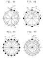
- the four magnets 24 of the second embodiment are provided on the inner peripheral surface of the core pipe P at angular intervals of 67.5 ° around the axis of the pipe P, while the four Hall element sensors 25 are provided at one end of the support shaft 1 at equal angular intervals of 90 ° around the axis of the pipe P.
- the numbers and positions of magnets 24 and sensors 25 are however not limited to those shown in Fig. 7.
- Fig. 8 shows some variations of their numbers and arrangement.
- the Hall element sensor or sensors 25 produces a pulse signal every time the core pipe P rotates 22.5° .
- photosensors may be used to detect the rotation of the core pipe P.
- Such photosensors comprise light emitting diodes and light interceptors and are fixed to one end of the support shaft 1 (outer shaft 1b) as with the Hall elements 25.
- photosensors are mounted on an extension or mounting seats provided on the flange end of the outer shaft 1b, while projections are provided on the core pipe P at angular intervals of 22.5° so as to pass between the light emitting diodes and the light interceptors of the photosensors.
- the numbers of the photosensors and the projections are the same as the Hall element sensors 25 and the magnets 24.
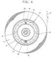
- Fig. 6 is a side view as viewed in the direction of arrow VI-VI of Fig. 2, and mainly shows the position of the displacement detection sensor for the packaging sheet.
- a single proximity switch 26 is provided on the support plate 11.
- Sixteen projections 27 are provided on the flange 15 of the rotatable hollow shaft 1c of the support shaft 1.
- the control unit determines that there is a displacement.
- this operation basically comprises determining the length of sheet forming the paper roll based on the total length 1 of the unwound sheet calculated from the sheet length signal produced by the rotary encoder 32, and the angle ⁇ calculated from the pulse signal from the Hall element sensors 25 as the angle sensors.
- Figs. 9A, 9B for convenience of the description of operation, the number and arrangement of magnets 24 and Hall element sensors 25 are different from those of Fig. 7 and 8. But its basic operation is the same in that one pulse signal is produced for every 22.5 ° rotation.
- the angle sensor when the radius of the paper roll is large, the angle sensor produces fewer pulses while the packaging sheet is unwound by the length 1. As the paper roll radius decreases as shown in Fig. 9B, the number of pulses increases. If the pulse numbers when the paper roll radius is at its maximum and minimum is 3 and 10, respectively, the range of pulse numbers from 3-10 are divided into four stages so as to apply D/C currents that can apply suitable tension corresponding to the respective stages to the motor brake 20 to adjust the braking force.
- the tension level N is adjusted according to the pulse number for a given unwound length of sheet. But the tension level may be determined based on the unwound length of sheet when a predetermined number of pulses have been produced. More detailed description of this method follows:
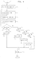
- Figs. 10 and 11 are flowcharts showing the operation of the tension adjusting device. Specifically, Fig. 10 is a flowchart of a special mode to be carried out before the normal mode of the tension adjusting device. Fig. 11 is a flowchart of the normal mode.
- the control unit checks various conditions for the normal packaging operations in the packaging unit so that the normal mode can be carried out smoothly.
- packaging sheet Before the normal packaging operation, packaging sheet has to be correctly set in the packaging unit.
- the packaging sheet is usually set manually by inching.
- the control mode always passes this special mode.
- Step S0 the control unit determines if the current mode is the special mode.
- the special mode starts if any one of the following conditions is met: i.e. the actuation of the end sensor or joint seal, and the detection of inching mode or reverse rotation of the winding length sensor.
- the joint seal is activated while one paper roll has run out and a new roll is being set and spliced to the preceding sheet.
- the inching mode starts by switching on the control unit before the start of all of the operations, and the packaging sheet is manually set in the above-described manner.
- the special mode is necessary because a new, complete paper roll is not always set but there is the possibility that a used roll paper having e.g. half the diameter of a new roll may be set. If the roll set has only half the diameter of a new paper roll, the tension is initially adjusted to an intermediate level smaller than the tension corresponding to the diameter of the new roll.
- Step S0 If the current mode is judged to be the special mode in Step S0, the tension is set at the maximum level in Step SS1, and various sensors (reference sensor, rotation number counter, winding length sensor, core pipe slip sensor) are activated (Step SS2). In this state, the packaging sheet is fed little by little by manual inching, and the signals from the sheet length sensor or rotary encoder 32, and the angle sensors or Hall element sensors 25.
- Step SS5 the control unit calculates the sheet length of the paper roll based on these signals using the above-described formulas to determine whether the roll has the maximum diameter or not, e.g. half the maximum diameter. If this calculation is not possible (NO), Step SS3 is carried out again. If possible, the control unit determines in Step SS7 if the conditions for reentering the special mode are all removed. If they are, the tension is adjusted to a suitable level in Step SS8. Steps SS9 and SS10 are steps for detecting slipping of the core pipe, which will be described later.
- a DC voltage corresponding to maximum tension is set at 25 V if the paper roll has a maximum diameter (new) and at about 20 V if the paper roll diameter is about half the maximum diameter to prevent any abrupt change in tension.
- Steps S3, S4 and S5 the sheet length signal and angle sensor signal are inputted in the same manner as in the special mode to calculate the sheet length of the roll. This calculation is carried out substantially in the above-described manner. If, as a result of calculation, the roll R turns out to be an unused, full-volume roll, the DC voltage is set at 25 V, 16 V, 12 V or 8V in Step S7, S9, S11 or S13 according to the judgment in Steps S6, S8, S10 and S12, in the same way as in the first embodiment.
- Fig. 12 shows the relationship between the above-described winding length and the DC voltage control.
- the control unit determines if the core pipe is slipping in Step S14 based on the signal from the proximity switch 26.
- the switch 26 is provided opposite to the 16 ferromagnetic projections, and produces a pulse signal every time the core pipe rotates 22.5° in exactly the same manner as the Hall element angle sensors 25.
- the angle sensors 25 and 26 are different types, but they may be of the same type.
- the time chart of Fig. 13 shows the relationship between the pulse signals produced by the angle sensors and the rotation angle. As shown, the pulse signals by the slip detection sensor can be obtained synchronously with the pulse signals by the winding length detecting sensor unless the winding condition changes with tension.
- Fig. 13 shows how pulse signals change when such a position shift occurs.
- the slip detection sensor fails to produce pulse signals at positions C and D after the core pipe has made a complete turn. Instead, pulse signals are produced between D and A with some displacement.
- Step S16 After adjusting any position shift of the core pipe P due to sheet tension variation, the control unit checks in Step S16 if paper is still wound on the pipe P based the signal from the end sensor 31. If the sensor 31 has not yet detected the terminal end of the paper, the Step S3 operation is carried out, that is, the sheet tension is controlled according to the winding length of the paper roll by repeating the above calculations.
- the tension control mode ends when the end sensor 31 detects the terminal end of the packaging sheet S. If it is necessary or desired to continue packaging thereafter, the program returns to the special mode to replace the roll R with a new one and connect the sheet ends.
- Steps SS9 and SS10 are shown by chain lines in the flow chart for the special mode, which means that these steps are not essential. If provided, though, their functions are the same as Steps S14, S15 in the slip detection operation in the normal mode.
- the paper roll diameter corresponding to the current winding length of the roll is calculated based on data on the sheet feed length measured by the single sheet length sensor and data on the full winding length of the roll to adjust the sheet tension to an optimum level by controlling the braking force in a stepwise manner based on the paper roll diameter measured.
- the current winding length of the roll is determined based on the change in the signal from one of the sheet length sensor and the angle sensor relative to the signal from the other sensor, and the sheet tension is adjusted by selecting a braking force corresponding to the diameter corresponding to the current winding length.
- the sheet tension is adjusted by selecting a braking force corresponding to the diameter corresponding to the current winding length.
Landscapes
- Engineering & Computer Science (AREA)
- Mechanical Engineering (AREA)
- Controlling Rewinding, Feeding, Winding, Or Abnormalities Of Webs (AREA)
- Registering, Tensioning, Guiding Webs, And Rollers Therefor (AREA)
- Unwinding Webs (AREA)
- Storage Of Web-Like Or Filamentary Materials (AREA)
- Package Closures (AREA)
- Containers And Plastic Fillers For Packaging (AREA)
Abstract
Description
- The present invention relates to a core pipe for a sheet roll.
- One conventional drug packaging device includes a sheet feed unit rotatably supporting a rolled sheet of heat-fusible packaging paper, and a sealing device provided in a feed path through which the packaging sheet is unwound and fed. Upstream of the sealing device, the sheet is folded in half, drugs are supplied, and the sheet is heat-sealed in the width direction and along the edges by the sealing device to seal the drugs.
- When the packaging sheet runs out, a new paper roll is set in the paper feed unit, and the new sheet is unwound and fed. When the sheet is fed, it has to be tensioned uniformly so that the sealing position will not deviate due to inaccurate folding of the sheet. But actually, the tension applied to the sheet changes gradually because the diameter of the paper roll changes gradually as the sheet is unwound.
- Examined Japanese utility model publication discloses a sheet tension adjusting device which can apply uniform tension to the sheet even if the diameter of the sheet roll changes. The sheet tension adjusting device disclosed in this publication has a roll support cylinder on which is detachably mounted a sheet roll. A plurality of roll diameter detection sensors are provided at the side of the sheet roll. Signals from these detection sensors are used to control the electromagnetic force produced by an electromagnetic brake provided in the roll support cylinder so that the baking force decreases stepwise as the roll diameter decreases.
- With this conventional sheet tension adjusting device, the sheet length of the sheet, which changes as the sheet is unwound, is detected stepwise by the roll diameter sensors arranged in the diametric direction of the roll. Thus, when the roll diameter decreases to a point where the detection sensor rank changes, the braking force rank of the electromagnetic brake will fluctuate up and down for every rotation due to deviation of the axis of the core shaft, the weight of the sheet, or winding strain.
- If this happens, the sheet edges cannot be aligned accurately when the sheet is folded in half. Complete packaging is thus impossible. Since the braking force rank changes sharply, the sheet may suffer a laceration in the width direction.
- Light reflecting type detection sensors have a problem in that they are more likely to malfunction. Packaging sheets used for a drug packaging device include semitransparent, or transparent heat-fusible paper and many other kinds of paper. If the end position of such a sheet changes, light is reflected differently, making it impossible to detect the reflected light as a signal. This deteriorates detecting accuracy. Further, it tends to meander under the influence of humidity variations. Detection accuracy may deteriorate due to uneven end faces.
- A thermal printer is usually provided upstream of the position where the sheet is folded in half for printing the packaging sheet. If the sheet vibrates, its printing dots may chip, or the durability of a remainder Further, US-A 4,286,757 discloses a method and an apparatus for controlling the braking system for an unwinder comprising a roll of paper, which is supported at its core by a spindle and comprising braking friction pads which are operated by pressurized air and controlled by a control unit which receives signals from the tachometer-generator outputting a turning signal of the rotating roll and producing a signal to a paper tensioning device for such presenting a desired tension in the following processing stations. However, even this braking control system for an unwinder of the paper roll cannot prevent that the tension of pulling off the paper from the roll fluctuates so wildly that the paper sheet may be stretched unevenly or distorted, thus, making it difficult to present uniform quality for such a sheet.
- Moreover, the device presented by US-A-4,286,757 requires a complex structure which is costly to manufacture and very vulnerable in daily use.
- Accordingly, it is an object of the invention to present a core pipe for a sheet roll which allows sheets to be pulled from the sheet roll, wherein the sheets are neither stretched unevenly nor distorted, so that uniform quality of the sheet can be offered.
- This objective is solved for a core pipe for a sheet roll in an inventive manner in that a core pipe for a sheet roll is provided comprising a hollow core pipe having a predetermined length for winding a sheet therearound, and magnets provided on the inner periphery of said hollow core pipe near one end thereof at angular intervals determined such that the amount and diameter of the sheet roll wound therearound can be calculated by an angle sensor provided on a fixed shaft, said hollow core pipe being rotatable together with a hollow shaft rotatably mounted around said fixed shaft.
- Such a core pipe for a sheet roll, wherein said hollow shaft is inserted through said hollow core pipe, and wherein means for allowing said hollow core pipe to rotate together with said hollow shaft, comprises magnetizable members provided on an end face of said hollow core pipe, and a magnet provided on said hollow shaft.
- The tension in a sheet is adjusted by bringing a braking means into engagement with a roll support cylinder rotatably mounted around a nonrotatably supported support shaft, measuring the length of a sheet being fed from a roll of paper mounted on the roll support cylinder with a sheet length measuring sensor, calculating the winding length of the roll of paper after the sheet has been fed by subtracting the sheet length measured by the sheet length measuring sensor from a prestored maximum sheet length of the roll, calculating the current diameter of the roll based on the winding length of the roll and the thickness of the sheet, and adjusting the tension in the sheet by controlling the braking force of the brake means in a stepwise manner according to the current diameter of the roll.
- The sheet length measuring sensor may be a sheet feed length detection sensor provided in a sheet feed path, or an angle sensor provided on the roll support cylinder for determining the sheet feed length based on the rotation angle of the roll support cylinder.
- The tension in a sheet may also be adjusted by bringing a braking means into engagement with a roll support cylinder rotatably mounted around a nonrotatably supported support shaft, detecting the length of a sheet being fed from a roll of paper mounted on the roll support cylinder with a sheet length measuring sensor, detecting the rotation angle of the roll support cylinder with an angle sensor, calculating the current paper length of the roll based on the sheet length or the rotation angle measured by either sensor, and adjusting the tension in the sheet by controlling the braking force of the brake means in a stepwise manner according to the diameter of the roll corresponding to the current paper length of the roll.
- The sheet length is measured by a single sheet length measuring sensor. Thus, in this method, it is essential that the full sheet length of the paper roll be known. This length is thus stored in a memory, and the current roll length is calculated by subtracting the sheet feed length from the full roll length stored in the memory.
- Such a full roll length does not necessarily have to be an actually measured value but may be approximately calculated based on the roll diameter and the sheet thickness. Such an approximately calculated value is sufficient to adjust the sheet tension because the braking force is adjusted roughly in a stepwise manner according to the changing diameter of the paper roll. Thus, even if the full roll length is not the full length of an intended end product, for example, even if the roll has been half used, it is possible to calculate the current roll length if the full roll length and diameter are known.
- Based on the thus determined current roll length and the sheet thickness, the current roll diameter is calculated. The current roll diameter thus obtained is used to adjust the sheet tension by selecting an optimum brake force in a stepwise manner.
- Signals are detected by the sheet length measuring sensor and the angle sensor. Based on the change in one signal relative to the other, a change in the roll length is directly measured.
- By correlating a predetermined range of change in roll length with a change in the roll diameter beforehand, it is possible to select a stepwise control level of the braking force simply by detecting the change in the roll length. Thus, it is possible to adjust the sheet tension to an optimum level for each stage by controlling the braking force according to the roll diameter.
- A special mode is carried out before a normal mode in which the tension in the sheet is adjusted while the sheet is being fed, the special mode including calculating the paper winding length of the roll based on the signals from the sheet length sensor and the angle sensor in the same manner as in the normal mode by an inching operation in which the sheet is intermittently fed by a predetermined length, and adjusting the braking force to an intermediate level before the start of the normal mode based on the roll diameter calculated from the paper winding length to adjust the tension in the sheet beforehand. Advantages of this arrangement are set forth in the description of the embodiments.
- Any deviation in position between the roll support cylinder and the paper roll detachably mounted on the roll support cylinder is detected in the normal mode and/or the special mode based on an inconsistency between the signal from an angle sensor provided between the roll support cylinder and a support plate of the support shaft for detecting the rotation angle of the roll support cylinder and the signal from the angle sensor provided between the paper roll and the support shaft for detecting the rotation angle of the paper roll.
- Other features and objects of the present invention will become apparent from the following description made with reference to the accompanying drawings, in which:
- Fig. 1 is a partial schematic view of a paper feed unit and a packaging unit of a packaging device;
- Fig. 2 is a vertical sectional view of the paper feed unit with a roll of paper mounted thereon;
- Fig. 3 is a schematic block diagram of a control circuit of a tension adjusting device for a packaging sheet;
- Fig. 4 is a flowchart illustrating the operation of a tension adjusting device of a first embodiment;
- Fig. 5 is a side view of a paper feed unit of a second embodiment as viewed in the direction of arrow V-V of Fig. 2;
- Fig. 6 is a side view of the paper feed unit of the second embodiment as viewed in the direction of the arrow VI-VI of Fig. 2;
- Fig. 7 is a schematic view of an angle sensor of a tension adjusting device of a second embodiment;
- Figs. 8A-8D are schematic views of different type angle sensors;
- Figs. 9A, 9B are views showing basic function of the tension adjusting device of the second embodiment;
- Fig. 10 is a flowchart showing a special operation mode of the tension adjusting device of the second embodiment;
- Fig. 11 is a flowchart showing a normal operation mode thereof;
- Fig. 12 is a graph showing the relationship between the DC voltage applied and the winding length during the special mode; and
- Fig. 13 illustrates how a slip detection sensor detects slipping.
-
- Embodiments of this invention are described with reference to the drawings. Fig. 1 is a schematic diagram of a drug packaging machine showing mainly a paper feed unit and a packaging unit. The paper feed unit has a support shaft 1 on which is rotatably mounted a core pipe P on which is wound a roll R of a drug packaging paper sheet S. The sheet S is unwound from the roll R, and fed through feed rollers 2, 3 to the packaging unit.
- In the packaging unit, the sheet is longitudinally folded in half by a triangular plate 4. Drugs are dropped into the space defined in the folded sheet. The sheet is then heat-sealed widthwise and along both side edges at predetermined intervals by heating rollers 6 with perforators. While the packaging unit includes numerous other parts, only essential parts are shown for simplicity.
- Fig. 2 is a partial vertical section of the paper feed unit in which the roll paper R and the core pipe P are set. As shown, the support shaft 1 comprises a center shaft la having one end thereof fixed to a support plate 11 by a nut, an outer shaft 1b integrally mounted around the center shaft 1a, and a hollow shaft 1c rotatably mounted on the outer shaft 1b through bearings 12 provided near both ends of the outer shaft 1b.
- The center shaft la has a shaft head 13 at one end. The outer shaft 1b has a flange 14 at the same one end. The hollow shaft 1c has a flange 15 at the other end. The core pipe P and the roll paper R, mounted on the hollow shaft 1c, are rotatable relative to the support shaft 1. A plurality of magnets 16 are provided on the inner peripheral surface of the flange 15 at suitable intervals. Ferromagnetic (iron) members 17 are provided along the circumference of an end face of the core pipe P. The magnets 16 attract the ferromagnetic member 17 to detachably mount the core pipe P and the roll paper R on the hollow shaft 1c.
- Packaging sheet S unwound from the roll paper R is suitably tensioned by a motor brake 20 engaging the hollow shaft 1c. The motor brake 20, mounted on the support plate 11, is connected to a gear unit 21 through a transmission belt, not shown. The gear unit 21 has an output shaft on which is mounted a pinion 22 in mesh with a large gear 23 provided on the outer peripheral surface of the flange 15. Thus, by activating the motor brake 20, braking force is applied to the hollow shaft 1c.
- The motor brake 20 is a small AC motor powered by a DC voltage. As will be described below, braking force is variable in four stages according to the tension in the packaging sheet S being unwound by changing the DC voltage applied in four stages.
- Magnets 24, Hall element sensors 25, a proximity switch 26 and projections 27 are described in the second embodiment.
- Fig. 3 schematically shows a brake circuit for controlling various parts of the device for feeding packaging sheet from the paper feed unit and packaging drugs. Its control unit 30 receives signals from an end sensor 31, those from a rotary encoder 32 provided near the feed rollers 3, and those from a revolving speed counter 33 mounted on the output shaft of a motor 6a coupled to the shaft of one of the heating rollers 6, and produces, based on one of the above signals, outputs for activating the motor brake 20 or the motor 6a. Numeral 34 indicates an input unit for inputting external data.
- Drugs are packaged while adjusting the tension in the packaging sheet with the sheet tension adjusting device of the first embodiment.
- In the first embodiment, the maximum diameter dmax and the minimum diameter do of the roll paper R to be set in the paper feed unit are known beforehand. Braking force produced by the motor brake 20 is varied in four stages according to the signal from the rotary encoder 32 to apply suitable tension to the sheet by adjusting the braking force according to the changing diameter of the paper roll R.
- The roll paper R shown has a maximum diameter dmax= 160 mm, minimum diameter d0 ≒ 64 mm, and sheet thickness γ = 30 µm. In this case, braking force produced by the motor brake is varied every time the diameter of the paper roll R decreases (160 - 64)/4 = 24 mm.
- The length of the sheet forming a roll R of a given diameter is given by the following formula:(wherein n is the number of turns)

- The diameter of the roll R is given as follows:
- From Formula (1), the length Lmax of the sheet forming the roll R when the roll diameter is maximum is:
- From Formula (2), dmax = 64 + 2 X 30n × 10-3 = 160 (mm)
- Thus,
- Hence,

- Now, let the diameter range of the roll paper divide into four stages N = 1 (largest), 2 (second largest), 3 (third largest) and 4 (smallest). The maximum sheet length of the roll in each stage is given by the following formulas:
- where N = 1, Lmax = 562,688 (m), (n = 1600, dmax = 160)
- where N = 2, Lmax = 376,800 (m), (n = 1200, dmax = 136)
- where N = 3, Lmax = 221,056 (m), (n = 800, dmax = 112)
- where N = 4, Lmax = 95,456 (m), (n = 400, dmax = 88)
-
- The control unit 30 receives the signal from the rotary encoder 32 to measure the length of packaging sheet S to the feed rollers 3 and determines in which one of the stages 1-4 the diameter of the roll R is. Then, the control unit determines the DC voltage to be applied to the motor brake 20 so that an equal tension is applied to the sheet for all the stages 1-4. For example, the DC voltage is determined as follows:
- where N = 1, V = 25V
- where N = 2, V = 16V
- where N = 3, V = 12V
- where N = 4, V = 8V
-
- Referring now to the flowchart of Fig. 4, this method is described more specifically.
- First, as shown in Fig. 1, the packaging sheet S is slightly unwound from the paper roll R to a point at least downstream of the heating rolls 6 and sandwiched between the heating rolls 6 so that the sheet can be heat-sealed by the heating rolls 6.
- In this state, the control unit is started. In Step S1, data on dimensions of the paper roll R is entered through the input unit 34. Such data, that is, data on the completely wound paper roll R may be stored in the input unit 34 beforehand and fed to the control unit when a signal on an end product is entered. Otherwise, necessary data may be entered through a keyboard every time such data are needed. The latter method is advantageous when a half-used paper roll R is reset. When these data are entered, the control unit 30 begins to control the computation and feed the packaging sheet S. In Step S2, a maximum DC voltage is applied to feed the packaging sheet S with its tension kept at the maximum.
- In Step S3, a signal on the sheet length data is read. In this embodiment, this signal is the signal from the rotary encoder 32 and is inputted for every processing cycle in each of the steps described below.
- In Step S4, based on the input signal, the control unit calculates the number by which the turns of the paper roll has decreased from the maximum diameter until the above signal is inputted, and based on this number, calculates the remaining sheet length of the paper roll and its diameter at this moment, using the formulas (1) and (2). In Step S5, based on the thus calculated remaining sheet length of the paper roll, the tension level is determined.
- That is, in Step S5, the control unit 30 determines, based on the remaining sheet length of the roll, in which one of the stages 1-4 the diameter of the paper roll R is. If the diameter of the roll is in stage N = 1, a predetermined DC voltage for tensioning the sheet S to the maximum level is applied to the motor brake 20 in Step S6.
- If N ≠ 1, the control unit determines if N = 2 in Step S7.
- If N = 2, a DC voltage of 16 V is applied to the motor brake 20 in Step S8. If N ≠ 2, the control unit determines if N = 3 in Step S9. If it is, a DC voltage 12 V is applied in Step S10. If not, the control unit determines if N = 4 in Step S11. If it is, a DC voltage 8 V is applied in Step S12.
- The above operation is carried out for every cycle in the processing loop. If N≠ 4 in Step S11, which means that the packaging sheet S has been unwound completely, the control unit stops the feed of sheet S after confirming the signal from the end sensor 31 in Step 13. This completes the entire contorol.
- In this embodiment, the signal from the rotary encoder 32 is used to measure the sheet length and control the motor brake 20 based on the sheet length. But instead, the sheet length may be measured by use of signal from a sensor provided on the support shaft 1 of the paper feed unit for detecting the rotary angle of the paper roll R. This sensor is used in the second embodiment.
- In the first embodiment, it is assumed that the sheet has a thickness of 30 µm. But actually, while the sheet is being fed, it is stretched due to the tension applied to the sheet. Thus, the sheet thickness is usually smaller while being fed than while in a stationary state. Thus, the sheet thickness while the sheet is being fed should be determined by reducing the sheet thickness in a stationary state by a certain rate which is estimated based on average elongation of the sheet while being fed.
- Fig. 5 and the subsequent figures show the second embodiment, which is of basically the same construction as the first embodiment but includes additional elements so that the sheet tension can be controlled with higher accuracy.
- The paper feed unit and the packaging unit of this embodiment are those shown in Figs. 1-3. This embodiment differs from the first embodiment in that, as shown in Fig. 3, the control unit 30 receives the signals from a rotary angle sensor assembly comprising four magnets 24 on the core pipe P and four Hall element sensors 25, and a sheet displacement sensor comprising a proximity switch 26 and projections 27 (see Figs. 2 and 5).
- Specifically, the control unit accurately calculates the length of the sheet S unwound from the paper roll R based on the sheet length sensor signal of the first embodiment and the signal from the rotation angle sensor, and adjusts the braking force corresponding to the variation in diameter of the roll R to adjust the tension applied to the sheet.
- As shown in Fig. 7, the four magnets 24 of the second embodiment are provided on the inner peripheral surface of the core pipe P at angular intervals of 67.5 ° around the axis of the pipe P, while the four Hall element sensors 25 are provided at one end of the support shaft 1 at equal angular intervals of 90 ° around the axis of the pipe P.
- The numbers and positions of magnets 24 and sensors 25 are however not limited to those shown in Fig. 7. Fig. 8 shows some variations of their numbers and arrangement. In any variation, the Hall element sensor or sensors 25 produces a pulse signal every time the core pipe P rotates 22.5° .
- Also, instead of the combination of magnets 24 and Hall elements 25, photosensors may be used to detect the rotation of the core pipe P. Such photosensors comprise light emitting diodes and light interceptors and are fixed to one end of the support shaft 1 (outer shaft 1b) as with the Hall elements 25.
- More particularly, such photosensors are mounted on an extension or mounting seats provided on the flange end of the outer shaft 1b, while projections are provided on the core pipe P at angular intervals of 22.5° so as to pass between the light emitting diodes and the light interceptors of the photosensors. The numbers of the photosensors and the projections are the same as the Hall element sensors 25 and the magnets 24.
- Fig. 6 is a side view as viewed in the direction of arrow VI-VI of Fig. 2, and mainly shows the position of the displacement detection sensor for the packaging sheet. In this example, a single proximity switch 26 is provided on the support plate 11. Sixteen projections 27 are provided on the flange 15 of the rotatable hollow shaft 1c of the support shaft 1.
- If there is a difference in pitch between the rotation angle sensor signal detected by the Hall element sensors 25 and the signal detected by the displacement detection sensor, the control unit determines that there is a displacement.
- Now the operation of the second embodiment is described. As shown in Figs. 9A, 9B, this operation basically comprises determining the length of sheet forming the paper roll based on the total length 1 of the unwound sheet calculated from the sheet length signal produced by the rotary encoder 32, and the angle calculated from the pulse signal from the Hall element sensors 25 as the angle sensors.
- In Figs. 9A, 9B, for convenience of the description of operation, the number and arrangement of magnets 24 and Hall element sensors 25 are different from those of Fig. 7 and 8. But its basic operation is the same in that one pulse signal is produced for every 22.5 ° rotation.
- As shown Fig. 9A, when the radius of the paper roll is large, the angle sensor produces fewer pulses while the packaging sheet is unwound by the length 1. As the paper roll radius decreases as shown in Fig. 9B, the number of pulses increases. If the pulse numbers when the paper roll radius is at its maximum and minimum is 3 and 10, respectively, the range of pulse numbers from 3-10 are divided into four stages so as to apply D/C currents that can apply suitable tension corresponding to the respective stages to the motor brake 20 to adjust the braking force.
- There is the following relationship between the above tension level N = 1-4 and the pulse number. Provide the maximum and minimum diameters of the paper roll R are 160 mm and 64 mm, respectively, the length of the sheet unwound from the roll when the roll diameter is maximum will be π × 160 mm. Since the angle sensor 25 produces one pulse signal for every 22.5° rotation (16 pulses for every full turn), the sheet is unwound by π × 160/16 = 314 m/m. For the unwound length of 3140 m/m, the pulse number will be 10.
- When the roll diameter is minimum, there is the following relation between the length of sheet unwound and the pulse number. That is, since π × 64/16 = 129.5 m/m, for the unwound length of 3140 m/m, the pulse number will be 3140/1295 × 10 = 24.2.
- The pulse number and the DC voltage for every tension level N are determined as follows:
Tension Level N Pulse Number DC Voltage N = 1 10-13 25V N = 2 14-17 16V N = 3 18-21 12V N = 4 22-24.2 8V - In the above description, the tension level N is adjusted according to the pulse number for a given unwound length of sheet. But the tension level may be determined based on the unwound length of sheet when a predetermined number of pulses have been produced. More detailed description of this method follows:
- Figs. 10 and 11 are flowcharts showing the operation of the tension adjusting device. Specifically, Fig. 10 is a flowchart of a special mode to be carried out before the normal mode of the tension adjusting device. Fig. 11 is a flowchart of the normal mode.
- In the special mode shown in Fig. 10, the control unit checks various conditions for the normal packaging operations in the packaging unit so that the normal mode can be carried out smoothly. Before the normal packaging operation, packaging sheet has to be correctly set in the packaging unit. The packaging sheet is usually set manually by inching. The control mode always passes this special mode.
- In Step S0, the control unit determines if the current mode is the special mode. The special mode starts if any one of the following conditions is met: i.e. the actuation of the end sensor or joint seal, and the detection of inching mode or reverse rotation of the winding length sensor. The joint seal is activated while one paper roll has run out and a new roll is being set and spliced to the preceding sheet.
- The inching mode starts by switching on the control unit before the start of all of the operations, and the packaging sheet is manually set in the above-described manner.
- The special mode is necessary because a new, complete paper roll is not always set but there is the possibility that a used roll paper having e.g. half the diameter of a new roll may be set. If the roll set has only half the diameter of a new paper roll, the tension is initially adjusted to an intermediate level smaller than the tension corresponding to the diameter of the new roll.
- If the current mode is judged to be the special mode in Step S0, the tension is set at the maximum level in Step SS1, and various sensors (reference sensor, rotation number counter, winding length sensor, core pipe slip sensor) are activated (Step SS2). In this state, the packaging sheet is fed little by little by manual inching, and the signals from the sheet length sensor or rotary encoder 32, and the angle sensors or Hall element sensors 25.
- In Step SS5, the control unit calculates the sheet length of the paper roll based on these signals using the above-described formulas to determine whether the roll has the maximum diameter or not, e.g. half the maximum diameter. If this calculation is not possible (NO), Step SS3 is carried out again. If possible, the control unit determines in Step SS7 if the conditions for reentering the special mode are all removed. If they are, the tension is adjusted to a suitable level in Step SS8. Steps SS9 and SS10 are steps for detecting slipping of the core pipe, which will be described later.
- During tension adjustment in Step SS8, a DC voltage corresponding to maximum tension is set at 25 V if the paper roll has a maximum diameter (new) and at about 20 V if the paper roll diameter is about half the maximum diameter to prevent any abrupt change in tension.
- When the tension has been adjusted to a suitable level, the program returns to Step S0 to determine whether or not to carry out the special mode operation again. This time, the program proceeds to the normal mode [A].
- In the normal mode shown in Fig. 11, an inching mode switch is manually changed over, and then in Step S1, the previously set data is read out, and the various sensors are kept turned on (S2). By this time, the normal operation of the packaging unit has started. At the start of the normal operation, the tension is controlled to the DC current value suitably set in the special mode.
- Then in Steps S3, S4 and S5, the sheet length signal and angle sensor signal are inputted in the same manner as in the special mode to calculate the sheet length of the roll. This calculation is carried out substantially in the above-described manner. If, as a result of calculation, the roll R turns out to be an unused, full-volume roll, the DC voltage is set at 25 V, 16 V, 12 V or 8V in Step S7, S9, S11 or S13 according to the judgment in Steps S6, S8, S10 and S12, in the same way as in the first embodiment. Fig. 12 shows the relationship between the above-described winding length and the DC voltage control.
- After the tension control has been carried out via any of the abovementioned routes, the control unit determines if the core pipe is slipping in Step S14 based on the signal from the proximity switch 26. As shown in Fig. 6, the switch 26 is provided opposite to the 16 ferromagnetic projections, and produces a pulse signal every time the core pipe rotates 22.5° in exactly the same manner as the Hall element angle sensors 25.
- In the embodiments, the angle sensors 25 and 26 are different types, but they may be of the same type. The time chart of Fig. 13 shows the relationship between the pulse signals produced by the angle sensors and the rotation angle. As shown, the pulse signals by the slip detection sensor can be obtained synchronously with the pulse signals by the winding length detecting sensor unless the winding condition changes with tension.
- But if the rotation resistance of the motor brake 20 produced by each of the above-described DC voltages is inappropriate, for example, if the tension is too large at the tension level N = 2, the paper roll R will rotate strongly together with the core pipe P. This may cause a shift in the position where the ferromatnetic members 17 are attracted to the magnets 16. If this happens, although the Hall element sensors 25 keep producing pulse signals at regular angular intervals of 22.5° , the proximity switch 26 may produce two pulse signals simultaneously and fails to produce a signal when the core pipe rotates another 22.5° .
- Fig. 13 shows how pulse signals change when such a position shift occurs. As shown, the slip detection sensor fails to produce pulse signals at positions C and D after the core pipe has made a complete turn. Instead, pulse signals are produced between D and A with some displacement.
- In such a case, the control unit can determine that the slip detection sensor has failed to produce a pulse signal at position C by referring to the signal from the winding length detection sensor. If, for example, the DC current of 16 V is too high at the level N = 2, so that the tension is too high, the voltage may be reduced to 14 V to adjust the tension to a suitable level. With this voltage adjustment, a pulse signal can be produced at any desired position after position D.
- After adjusting any position shift of the core pipe P due to sheet tension variation, the control unit checks in Step S16 if paper is still wound on the pipe P based the signal from the end sensor 31. If the sensor 31 has not yet detected the terminal end of the paper, the Step S3 operation is carried out, that is, the sheet tension is controlled according to the winding length of the paper roll by repeating the above calculations.
- The tension control mode ends when the end sensor 31 detects the terminal end of the packaging sheet S. If it is necessary or desired to continue packaging thereafter, the program returns to the special mode to replace the roll R with a new one and connect the sheet ends.
- Steps SS9 and SS10 are shown by chain lines in the flow chart for the special mode, which means that these steps are not essential. If provided, though, their functions are the same as Steps S14, S15 in the slip detection operation in the normal mode.
- The above description has been made on the assumption that the paper roll R is a full-volume roll. If a roll about half the maximum diameter is set in the paper feed unit, after the tension has been adjusted in the special mode to a level slightly larger than the tension during the normal mode when the full-volume roll is unwound to about half the maximum diameter, the normal mode is started. It is thus possible to smoothly start the normal mode without the possibility of an abrupt rise in tension.
- As described above, according to the present inventions, the paper roll diameter corresponding to the current winding length of the roll is calculated based on data on the sheet feed length measured by the single sheet length sensor and data on the full winding length of the roll to adjust the sheet tension to an optimum level by controlling the braking force in a stepwise manner based on the paper roll diameter measured. Thus, it is possible to adjust the sheet tension to an optimum level by selecting the braking force in a stepwise manner corresponding to the roll diameter corresponding to the gradually decreasing winding length of the roll, unless the winding length of the roll begins to increase. It is thus possible to smoothly adjust the sheet tension without the possibility of abrupt tension fluctuations due to sudden fluctuations in braking force when the roll diameter changes slightly.
- According to another aspect of the present invention, the current winding length of the roll is determined based on the change in the signal from one of the sheet length sensor and the angle sensor relative to the signal from the other sensor, and the sheet tension is adjusted by selecting a braking force corresponding to the diameter corresponding to the current winding length. In this arrangement, the even if data on the full winding length is not known, it is possible to adjust the sheet tension by selecting a braking force corresponding to the roll diameter corresponding to the current winding length determined based on the measurement data. Thus, it is possible to smoothly adjust the sheet tension without the possibility of abrupt change in tension, in the same manner as in the first invention.
Claims (2)
- A core pipe for a sheet roll (R) comprising a hollow core pipe (P) having a predetermined length for winding a sheet (S) therearound, and magnets (16) provided on the inner periphery of said hollow core pipe (P) near one end thereof at angular intervals determined such that the amount and diameter of the sheet roll (R) wound therearound can be calculated by an angle sensor (24, 25) provided on a fixed shaft (1b), said hollow core pipe (P) being rotatable together with a hollow shaft (1c) rotatably mounted around said fixed shaft (1b).
- A core pipe for a sheet roll as claimed in claim 1, wherein said hollow shaft (1 c) is inserted through said hollow core pipe (P), and wherein means for allowing said hollow core pipe (P) to rotate together with said hollow shaft (15) comprises magnetizable members (17) provided on an end face of said hollow core pipe (P), and a magnet (16) provided on said hollow shaft (1c).
Applications Claiming Priority (3)
| Application Number | Priority Date | Filing Date | Title |
|---|---|---|---|
| JP25049296 | 1996-09-20 | ||
| JP25049296 | 1996-09-20 | ||
| EP97115567A EP0831048B1 (en) | 1996-09-20 | 1997-09-08 | Device for adjusting tension applied to web |
Related Parent Applications (1)
| Application Number | Title | Priority Date | Filing Date |
|---|---|---|---|
| EP97115567A Division EP0831048B1 (en) | 1996-09-20 | 1997-09-08 | Device for adjusting tension applied to web |
Publications (3)
| Publication Number | Publication Date |
|---|---|
| EP1052211A2 true EP1052211A2 (en) | 2000-11-15 |
| EP1052211A3 EP1052211A3 (en) | 2001-04-11 |
| EP1052211B1 EP1052211B1 (en) | 2003-04-16 |
Family
ID=17208681
Family Applications (3)
| Application Number | Title | Priority Date | Filing Date |
|---|---|---|---|
| EP00116709A Expired - Lifetime EP1052211B1 (en) | 1996-09-20 | 1997-09-08 | A core pipe for a sheet roll |
| EP97115567A Expired - Lifetime EP0831048B1 (en) | 1996-09-20 | 1997-09-08 | Device for adjusting tension applied to web |
| EP00109244A Expired - Lifetime EP1029818B1 (en) | 1996-09-20 | 1997-09-08 | Roll of sheet for use with a drug packaging device |
Family Applications After (2)
| Application Number | Title | Priority Date | Filing Date |
|---|---|---|---|
| EP97115567A Expired - Lifetime EP0831048B1 (en) | 1996-09-20 | 1997-09-08 | Device for adjusting tension applied to web |
| EP00109244A Expired - Lifetime EP1029818B1 (en) | 1996-09-20 | 1997-09-08 | Roll of sheet for use with a drug packaging device |
Country Status (9)
| Country | Link |
|---|---|
| EP (3) | EP1052211B1 (en) |
| KR (1) | KR100310966B1 (en) |
| CN (3) | CN1162317C (en) |
| CA (3) | CA2316140C (en) |
| DE (3) | DE69714535T2 (en) |
| DK (3) | DK0831048T3 (en) |
| ES (3) | ES2179986T3 (en) |
| PT (3) | PT1052211E (en) |
| TW (1) | TW348165B (en) |
Families Citing this family (44)
| Publication number | Priority date | Publication date | Assignee | Title |
|---|---|---|---|---|
| DE19838545A1 (en) * | 1998-08-25 | 2000-03-02 | Focke & Co | Method and device for recognizing print marks |
| US6247293B1 (en) * | 1998-11-03 | 2001-06-19 | Klockner Bartelt, Inc. | Modular packaging machine with web tension control |
| US6195967B1 (en) * | 1998-11-03 | 2001-03-06 | Klockner Bartelt, Inc. | Packaging machine having continuous and intermittent modes |
| US6272815B1 (en) * | 1998-11-03 | 2001-08-14 | Klockner-Bartelt, Inc. | Servo-controlled pouch making apparatus |
| DE19936006A1 (en) * | 1999-08-04 | 2001-03-01 | Honeywell Ag | Device and method for determining the position of material sections in wound material webs |
| JP3964730B2 (en) * | 2002-05-02 | 2007-08-22 | 株式会社湯山製作所 | Drug packaging device |
| DE10324356A1 (en) * | 2003-05-27 | 2005-01-05 | Kunststoff-Spritzgußwerk Ing. Klaus Burk GmbH | mandrel |
| CN1299959C (en) * | 2004-07-22 | 2007-02-14 | 安庆市恒昌机械制造有限责任公司 | Constant tension jointing device for strip-shaped non-woven fabric substrate |
| JP2006272883A (en) * | 2005-03-30 | 2006-10-12 | Nissha Printing Co Ltd | Apparatus and method of transfer molding |
| JP4396573B2 (en) * | 2005-05-10 | 2010-01-13 | セイコーエプソン株式会社 | Roll paper transport device and printing device |
| JP5510781B2 (en) | 2009-09-15 | 2014-06-04 | 株式会社リコー | Paper feeding device and image forming apparatus |
| CN102806572B (en) * | 2011-06-02 | 2014-09-10 | 北新集团建材股份有限公司 | Paper cutting device capable of automatically adjusting tension and automatically guiding paper |
| CN109592135B (en) * | 2012-10-03 | 2021-06-01 | 株式会社汤山制作所 | Drug inspection system, winding device, feeding device, and holder |
| KR101404028B1 (en) * | 2013-02-04 | 2014-06-27 | 한국철도기술연구원 | Release detection apparatus for bolt and nut using hall sensor |
| CN103086180B (en) * | 2013-02-19 | 2016-06-01 | 苏州东昇机电科技有限公司 | A kind of unreeling machine and control flexible materials put the method for volume |
| KR101456993B1 (en) * | 2013-03-18 | 2014-11-04 | 주식회사 인포피아 | Real-time tension control system for medicine packing paper |
| CN103420199B (en) * | 2013-07-24 | 2016-06-08 | 宁波欣达印刷机器有限公司 | Combined gravure printing machine auxiliary material collecting device |
| CN103587998B (en) * | 2013-11-05 | 2016-06-15 | 成都瑞克西自动化技术有限公司 | Tenslator |
| CN104562514B (en) * | 2015-01-13 | 2016-08-17 | 海宁华讯纺织有限公司 | The charging apparatus of cloth in dyeing machine |
| GB201513541D0 (en) * | 2015-07-31 | 2015-09-16 | Videojet Technologies Inc | Tape drive and associated spool |
| KR102452199B1 (en) * | 2015-12-21 | 2022-10-06 | 엘지디스플레이 주식회사 | Rollable display apparatus and apparatus for inspection the same |
| CN105645150B (en) * | 2016-03-23 | 2018-03-06 | 长园长通新材料股份有限公司 | A kind of full-automatic clot packaging facilities of pyrocondensation sheet material |
| CN105947267B (en) * | 2016-04-29 | 2018-07-31 | 青岛三维海容机电有限公司 | A kind of powder casing device |
| CN105855323A (en) * | 2016-06-02 | 2016-08-17 | 新昌县羽林街道上大轴承厂 | Metal plate uncoiling machine special for machining |
| EP3392173B1 (en) * | 2017-04-20 | 2020-12-23 | Tetra Laval Holdings & Finance S.A. | Wrapping of food products |
| EP3609715B1 (en) * | 2017-07-28 | 2024-04-24 | Hewlett-Packard Development Company, L.P. | Determinations of lengths of web medias |
| CN108059024A (en) * | 2017-12-22 | 2018-05-22 | 温州市华龙印刷机械有限公司 | A kind of unwinding tension automatic control structure |
| DE102017131417A1 (en) | 2017-12-29 | 2019-07-04 | Weber Maschinenbau Gmbh Breidenbach | Device for packaging objects |
| CN108975094A (en) * | 2018-06-22 | 2018-12-11 | 郑州默尔电子信息技术有限公司 | A kind of adjustable cable winder |
| CN109911671A (en) * | 2019-02-28 | 2019-06-21 | 深圳市汇美新科技有限公司 | A kind of equidistant winding control method and rolling-up mechanism |
| CN112158663A (en) * | 2019-03-06 | 2021-01-01 | 徐德本 | Indicating lamp parallel connection indicating type winding mechanism |
| JP7298867B2 (en) | 2019-03-08 | 2023-06-27 | 株式会社タカゾノ | Combination of wound body and packaging device |
| CN110127461B (en) * | 2019-05-28 | 2022-04-05 | 肇庆学院 | Agricultural wire winding and unwinding device |
| CN110296726A (en) * | 2019-06-27 | 2019-10-01 | 武汉市海维鑫科技有限公司 | A kind of encoder apparatus |
| CN110342296A (en) * | 2019-08-16 | 2019-10-18 | 苏州金纬片板膜智能装备有限公司 | Retractable volume all-in-one machine for composite sheet |
| CN111196057B (en) * | 2020-03-15 | 2021-05-07 | 江西伊发电力科技股份有限公司 | Hard board paper tube forming machine for transformer |
| CN111671348B (en) * | 2020-05-13 | 2022-07-05 | 北京小趣智品科技有限公司 | Paper data processing method and system |
| CN114312055B (en) * | 2020-09-30 | 2023-12-29 | 上海商米科技集团股份有限公司 | Automatic paper width type detection method and system |
| CN113002143B (en) * | 2021-02-26 | 2022-08-26 | 重庆市金利药包材料有限公司 | Double-sided printing device for packaging bag production |
| CN113184599B (en) * | 2021-04-30 | 2023-07-28 | 杭州丙甲科技有限公司 | Device for unwinding sheet material into packaging material and tension adjusting method thereof |
| CN114030666B (en) * | 2021-11-08 | 2022-12-27 | 重庆市轩瑞食品有限公司 | Processing method of sauced chicken feet and full-automatic sealing and packaging machine thereof |
| CN114803723A (en) * | 2022-04-15 | 2022-07-29 | 哈工大机器人(合肥)国际创新研究院 | Cable winding and unwinding devices |
| CN114935321B (en) * | 2022-05-11 | 2023-06-16 | 江汉大学 | High-precision gate opening and closing measuring method |
| CN115285398B (en) * | 2022-09-28 | 2022-12-13 | 常州隆利医疗科技有限公司 | Intelligent automatic packaging machine for disposable sterile syringe |
Citations (3)
| Publication number | Priority date | Publication date | Assignee | Title |
|---|---|---|---|---|
| EP0401036A1 (en) * | 1989-06-02 | 1990-12-05 | Sony Corporation | Printing machine for thermal print roll paper |
| DE4300403A1 (en) * | 1993-01-09 | 1994-07-14 | Esselte Meto Int Gmbh | Motorised drive for web with contactless electric sensor of movement |
| EP0875482A1 (en) * | 1997-04-29 | 1998-11-04 | Hewlett-Packard Company | Encoding and reading information on a roll of media |
Family Cites Families (12)
| Publication number | Priority date | Publication date | Assignee | Title |
|---|---|---|---|---|
| US3396919A (en) * | 1966-03-01 | 1968-08-13 | Gen Cable Corp | Magnetic bobbin holding device |
| US3898436A (en) * | 1974-03-22 | 1975-08-05 | Armco Steel Corp | Coil diameter control system |
| US4199118A (en) * | 1979-01-10 | 1980-04-22 | The Black Clawson Company | Method and apparatus for controlling the braking system for an unwinder |
| US4286757A (en) * | 1980-04-03 | 1981-09-01 | The Black Clawson Company | Method and apparatus for controlling the braking system for an unwinder |
| US4357086A (en) * | 1980-08-18 | 1982-11-02 | Nippon Kogaku K.K. | Focus detecting optical device of a single lens reflex camera |
| US4477398A (en) * | 1982-07-06 | 1984-10-16 | Eastman Kodak Company | Yarn monitoring process |
| JPS61211263A (en) * | 1985-03-13 | 1986-09-19 | Toshiba Corp | Driving device of winding device |
| JP3275921B2 (en) * | 1992-06-11 | 2002-04-22 | 株式会社安川電機 | Detection method of initial diameter of unwinding coil |
| JP3357410B2 (en) * | 1993-01-22 | 2002-12-16 | 日本たばこ産業株式会社 | Strip feeder for tobacco manufacturing machine |
| JPH06239428A (en) * | 1993-02-10 | 1994-08-30 | Rohm Co Ltd | Chute for electronic part |
| US5503349A (en) * | 1993-07-09 | 1996-04-02 | Certek Corporation | Roll-stand brake |
| US5481855A (en) * | 1994-09-27 | 1996-01-09 | Yuyama; Shoji | Tablet packing device and method for controlling the same |
-
1997
- 1997-08-29 CA CA002316140A patent/CA2316140C/en not_active Expired - Fee Related
- 1997-08-29 CA CA002316091A patent/CA2316091A1/en not_active Abandoned
- 1997-08-29 CA CA002214597A patent/CA2214597C/en not_active Expired - Lifetime
- 1997-09-08 PT PT00116709T patent/PT1052211E/en unknown
- 1997-09-08 PT PT00109244T patent/PT1029818E/en unknown
- 1997-09-08 PT PT97115567T patent/PT831048E/en unknown
- 1997-09-08 DE DE69714535T patent/DE69714535T2/en not_active Expired - Lifetime
- 1997-09-08 EP EP00116709A patent/EP1052211B1/en not_active Expired - Lifetime
- 1997-09-08 ES ES97115567T patent/ES2179986T3/en not_active Expired - Lifetime
- 1997-09-08 DK DK97115567T patent/DK0831048T3/en active
- 1997-09-08 EP EP97115567A patent/EP0831048B1/en not_active Expired - Lifetime
- 1997-09-08 EP EP00109244A patent/EP1029818B1/en not_active Expired - Lifetime
- 1997-09-08 DK DK00109244T patent/DK1029818T3/en active
- 1997-09-08 ES ES00109244T patent/ES2195816T3/en not_active Expired - Lifetime
- 1997-09-08 DK DK00116709T patent/DK1052211T3/en active
- 1997-09-08 ES ES00116709T patent/ES2193914T3/en not_active Expired - Lifetime
- 1997-09-08 DE DE69721591T patent/DE69721591T2/en not_active Expired - Lifetime
- 1997-09-08 DE DE69721084T patent/DE69721084T2/en not_active Expired - Lifetime
- 1997-09-12 TW TW086113372A patent/TW348165B/en not_active IP Right Cessation
- 1997-09-20 KR KR1019970047867A patent/KR100310966B1/en not_active IP Right Cessation
- 1997-09-22 CN CNB011197374A patent/CN1162317C/en not_active Expired - Fee Related
- 1997-09-22 CN CN97119204A patent/CN1077080C/en not_active Expired - Fee Related
- 1997-09-22 CN CNB001065300A patent/CN1165472C/en not_active Expired - Fee Related
Patent Citations (3)
| Publication number | Priority date | Publication date | Assignee | Title |
|---|---|---|---|---|
| EP0401036A1 (en) * | 1989-06-02 | 1990-12-05 | Sony Corporation | Printing machine for thermal print roll paper |
| DE4300403A1 (en) * | 1993-01-09 | 1994-07-14 | Esselte Meto Int Gmbh | Motorised drive for web with contactless electric sensor of movement |
| EP0875482A1 (en) * | 1997-04-29 | 1998-11-04 | Hewlett-Packard Company | Encoding and reading information on a roll of media |
Also Published As
Similar Documents
| Publication | Publication Date | Title |
|---|---|---|
| EP0831048B1 (en) | Device for adjusting tension applied to web | |
| US6059222A (en) | Method of adjusting tension applied to sheet, and device for the same | |
| CA2246982C (en) | Device for adjusting tension applied to sheet | |
| JP2909450B2 (en) | Seat tension adjustment device | |
| US6533207B2 (en) | Method and arrangement for producing a roll from printed products | |
| JP4302818B2 (en) | Drug packaging device | |
| KR100528642B1 (en) | Seat tension adjusting device | |
| JP3042041U (en) | Seat tension adjustment device | |
| JPH07228404A (en) | Winding method for sheet-like object and its device | |
| KR101210697B1 (en) | Driving means for position control apparatus using ac motor | |
| JPH10119910A (en) | Film transfer device for horizontal bag-making, filling machine | |
| KR20160024579A (en) | Driving apparatus for roll | |
| JPS63202551A (en) | Web taking-up device in hybrid type high speed printing machine | |
| JPH07165208A (en) | Stretch-packing apparatus |
Legal Events
| Date | Code | Title | Description |
|---|---|---|---|
| PUAI | Public reference made under article 153(3) epc to a published international application that has entered the european phase |
Free format text: ORIGINAL CODE: 0009012 |
|
| AC | Divisional application: reference to earlier application |
Ref document number: 831048 Country of ref document: EP |
|
| AK | Designated contracting states |
Kind code of ref document: A2 Designated state(s): BE DE DK ES FR GB GR IE IT NL PT |
|
| PUAL | Search report despatched |
Free format text: ORIGINAL CODE: 0009013 |
|
| RIC1 | Information provided on ipc code assigned before grant |
Free format text: 7B 65H 75/10 A, 7B 65H 75/18 B |
|
| AK | Designated contracting states |
Kind code of ref document: A3 Designated state(s): BE DE DK ES FR GB GR IE IT NL PT |
|
| 17P | Request for examination filed |
Effective date: 20010606 |
|
| AKX | Designation fees paid |
Free format text: BE DE DK ES FR GB GR IE IT NL PT |
|
| 17Q | First examination report despatched |
Effective date: 20011220 |
|
| GRAG | Despatch of communication of intention to grant |
Free format text: ORIGINAL CODE: EPIDOS AGRA |
|
| GRAG | Despatch of communication of intention to grant |
Free format text: ORIGINAL CODE: EPIDOS AGRA |
|
| GRAG | Despatch of communication of intention to grant |
Free format text: ORIGINAL CODE: EPIDOS AGRA |
|
| GRAH | Despatch of communication of intention to grant a patent |
Free format text: ORIGINAL CODE: EPIDOS IGRA |
|
| GRAH | Despatch of communication of intention to grant a patent |
Free format text: ORIGINAL CODE: EPIDOS IGRA |
|
| GRAA | (expected) grant |
Free format text: ORIGINAL CODE: 0009210 |
|
| AC | Divisional application: reference to earlier application |
Ref document number: 0831048 Country of ref document: EP Kind code of ref document: P |
|
| AK | Designated contracting states |
Designated state(s): BE DE DK ES FR GB GR IE IT NL PT |
|
| REG | Reference to a national code |
Ref country code: GB Ref legal event code: FG4D |
|
| REF | Corresponds to: |
Ref document number: 69721084 Country of ref document: DE Date of ref document: 20030522 Kind code of ref document: P |
|
| REG | Reference to a national code |
Ref country code: IE Ref legal event code: FG4D |
|
| REG | Reference to a national code |
Ref country code: DK Ref legal event code: T3 |
|
| REG | Reference to a national code |
Ref country code: GR Ref legal event code: EP Ref document number: 20030402462 Country of ref document: GR |
|
| REG | Reference to a national code |
Ref country code: PT Ref legal event code: SC4A Free format text: AVAILABILITY OF NATIONAL TRANSLATION Effective date: 20030715 |
|
| REG | Reference to a national code |
Ref country code: ES Ref legal event code: FG2A Ref document number: 2193914 Country of ref document: ES Kind code of ref document: T3 |
|
| ET | Fr: translation filed | ||
| PLBE | No opposition filed within time limit |
Free format text: ORIGINAL CODE: 0009261 |
|
| STAA | Information on the status of an ep patent application or granted ep patent |
Free format text: STATUS: NO OPPOSITION FILED WITHIN TIME LIMIT |
|
| 26N | No opposition filed |
Effective date: 20040119 |
|
| PGFP | Annual fee paid to national office [announced via postgrant information from national office to epo] |
Ref country code: FR Payment date: 20050819 Year of fee payment: 9 |
|
| PGFP | Annual fee paid to national office [announced via postgrant information from national office to epo] |
Ref country code: GB Payment date: 20050822 Year of fee payment: 9 |
|
| PGFP | Annual fee paid to national office [announced via postgrant information from national office to epo] |
Ref country code: GR Payment date: 20050830 Year of fee payment: 9 |
|
| PGFP | Annual fee paid to national office [announced via postgrant information from national office to epo] |
Ref country code: ES Payment date: 20050906 Year of fee payment: 9 |
|
| PGFP | Annual fee paid to national office [announced via postgrant information from national office to epo] |
Ref country code: IE Payment date: 20050918 Year of fee payment: 9 |
|
| PG25 | Lapsed in a contracting state [announced via postgrant information from national office to epo] |
Ref country code: IE Free format text: LAPSE BECAUSE OF NON-PAYMENT OF DUE FEES Effective date: 20060908 |
|
| PGFP | Annual fee paid to national office [announced via postgrant information from national office to epo] |
Ref country code: IT Payment date: 20060930 Year of fee payment: 10 |
|
| GBPC | Gb: european patent ceased through non-payment of renewal fee |
Effective date: 20060908 |
|
| REG | Reference to a national code |
Ref country code: IE Ref legal event code: MM4A |
|
| REG | Reference to a national code |
Ref country code: FR Ref legal event code: ST Effective date: 20070531 |
|
| PG25 | Lapsed in a contracting state [announced via postgrant information from national office to epo] |
Ref country code: GB Free format text: LAPSE BECAUSE OF NON-PAYMENT OF DUE FEES Effective date: 20060908 |
|
| REG | Reference to a national code |
Ref country code: ES Ref legal event code: FD2A Effective date: 20060909 |
|
| PG25 | Lapsed in a contracting state [announced via postgrant information from national office to epo] |
Ref country code: ES Free format text: LAPSE BECAUSE OF NON-PAYMENT OF DUE FEES Effective date: 20060909 |
|
| PG25 | Lapsed in a contracting state [announced via postgrant information from national office to epo] |
Ref country code: FR Free format text: LAPSE BECAUSE OF NON-PAYMENT OF DUE FEES Effective date: 20061002 |
|
| PG25 | Lapsed in a contracting state [announced via postgrant information from national office to epo] |
Ref country code: GR Free format text: LAPSE BECAUSE OF NON-PAYMENT OF DUE FEES Effective date: 20070404 |
|
| PG25 | Lapsed in a contracting state [announced via postgrant information from national office to epo] |
Ref country code: IT Free format text: LAPSE BECAUSE OF NON-PAYMENT OF DUE FEES Effective date: 20070908 |
|
| PGFP | Annual fee paid to national office [announced via postgrant information from national office to epo] |
Ref country code: DK Payment date: 20110926 Year of fee payment: 15 |
|
| REG | Reference to a national code |
Ref country code: DK Ref legal event code: EBP Effective date: 20130930 |
|
| PG25 | Lapsed in a contracting state [announced via postgrant information from national office to epo] |
Ref country code: DK Free format text: LAPSE BECAUSE OF NON-PAYMENT OF DUE FEES Effective date: 20130930 |
|
| PGFP | Annual fee paid to national office [announced via postgrant information from national office to epo] |
Ref country code: PT Payment date: 20150903 Year of fee payment: 19 Ref country code: DE Payment date: 20150922 Year of fee payment: 19 |
|
| PGFP | Annual fee paid to national office [announced via postgrant information from national office to epo] |
Ref country code: BE Payment date: 20150918 Year of fee payment: 19 |
|
| PGFP | Annual fee paid to national office [announced via postgrant information from national office to epo] |
Ref country code: NL Payment date: 20150917 Year of fee payment: 19 |
|
| PG25 | Lapsed in a contracting state [announced via postgrant information from national office to epo] |
Ref country code: BE Free format text: LAPSE BECAUSE OF NON-PAYMENT OF DUE FEES Effective date: 20160930 |
|
| REG | Reference to a national code |
Ref country code: DE Ref legal event code: R119 Ref document number: 69721084 Country of ref document: DE |
|
| REG | Reference to a national code |
Ref country code: NL Ref legal event code: MM Effective date: 20161001 |
|
| PG25 | Lapsed in a contracting state [announced via postgrant information from national office to epo] |
Ref country code: PT Free format text: LAPSE BECAUSE OF NON-PAYMENT OF DUE FEES Effective date: 20170308 |
|
| PG25 | Lapsed in a contracting state [announced via postgrant information from national office to epo] |
Ref country code: NL Free format text: LAPSE BECAUSE OF NON-PAYMENT OF DUE FEES Effective date: 20161001 |
|
| PG25 | Lapsed in a contracting state [announced via postgrant information from national office to epo] |
Ref country code: DE Free format text: LAPSE BECAUSE OF NON-PAYMENT OF DUE FEES Effective date: 20170401 |
|
| REG | Reference to a national code |
Ref country code: BE Ref legal event code: MM Effective date: 20160930 |
|
| PG25 | Lapsed in a contracting state [announced via postgrant information from national office to epo] |
Ref country code: PT Free format text: LAPSE BECAUSE OF EXPIRATION OF PROTECTION Effective date: 20170918 |
|
| PG25 | Lapsed in a contracting state [announced via postgrant information from national office to epo] |
Ref country code: PT Free format text: LAPSE BECAUSE OF EXPIRATION OF PROTECTION Effective date: 20150908 |