BACKGROUND OF THE INVENTION
1. Field of the Invention
This invention relates to a silicon steel plate, which
is used for magnetic materials in a shape of plate, strip,
hoop, sheet, foil or the like, and excellent in insulation
property, corrosion resistance, heat resistance, adhesion,
punching quality, magnetostriction property, space factor,
alternative magnetic property or so, and further relates to
a method of production for such the silicon steel plate.
2. Description of the Prior Art
As a method for further improving the magnetic steel
plate in the insulation property, corrosion resistance,
heat resistance, adhesion, punching quality,
magnetostriction property, space factor or so, there has
been a steel plate provided with an insulating film on the
surface thereof.
For example, in a case of applying the magnetic steel
plate (strip) to an iron core of the electric motor or so,
the magnetic steel plate is punched out into core disks
with predetermined shapes after strain relieving annealing.
The laminated iron core is used, which is made by stacking
up predetermined number of the core disks and fixed them
together in the stacked state through welding, caulking,
adhesion or so.
In this case, an electrical insulating film is formed
in the surface of the magnetic steel plate (strip), and the
film of this kind is required to be excellent in the
corrosion resistance, adhesion, solvent resistance, heat
resistance, seizure resistance, oil resistance, slidability
after annealing, punching quality, weldability, space
factor, auto-caulkability and so on in addition to the
insulation property.
Conventionally, as the insulating film of the magnetic
steel plate (strip) of this kind, films of inorganic type,
organic type, inorganic-organic mixed type and so have been
used, generally the inorganic films have a tendency to be
excellent in the slidability after annealing, but not
excellent in the punching quality as compared with the
organic and the mixed types, and the organic films are
excellent in the punching quality and the adhesion.
There has been many prior arts for forming such the
insulating films on the surface of magnetic steel plates
(for example, Japanese Patent Application First Publication
(Kokai) No.5-44051/93, No.5-26326/93, No.6-65753/94, No.6-145999/94,
NO.6-184763/94, No.6-184764/94, No.7-41913/95,
NO.7-62551/95, No.7-207424/95, No.8-41650/96, No.9-157861/97,
No.10-1779/98, NO.11-12756/99, No.11-71683/99
and so on), however there is a problem in that it is
difficult to closely control the adhesion, the punching
quality, the space factor or the like of the insulating
films.
The other side, high silicon steel plates containing
Si of 2.0 to 4.0 wt% are used as soft magnetic materials
for iron cores of transformers or electric motors.
The most important thing among the properties required
in such the silicon steel plates is to be low in core loss
so as to decrease energy loss, to improve efficiency and
prevent thermal elevation in the electric apparatuses and
so on, and the requirement for high-Si materials with
higher electric resistance becomes higher in order to
improve eddy-current loss for the high-frequency
apparatuses in recent years.
There has been proposed various techniques until now
for decreasing core loss by introduction of the high-silicon
steel plate and improving the alternative magnetic
properties.
The core loss in the high-silicon steel plate can be
considered by dividing into direct current core loss and
eddy-current loss, and the eddy-current loss is energy loss
according to Joule heat caused by induction.
The eddy current becomes larger in proportion to
changing speed of magnetic flux density with passage of
time, therefore, becomes larger with increase of frequency
of the alternative current.
The electric resistance of steel becomes larger by
adding Si into the steel plate, thereby enabling decrease
of the eddy current. Accordingly, Si has been contained in
magnetic steels until now.
The reduction of eddy current has been tried by
decreasing thickness of the steel plate, by forming a film
with different thermal expansion coefficient on a surface
of the steel plate in order to give tension on the surface
of the steel plate, by refining crystal grains in order to
decrease width of magnetic domain and so on in addition to
increase of Si content so as to increase the electric
resistance.
Grain oriented magnetic steels are steels of
which 〈1 0 0〉 orientation of the crystal grain, that is the
axis of easy magnetization is directed to a magnetizing
direction. Among them, the steel of which grains
directed to (110)〈001〉 orientation (the so-called "Goss
orientation") are arranged uniformly in the rolling
direction of the steel plate is called as an unidirectional
grain oriented magnetic steel plate, and manufactured by
using secondary recrystallization.
Furthermore, the unidirectional grain oriented
magnetic steel plate of which Goss orientation is developed
is magnetized mainly by movement of 180°-magnetic wall,
thereby improving the soft magnetic properties of the steel
plate.
Meanwhile, it is considered to reduce the width of 180°
-magnetic domain in order to decrease the eddy-current loss
in the high-silicon steel plates because it has been known
that the eddy-current loss becomes larger when moved
distance of the 180° -magnetic wall becomes larger by
increasing the crystal grain size, and the techniques has
been investigated for subdividing the 180° -magnetic domain.
For example, it is devised to form grooves
periodically in a direction perpendicular or inclined
within a range of 20° against the rolling direction of the
steel plate in Japanese Patent Application First
Publication (Kokai) No.5-222490/93. It is disclosed to form
the grooves by applying laser beams or by etching with
acids.
Further, it is disclosed to provide sticking layers
consisting of oxides, chlorides and sulphides of Sn and/or
B on linear regions arranged plurally in the direction
substantially perpendicular to the rolling direction of the
steel plate after cold rolling in Japanese Patent
Application First Publication No.6-65644/94.
Further, a production method of silicon steel plate is
disclosed in Japanese Patent Application First Publication
No.6-100997/94, which consists of forming grooves with
maximum depth of 2∼50 µm in average with spaces in the
surface of the steel plate after the primary
recrystallization annealing and subjecting the steel to
final annealing after coating annealing separation agent.
Furthermore, a method is disclosed in Japanese Patent
Application First Publication No.6-100393/94 for forming
linear grooves extending in the perpendicular direction to
the rolling direction in the finally rolled steel plate
before the finish annealing, and then filling up Sn, B, Sb,
oxides or sulfates of these elements in the linear grooves.
Additionally, it is described in Japanese Patent
Application First Publication No.7-331333/95 to form a
large number of groove extending in the direction crossing
with the rolling direction in the surface of the steel
plate, and form low-Si regions of which Si content is lower
than that of material steel by 0.3 wt% or above in a depth
of 50 µm or more in respect to at least one of bottom and
both side faces of the linear grooves.
In the aforementioned production method of the silicon
steel plates which are low in the eddy-current loss and
excellent in he magnetic properties, it is necessary to
form grooves in the surface of the high-silicon steel
plates which are molten in the furnace and subjected to hot
and cold rolling, and there is a problem in that many steps
are required for obtaining such the silicon steel plates.
Furthermore, although such the object can be achieved
in the grain oriented silicon steel plate by forming the
lines or grooves in the direction perpendicular to the
rolling direction of the steel plate, it is not possible to
reduce the core loss even by forming the line or grooves on
the surface of the steel plate in the non-oriented silicon
steel plate.
In addition to the above, the high-silicon steel
plates containing Si of 6.5 % (magnetostriction = 0) are
well known as magnetic materials further suitable for the
iron core of the transformer.
Furthermore, there is a requirement of magnetic
materials excellent in high-frequency properties in the
high magnetic flux density in the view point of a recent
tendency of miniaturization, improvement of efficiency and
increase of frequency in the electric and electronic
apparatuses.
As a material having properties possible to satisfy
the aforementioned requirement, a silicon steel plate is
well known, which contains Si of 11.5 % as the upper limit
value. However, in Fe-Si series alloys, workability of
alloys becomes lower according to increase of Si content
and cold rolling becomes very difficult if the Si content
exceeds 4.5 %.
When the steel plates of this kind are manufactured
through the conventional melting-rolling process, alloying
compositions cannot but be selected within the limits of
the possibility of rolling, accordingly the so-called
"siliconizing" has been proposed as an endeavor for
exceeding such the limits at any rate. In this method, a
thin plate is made by rolling an alloy excellent in
workability, such as Fe-3%-Si alloy, for example, and then
Si content in the surface of the plate is increased through
CVD method by using SiCl4, subsequently the amount of Si is
unified into approximately 6.5 % by diffusing Si at the
surface through successive heating. In this technique, the
toxic gas in used and measures against the gas leakage is
required in equipment and facilities. Therefore, increase
in the cost is not avoidable in both the equipment cost and
operation cost in order to sufficiently take measures
against an accident.
As another method, attainment of the steel plate
containing a large amount of Si is tried by means of powder
metallurgy. However, the obtained plate is low in the
workability owing to the high Si content and difficult to
be subjected to the cold rolling even in this method, and
there is also a limit in the view point that it is
impossible to obtain the steel plate with a desired
thickness.
As the other competitive processes, there is a
technique of mixing fine powder of Fe-Si alloy with a
appropriate binder and rolling the mixture after making its
thickness uniform with a doctor blade. The process is
expensive in the cost because especially fine powder is
required and the binder is used. The binder has to be
removed during the process, and it takes a long time to
remove the binder. Furthermore, there is a restriction to
execute sintering at elevated temperature, so that it is
unsuitable process for mass production of the thin plate of
silicon steels.
There is also a measure of containing powder into a
can made of material excellent in workability such as mild
steels and hot-working the can contained with the powder
after sealing. However, it is necessary to remove the can
after the working, thereby causing increase of the cost.
Further, cold rolling is not available after the hot
working, therefore it is not possible to obtain a thin
plate with a thickness of 0.5 mm and below.
SUMMARY OF THE INVENTION
This invention is made in order to solve the
aforementioned problems of the non-oriented magnetic steel
plate in the prior art, for the purpose of providing a
silicon steel plate excellent in punching quality and
adhesion of the insulating films, a high-silicon steel
plate excellent in the magnetic properties, and providing a
method possible to easily produce such the silicon steel
plate with high Si content.
That is, the silicon steel plate according to this
invention is characterized by being made from metal powder
through powder rolling and coated with an insulating film
on a surface thereof, preferably after sintering.
The silicon steel plate according to another
embodiment of this invention is characterized by being made
from metal powder through powder rolling and diffusion
annealing, and roughness caused by metal powder in a
surface of the steel plate is controlled through cold
rolling and so.
The production method of the silicon steel plate
according to this invention is characterized by coating the
insulating film on a surface of a sheet metal obtained by
powder-rolling the metal powder containing Si, preferably
after subjecting the sheet metal to diffusion sintering
prior to the coating of the insulating film.
The production method of the silicon steel plate
according to the other embodiment of this invention is
characterized by comprising the steps of powder-rolling the
metal powder containing Si into a sheet metal; subjecting
the obtained sheet metal to diffusion annealing, and
controlling roughness caused by the metal powder in a
surface of the sheet metal through cold rolling and so.
BRIEF DESCRIPTION OF THE DRAWINGS
FIG.1 is a flow diagram illustrating the basic
processes in the production method of the silicon steel
plate according to this invention;
FIG.2 is a flow diagram illustrating the simplified
processes in the production method of the silicon steel
plate according to this invention;
FIG.3 is a flow diagram illustrating the modified
processes of the production method shown in FIG.1;
FIG.4 is a flow diagram illustrating the modified
processes of the production method shown in FIG.2;
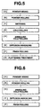
FIG.5 is a flow diagram illustrating the other
modified processes of the production method shown in FIG.1;
FIG.6 is a flow diagram illustrating the other
modified processes of the production method shown in FIG.2;
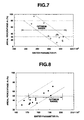
FIG.7 is a graph illustrating relationship between
sinter parameter P1 and areal percentage A1 of a part of
which Si content is 5.5 % or below in the sintered body;
and
FIG.8 is a graph illustrating relationship between
sinter parameter P2 and areal percentage A2 of a part of
which Si content is 6 % to 7 % in the sintered body.
DETAILED DESCRIPTION OF THE INVENTION
The silicon steel plate according to this invention is
coated with an insulating film on the surface of a sheet
metal obtained by powder-rolling metal powder containing
Si, or the surface of a sheet metal further subjected to
diffusion sintering after the powder rolling of the metal
powder.
In this case, magnetic steel powder, such as Fe-3wt%
Si, Fe-4.5wt% Si, Fe-6.5wt% Si, Fe-Si series alloying
composition and the like, may be used as the metal powder.
Also as the metal powder, pre-mixed powder obtained by
mixing powders in advance so as to accord with the chemical
compositions of the magnetic steel, pre-alloy powder
partially alloyed in advance and having the chemical
compositions of the magnetic steel and the like may be
used. It is possible to sufficiently utilize
characteristics of iron powder excellent in moldability by
using a powder mixture of the iron powder and Fe-Si alloy
powder containing Si of 8 to 65 wt%.
In the insulating film to be coated on the surface of
the sheet metal obtained by powder-rolling the
aforementioned metal powder (steel, iron and/or alloy
powders), inorganic matter is used, such as slurry-like
material containing MgO, SiO2, Al2O3, ZrO2, SnO2, TiO2, CrO3,
B2O3, Mg2SiO4 or the like, phosphoric acid and phosphates,
chromic acid and chromates, boracic acid and borates or so.
Organic matter is also used, such as acrilic resins,
alkyd resins, phenol resins, epoxy resins, melamine resins,
silicone resins, amino resins, styrene resins, ethylene
resins, polyvinyl chloride resins, polyvinyle acetate
resins, isocyanate resins, polyester, polyamido,
polystyrene, polypropylene, polycarbonate, polyurethane, or
so.
Furthermore, a mixture of the inorganic and organic
matter or two-layer structure composed of the inorganic and
organic matter may be also used.
Although roughness is formed on the surface of the
sheet metal owing to use of the metal powder, a pitch of
the roughness may be controlled by selecting particle size
of the metal powder.
Further, the depth of the roughness may be controlled
by selecting the reduction ratio at the time of powder
rolling or selecting the sintering temperature at the time
of diffusion sintering (diffusion annealing) of the sheet
metal.
Furthermore, the sheet metal obtained through the
powder rolling may be subjected to cold rolling, warm
rolling at a temperature lower than recrystallization
temperature, or hot rolling after the sintering, and the
depth of the roughness caused on the surface of the sheet
metal owing to use of the metal powder may be controlled by
selecting the reduction ratio at the time of the rolling.
In the silicon steel plate according to this
invention, the insulating film is formed on the surface of
the sheet metal after forming by the powder rolling, after
subjecting the sheet metal to the diffusion sintering or
after further subjecting the sintered sheet metal to
rolling such as the cold rolling. The insulating film can
be formed in a single layer or double layers by selecting
among the aforementioned various substances.
In this manner, the insulating film is not limited
only in the single layer and it is possible to form, for
example, Mg-Si complex oxide, such as forsterite (Mg2SiO4)
on the powder-rolled Fe-3% Si magnetic steel sheet as a
lower layer, and further form Cr-oxide and epoxy resin on
the phorstelite layer as an upper layer.
There are various methods for forming the insulating
film on the powder-rolled sheet metal, and the forming
method of the insulating film is not limited in the
specific method in this invention. For example, a brushing
method, a spraying method, a dipping method and the like
are available.
The thickness of the insulating film is suitable to be
0.5 to 5 µm or so, and the applicating amount of the
insulating film is suitable to be 0.5 to 3.0 g/m2
or so, however it is disirable to select the thickness and
the applicating amount in accordance with the coating
method, the type of the film, the number of the coating
layer and so on.
In the silicon steel plate provided with the
insulating film and obtained in this manner, the roughness
is formed on the surface of the powder-rolled sheet metal,
powder-rolled and sintered sheet metal or further cold-rolled
sheet metal because the metal powder is used,
accordingly the adhesion of the insulating film on the
surface of the silicon steel plate (sheet metal) becomes
excellent remarkably.
Further in such the powder-rolled silicon steel plate,
the insulating property becomes satisfactory by forming the
insulating film, the slidability after annealing and the
punching quality are also improved. The corrosion
resistance, oil resistance, solvent resistance, rusting
resistance and so are further improved, and the
magnetostriction is reduced by the tension caused by the
insulating film.
In a case where the magnetic steel powder of Fe-6.5wt%
Si steel is used as the metal powder, it is not necessary
to cope with the magnetostriction by cancelling the tension
with the insulating film since the magnetostriction of the
magnetic steel containing Si of 6.5 wt% is zero, so that
the high-tension film becomes unnecessary to be formed.
Furthermore, there is the roughness caused by the
metal powder on the surface of the powder-rolled or further
sintered sheet metal as mentioned above, therefore even
when gas is generated by vaporization of the organic
substances composing the insulating film at the time of
welding, the gas escapes through the roughness parts on the
surface of the sheet metal (lower face of the insulating
film), so that defects such as blistering, peeling or so
are never caused and the weldability is improved very
remarkably. Consequently, the space factor becomes higher
at the time of pile up the electric steel plates.
In the silicon steel plate according to another
embodiment of this invention, which is made from the metal
powder through powder rolling and diffusion annealing, and
of which roughness caused by the metal powder in the
surface thereof is controlled through cold rolling and so,
roops of magnetic flux is formed between pitches of the
roughness parts caused by the metal powder as the material,
so that magnetic domain is fractionated sufficiently and
suitably, the eddy-current loss becomes lower and the
silicon steel plate improved in the alternative magnetic
properties is provided.
As chemical compositions of the silicon steel plate,
the Si content is preferable to be 5 to 12 wt%. Namely, in
the case where the Si content of the silicon steel is less
than 5 wt%, the steel is possible to be produced through
the conventional rolling process using the ordinary ingot
steel and there is not so many merits obtained by
introducing the powder rolling process for the production
of the steel, so that it is not desirable to apply the
powder rolling in the production of the steel containing Si
less than 5 wt%. Meanwhile, the Si content in the steel is
not desirable to exceed 12 wt% because electric resistance
of the steel becomes lower in addition of decrease of the
suturated magnetism and the high-frequency property is
remarkably degraded.
As the metal powder used in the powder rolling, powder
of Fe-5 to 12 wt% Si alloy may be use, besides mixed powder
may be also used, which is a mixture of iron powder
excellent in the moldability and Fe-Si alloy powder
containing Si of 8 to 65 wt% and mixed in a ratio so as to
obtain the powder-rolled silicon steel plate with Si
content of 5 to 12 wt% after the diffusion annealing.
Such the iron powder with the desirable Si content and
the high-silicon steel powder are manufactured by the
reduction method, the pulverization method, the water
atomizing method, the mist atomizing method or the like,
and used after adjusting the particular size appropriately.
The pre-mixed powder obtained by mixing in advance, the pre-alloy
powder alloyed in advance or the like may be used,
and it is suitable to use the fine and irregular shaped
metal powder with particle size of under 100 mesh.
The iron powder and the high-silicon steel powder are
subjected to the powder rolling and further subjected to
the diffusion annealing in a non-oxidative atmosphere,
thereby obtaining annealed plate (solid) from the high-silicon
steel powder.
It is desirable to carry out the diffusion annealing
at a temperature of 1150 °C or above.
After the diffusion annealing, the roughness formed on
the surface of the powder-rolled and annealed sheet metal
during the sintering process of the metal powder by
subjecting to cold rolling, thereby controlling the
fractionation of magnet domain.
In this case, the pitch of the roughness on the
surface may be controlled by regulating the particle size
of the metal powder.
The depth of the roughness on the surface of the sheet
metal also may be controlled by regulating annealing
temperature at the time of the diffusion annealing.
Similarly, the depth of the roughness can be
controlled by regulation of reduction ratio at the time of
the cold rolling.
The rolling has also the advantage in that it is
possible to improve the space factor of the silicon steel
plates piled up so as to be used for the iron core or so as
compared with the case in which the rolling is not
performed.
In the method for producing the silicon steel plate
according to the other embodiment of this invention,
although the powder rolling of the metal powder, the
diffusion annealing of the powder-rolled sheet metal, the
rolling and so are carried out, the method may be divided
into a basic form and a simplified form.
The basic method for producing the silicon steel plate
according to this invention comprises, as shown in FIG.1,
the processes of [A] powder mixing process, [B] powder
rolling process, [C] sintering process, [D] cold rolling
process, [E] diffusion annealing process and [F] finish
rolling process.
Furthermore, the simplified method for producing the
silicon steel plate according to this invention comprises,
as shown in FIG.2, the processes of [A] powder mixing
process, [B] powder rolling process, [E'] diffusion
annealing process and [F] finish rolling process.
Various modification and variation can be applied to
the respective cases of the aforementioned basic and
simplified forms of the production method of the silicon
steel plate.
As the first example, the following process [G] may be
performed successively after the finish rolling process
[F];
The flow diagram in the case of adding the flattening
treatment process [G] to the basic method shown in FIG.1 is
shown in FIG.3, and the flow diagram in the case of adding
the flattening treatment process [G] to the simplified
method shown in FIG.2 is shown in FIG.4.
As another example of the modification, any one of the
following processes [H] and [I] may be carried out at least
one time in advance of the diffusion annealing process [E]
or [E'], especially in a case where the thin plate is
intended to be obtained with high dimensional accuracy;
The flow diagram of the modified method in which cold-rolling
and annealing [H] is executed in addition to the
basic method shown in FIG.1 and the aforementioned
flattening treatment process [G] is shown in FIG.5.
As the variation of the simplified method shown in
FIG.2, it is recommended to execute the following process
[H] once in advance of the diffusion annealing process
[E'];
The flow diagram of the modified method in which
annealing and cold rolling [H] is performed in addition to
the simplified method shown in FIG.2 is shown in FIG.6.
As iron powder used for powder material, it is
suitable to use the so-called reduced iron powder and
atomized iron powder. The iron powder manufactured from
iron carbonyl compounds is not suitable because it has
excessively fine grain size and nearly spherical shape, and
poor in the moldability in addition to its high price. As
Fe-Si alloy powder, it is suitable to use powder
manufactured by spraying water against the molten alloy. As
to the particle size of these iron and Fe-Si alloy powders,
it is suitable to use the powder comprising fine and
irregular shaped particles possible to pass 100 mesh or so.
Two kinds of material powders to be mixed are desirable in
the average and distribution of the particle size. If they
are different remarkably from each other, there is the
possibility that the two kinds of powders separates from
each other during the handling of the mixed powder.
The diffusion annealing of the powder-rolled metal is
carried out in the non-oxidative atmosphere, such as an
atmosphere of argon, nitrogen, hydrogen or so, or in
vacuum.
The aforementioned respective processes in the basic
production method have the following significance as
explained below.
That is, in the powder mixing process, low moldability
of the Fe-Si alloy powder with high Si content is improved
by mixing the iron powder excellent in the moldability so a
to carry out the powder rolling under the high moldability
in the whole body of the mixture.
The sintering of the sheet metal formed by the powder
rolling enables the product to be obtained as a result of
the succeeding cold rolling to exhibits strength at the
same time of maintaining the workability as the mixture.
The cold rolling is carried out in order to realize desired
thickness and increase the bulk density of the sintered
body by smashing holes in the sintered body and giving
internal strain energy, whereby it is possible to mitigate
the condition in the diffusion annealing of the next
process. In this time, "cold rolling" means the rolling in
the temperature range at which recrystallization is never
caused.
The cold-rolled sheet having an increased density in
this manner is uniformed in the composition and promoted to
be compacted by the diffusion annealing, thereby exhibiting
intended magnetic properties. The obtained sheet metal is
rolled into the predetermined thickness by the finish
rolling.
The skin pass rolling for finish has merits of not
only improvement of accuracy in the thickness of the
silicon steel plate to be obtained, but also improvement of
flexibility of the product. The improvement of the
flexibility is an unexpected profit, the advancement of the
workability improves the punching quality and enables to
manufacture the product with complicated or minute shape.
The simplified method is a production method for
proceeding microstructual uniformization of the alloying
compositions by diffusion, revelation of strength of the
sheet metal material and improvement of the magnetic
properties at the same time according to the diffusion
annealing by heating at a large sinter parameter than that
of the sintering process.
The all cases of the aforementioned production
methods, concrete conditions in the respective processes
should be selected so as to conform to the aforementioned
intention. Although Si content of the Fe-Si alloy powder to
be mixed with the iron powder can be selected from the wide
range of 8 to 65 wt%, excessive or too little content of Si
is not suitable. For example, alloy powder containing Si of
less than 8 % is not suitable for manufacturing 6.5 % Si
steel, especially in a case of manufacturing thin plate of
the steel because the oxygen content which is harmful to
the magnetic properties is apt to become higher and the
amount of iron powder required for adjusting the
compositions of the steel is decreased extremely, thereby
degrading the moldability of the powder mixture.
Contrarily, alloy powder containing too much Si is also not
suitable since the blending ratio of the Fe-Si alloy powder
against the iron powder becomes lower and it is difficult
to obtain uniformity of the powder mixture.
This invention has a meaning in producing the silicon
steel plate containing high Si content, that is Si content
higher than 5 % which is difficult to realize through the
conventional technique, and Fe-Si alloy is required to
contain Si more than certain limitation value, however too
much content of Si is also disadvantageous in consideration
of the present situation that the upper limit of Si to be
contained Fe-Si alloy steel as the magnetic materials is 11
to 12 % in practical application. Concerning the blending
ratio of the iron powder and the Fe-Si alloy powder,
unbalanced combination such as the ratio 95:5 or above by
weight is not desirable from a view point of ensuring the
uniformity of the mixture, and it is preferable to select
the ratio 90:10 and further preferable to select the ratio
close to the ratio 50:50.
In order to the above conditions, Fe-Si alloy powder
of which Si content is more than 10 % and does not exceed
30 % so remarkably can be used easily in general. There is
a eutectic point (Fe3Si, melting point : 1200 °C) at a point
of 18 % Si in the Fe-Si alloy series, accordingly, it is
advisable to use powder of the above-mentioned eutectic
alloy.
As to the combination of the two kinds of powders,
various cases of the combination are selectable between the
following examples on two extremes:
From view points of economical efficiency and
moldability of the powder mixture, the former is rather
advantageous. Especially in a case of obtaining the thin
plate, it is recommended to use the iron powder in the
large quantity in order to ensure the moldability. It is
facilitated to realize the uniform alloying compositions by
using the powder mixture of which deviation of the
microscopic compositions is smaller, that is the later
combination of the powders. In addition to the above, it is
necessary to regard the value of Si content of the silicon
steel plate to be manufactured as important, and the
concrete combination of the chemical compositions should be
decided by considering these various factors synthetically.
The sintering process is a process for the purpose of
obtaining sintered body of which holes is easy to be
smashed in the succeeding cold rolling process without
promoting diffusion so much. The sintering does not proceed
in the practical speed at a temperature lower than 950 °C of
the lower limit of the sintering temperature range, and the
upper limit of 1400 °C is set because the alloy powder is
molten at a temperature higher than 1400 °C.
This sintering process should be executed under
conditions that areal percentage of the part of which Si
content is 5.5 % or below is in a range of 30 to 80 % in
order to ensure the workability at the proceeding process
as mentioned above. "The part of which Si content is 5.5 %
or below" is, of course, a part holding the workability,
therefore if the sintering is advanced until the areal
percentage of this part becomes lower than 30 %, the
workability is remarkably degraded in the successive
process. The other side, in the sintering such that
undiffused part remains as much as above 80 %, the sintered
body is insufficient in the strength and the rolling work
becomes difficult in itself. It is possible to measure the
Si content by EPMA (Electron Probe Micro-Analyzer) as well
known by the person having ordinary skill in the art.
In this stage, on the way to sintering, a large number
of the holes exist in the sheet metal, so that the
diffusion rate is high and sinter parameter P
1 is expressed
as following equation;
P1 = T × (20 + log10t)
wherein
It has been found that relationship between the sinter
parameter P1 and the areal percentage of Si-diffusion can
be rearranged in comparatively good order as shown in
FIG.7.
In FIG.7, value of the sinter parameter P1 for setting
the areal percentage A1 of "the part of which Si content is
5.5 % or below" in the aforementioned optimum range of 30
to 80 % is in a range of (230∼310) × 102, and sintering
conditions corresponding to such the sinter parameter value
are 950 °C × 30 min and 1350 °C × 10 min, respectively.
Therefore, it is possible to select the actual operating
condition as combination of the temperature and time within
the aforementioned range. Especially desirable value of
sinter parameter P1 is within a range of (270∼280) × 102
approximately as is apparent from FIG.7.
As against the aforementioned sintering, the diffusion
annealing is a process for contriving to uniformize the
compositions by diffusion of Si and directing the increase
of the density, therefore it is necessary to heat at a high
temperature of 1150 °C or more. Although the diffusion
proceeds in some degree even in a temperature lower than
above, it is not possible to expect the increase of the
density and the magnetic properties of the steel plate
product is not improved, the effect on the improvement of
the magnetic properties becomes higher according as the
heating temperature is raised, but is saturated in the
region of 1350 °C. The alloy is molten at a temperature
higher than 1400 °C. The diffusion annealing can be
performed either in the batch furnace or the continuous
furnace, however it is necessary to apply the anti-seizure
agents such as almina for fear that seizure may be caused
in the works overlapping one another in a case of using the
batch furnace.
This diffusion annealing process should be executed
under conditions that a part of which Si content is 6 to 7
% amount to 50 % or more in areal percentage, particular
grains are not coarsened excessively and workability can be
ensured in the following process. Sinter parameter P
2 in
the diffusion annealing stage is expressed as following
equation;
P2 = T × (10 + log10t)
wherein
It has been found that relationship between the sinter
parameter P2 and the areal percentage of Si-diffusion can
be rearranged as shown in FIG.8.
In the FIG.8, value of the sinter parameter P2 for
setting the areal percentage A2 of "the part of which Si
content is 6 to 7 %" in the optimum range of 50 % or more
is in a range of (170∼200) × 102, and sintering conditions
corresponding to such the parameter value are 1200 °C × 30
min (or 1150 °C × 60 min) and 1350 °C × 120 min,
respectively. Accordingly, the actual operating condition
may be selected from the combination of the temperature and
time within the aforementioned range. Desirable value of
sinter parameter P2 is especially in a range of (180∼200) ×
102 approximately as is apparent from FIG.8.
The annealing process is an operation for facilitating
the following cold rolling by relieving the strain caused
by rolling, and it is not possible to improve the strength
of the product in this process. The relieving of work-strain
does not proceed at a temperature lower than 600 °C,
however even if the annealing temperature is raised at
950 °C or above, further improvement of the workability can
not be expected any longer and the energy is merely
dissipated wastefully.
According to the above-mentioned method, it is
possible to obtain the silicon steel plate of which Si
content is 5 to 12 wt%, thickness is 0.05 to 0.50 mm
(practical thickness is in a range of 0.10 to 0.35 mm),
chemical compositions are uniform and workability is
excellent, and the product according to this production
method is also included in the scope of this invention.
EXAMPLE 1
Next, the invention will be explained in detail on
basis of following examples, needless to say, this
invention is not limited only in these examples.
The silicon steel plates were made by using two kinds
of metal powder as raw materials, and the two kinds of
powder mixtures of Fe-3.5wt% Si powder and Fe-6.5wt% Si
powder were prepared.
First of all, the metal powder was charged into the
hopper from the upper part, and powder-rolled sheet metal
was formed by subjecting the metal powder supplied
successively from the bottom part of the hopper to the
powder rolling, and then the powder-rolled sheet metal was
subjected to primary sintering at a temperature of 700 °C,
subsequently subjected to secondary sintering at a
temperature of 1300 °C. Consequently, four kinds of powder-rolled
sheet metal having thickness of 0.1 mm and
respective surface roughness as shown in Table 1 were
obtained by further performing cold rolling, warm rolling
and hot rolling in combination.
| Sheet metal No. | Chemical composition | Surface roughness Ra (µm) | Production method | Remarks |
| 1 | Fe-3.5wt% Si | 0.31 | Powder rolling + Sintering | Inventive Example |
| 2 | Fe-3.5wt% Si | 0.63 |
| 3 | Fe-6.5wt% Si | 0.30 |
| 4 | Fe-6.5wt% Si | 0.61 |
| 5 | Fe-3.5wt% Si | 0.29 | Melting + rolling (Ingot steel) | Comparative Example |
| 6 | Fe-6.5wt% Si | 0.32 | Rolling + CVD |
Next, two kinds of insulating films shown in Table 2
were applied on the respective sheet metal shown in Table 1
through the roll coating method and put together by baking
under conditions shown in Table 2 after drying.
In this time, two kinds of sheet metal manufactured by
melting method (ingot steel) and rolled into 0.1 mm
thickness and having Si content of 3.5 wt% and 6.5 wt% were
also used as comparative examples.
| Insulating film No. | Ingredients | Amount of application (g/m2) | Baking temperature (°C) |
| 1 | Chromic acid | 45wt% | 2 | 450 |
| Boric acid | 10wt% |
| Magnesium oxide | 15wt% |
| Ethylen glycol | 10wt% |
| Epoxy resin | 20wt% |
| 2 | Silicone resin | 2 | 300 |
Evaluation of various characteristic were carried out
with respect to the silicon steel plates coated with
insulating films according to the above-mentioned process,
and the results are shown in Table 3. The respective
characteristic of the silicon steel plates shown in Table 3
were evaluated in accordance with the following procedure.
(1) Surface insulation resistance
The surface insulation resistance was measured
according to the method specified in JIS C 2550 (1986)
"Methods of Test for Electrical Steel Sheets"
(2) Adhesion
The adhesion was indicated with the minimum diameter
of bent portion at the time when the outer insulating film
does not separate from the steel plate by peeling test
using the adhesive tape even by bending the silicon steel
plate with the insulating film at an angle of 180°.
(3) Corrosion resistance
The corrosion resistance was evaluated with percentage
of rusting area after leaving the silicon steel plate with
the insulating film in an atmosphere of 40 °C - 80 °C RHD for
100 hrs.
(4) Punching quality
The punching quality was indicated with the number of
punchings at the time when the height of burr comes up to
50 µm at clearance of 5 % using the steel die of SKD-1
(alloy tool steel containing Cr). The test was discontinued
at 2 million times which are the practical life time.
As is obvious from Table 3, it was confirmed that the
silicon steel plate excellent in the insulation property,
corrosion resistance, adhesion, punching quality and having
high space factor can be obtained according to this
invention.
EXAMPLE 2
The high-silicon steel having chemical compositions
shown in Table 4 were molten, and then the high-silicon
steel powder having particle size distribution as shown in
Table 5 were obtained by water aotmizing method.
| C | Si | Mn | P | S | Soℓ.Aℓ | N | Fe |
| 0.008 | 11.76 | 0.08 | 0.020 | 0.025 | 0.025 | 0.009 | Baℓ . |
| -350 | +350/-200 | +200/-150 | +150/-100 | +100/-50 |
| 51.7 | 37.0 | 11.2 | 0.1 | 0 |
Next, a powder preparation with composition of Fe-6.5wt%
Si was obtained by mixing the above-mentioned high-silicon
steel powder and iron powder, and the powder
preparation was powder-rolled into sheet metal of 0.11 mm
in thickness, successively the powder-rolled sheet metal
was subjected to diffusion annealing at at temperature of
1300 °C as shown in Table 6.
Subsequently, the diffusion-annealed (sintered) sheet
plate was subjected to cold rolling with respective
reduction ratio shown in Table 6, and three kinds of high-silicon
steel plates with a thickness of 0.10 mm were
obtained by further subjecting to tension annealing. The
results of measuring the pitch of the roughness caused by
using the metal powder and core loss are also shown in
Table 6.
| No. | Diffusion annealing temperature (°C) | Cold rolling reduction ratio (%) | Pitch of roughness (mm) | Depth of roughness (mm) |
| Inventive example | 9 | 1300 | 3 | X = 0.04 | X = 0.030 |
| 10 | 1300 | 5 | X = 0.07 | X = 0.023 |
| 11 | 1300 | 8 | X = 0.11 | X = 0.012 |
Results shown in Table 7 were obtained by measuring
core loss of the respective silicon steel plates after
subjecting the above-mentioned steel plates to annealing at
950 °C for 1 hour.
| No. | Core loss (Bm = 1000) |
| | 1KHz | 3 KHz | 5 KHz | 10 KHz |
| Inventive example | 9 | 32.3 | 122.6 | 238.5 | 635.6 |
| 10 | 30.1 | 112.8 | 217.4 | 552.2 |
| 11 | 19.4 | 89.4 | 183.7 | 531.7 |
As shown in Table 7, it was confirmed that it is
possible to obtain the high-silicon steel plate low in core
loss and having improved alternative magnetic property
according to this invention.
EXAMPLE 3
As raw material powders, iron powder and Fe-18% Si
alloy powder were manufactured by water atomizing method,
and powders passed through a 100 mesh seive were collected.
The respective powders were confirmed that average particle
size was 40 µm, approximately. These powders were mixed in
the ratio 60:34 by the tumbler so that Si content in the
mixture may be 6.5 wt%. Nine kinds of silicon steel plates
were manufactured by treating the powder mixture in the
following various processes.
In the powder rolling, the horizontal rolling mill
provided with two rolls of 200 mm diameter and 240 mm in
length was used, the powder mixture was supplied to the
rolling mill through the vibrator plate and the powder
rolling was performed at constant pressure of 70 ton in
kiss roll method. In the respective processes, the
diffusion annealing is executed by using the batch furnace
or the continuous furnace, and the tension annealing was
carried out in the condition of 750 °C × 2 min and the
tension of 3 kg/mm2 except for special mention of the
condition. The finish rolling (skin pass rolling) was
carried out in the reduction ratio of 0.5 to 5 %.
Comparative example No.5 (prior art)
Powder mixing ― Powder rolling (thickness : 0.10 mm)
― Sintering (batch furnace, 1250 °C × 1 hour, thickness of
endproduct : 0.10 mm)
Inventive example No.12 (FIG.1)
[A] Powder mixing ― [B] Powder rolling (thickness :
0.11 mm) ― [C] Sintering (batch furnace, 1050 °C × 1 hour)
― [D] Cold rolling (thickness : 0.105 mm) ― [E] Diffusion
annealing (batch furnace, 1200 °C × 1 hour) ― [F] Finish
rolling (thickness of endproduct : 0.10 mm)
Inventive example No.13 (No.12 + [H])
[A] Powder mixing ― [B] Powder rolling (thickness :
0.12 mm) ― [C] Sintering (batch furnace, 1050 °C × 1 hour)
― [D] Cold rolling (thickness : 0.11 mm) ― [H] Annealing
(850 °C × 1 hour) ― Cold rolling (thickness : 0.105 mm) ―
[E] Diffusion annealing (batch furnace, 1200 °C × 1 hour) ―
[F] Finish rolling (thickness of endproduct : 0.10 mm)
Inventive example No.14 (No.13 + [G], FIG.5)
[A] Powder mixing ― [B] Powder rolling (thickness :
0.12 mm) ― [C] Sintering (1050 °C × 1 hour) ― [H] Cold
rolling (thickness : 0.11 mm) ― Annealing (850 °C × 1
hour) ― Cold rolling (thickness : 0.105 mm) ― [E]
Diffusion annealing (batch furnace, 1200 °C × 1 hour) ―
[F] Finish rolling (thickness of endproduct : 0.10 mm) ―
[G] Flattening treatment
Inventive example No.15 (FIG.3)
[A] Powder mixing ― [B] Powder rolling (thickness :
0.11 mm) ― [C] Sintering (continuous furnace, 1050 °C × 6
min) ― [D] Cold rolling (thickness : 0.105 mm) ― [E]
Diffusion annealing (continuous furnace, 1285 °C × 8 min) ―
[F] Finish rolling (thickness of endproduct : 0.10 mm) ―
[G] Flattening treatment
Inventive example No.16 (FIG.2)
[A] Powder mixing ― [B] Powder rolling (thickness :
0.105 mm) ― [E'] Diffusion annealing (batch furnace, 1200 °C
× 1 hour) ― [F] Finish rolling (thickness of endproduct :
0.10 mm)
Inventive example No.17
[A] Powder mixing ― [B] Powder rolling (thickness :
0.120 mm) ― [H] Annealing (850 °C × 0.5 hours) ― Cold
rolling (thickness : 0.110 mm) ― [C] Sintering (batch
furnace, 1200 °C × 1 hour in vacuum) ― Cold rolling
(thickness : 0.105 mm) ― [E'] Diffusion annealing (batch
furnace, 1200 °C × 1 hour) ― [F] Finish rolling (thickness
of endproduct : 0.10 mm)
Inventive example No.18 (FIG.4)
[A] Powder mixing ― [B] Powder rolling (thickness :
0.105 mm) ― [E'] Diffusion annealing (continuous furnace,
1285 °C × 8 min) ― [F] Finish rolling (thickness of
endproduct : 0.10 mm) ― [G] Flattening treatment
Inventive example No.19 (FIG.6)
[A] Powder mixing ― [B] Powder rolling (thickness :
0.105 mm) ― [E'] Diffusion annealing (continuous furnace,
1325 °C × 2 min) ― [F] Finish rolling (thickness of
endproduct : 0.10 mm) ― [G] Flattening treatment
Inventive example No.20
[A] Powder mixing ― [B] Powder rolling (thickness :
0.11 mm) ― [C] Sintering (continuous furnace, 1050 °C × 6
min) ― [D] Cold rolling (thickness : 0.105 mm) ― [E]
Diffusion annealing (continuous furnace, 1285 °C × 8 min) ―
[F] Finish rolling (thickness of endproduct : 0.10 mm) ―
[J] Magnetic annealing (batch furnace, 900 °C × 2 hours in
vacuum) ― [G] Flattening treatment
The density was measured as to the obtained silicon
steel plates of comparative example No.5, inventive example
Nos.12, 13, 14, 16 and 17, and the specific resistance was
further measured as to the steel plates of comparative
example No.5 and inventive example No.12. These results are
shown together in Table 7.
| No. | Density ρ (g/cm3) | Specific resistance (µΩcm) |
| Comparative example | 5 | 7.32 | 80 |
| Inventive example | 12 | 7.31 | 80 |
| 13 | 7.38 | - |
| 14 | 7.42 | - |
| 16 | 7.36 | - |
| 17 | 7.33 | - |
The value of the direct current magnetic properties
are shown in Table 8.
| No. | | B1 | B2 | B10 | B25 | Hc(Oe) |
| Comparative example | 5 | 8200 | 9350 | 11800 | 12700 | 0.32 |
| Inventive example | 12 | 9800 | 10900 | 11200 | 12800 | 0.25 |
| 13 | 8750 | 9780 | 11850 | 13010 | 0.28 |
| 14 | 8860 | 9640 | 11800 | 12930 | 0.27 |
| 15 | 8750 | 9580 | 11700 | 12900 | 0.38 |
| 16 | 8700 | 9480 | 11500 | 12700 | 0.46 |
| 17 | 8100 | 9250 | 11700 | 12800 | 0.30 |
| 18 | 8710 | 9500 | 11600 | 12600 | 0.52 |
| 19 | 8680 | 9480 | 11300 | 12600 | 0.40 |
| 20 | 9630 | 10540 | 11800 | 12900 | 0.34 |
The alternative magnetic properties are shown in Table
9.
| No. | | W10/50 | W10/100 | W10/400 | W10/1K | W10/2K | W10/5K | W10/10K |
| Comparative example | 5 | 0.81 | 1.86 | 8.52 | 33.8 | 70.3 | 261.1 | 714.3 |
| Inventive example | 12 | 0.74 | 1.84 | 8.00 | 31.6 | 68.6 | 253.6 | 710.2 |
| 13 | 0.85 | 1.95 | 9.10 | 35.5 | 73.5 | 280.5 | 784.4 |
| 14 | 0.82 | 1.91 | 8.86 | 34.7 | 71.9 | 277.9 | 778.8 |
| 15 | 0.80 | 1.90 | 9.00 | 36.0 | 77.8 | 288.4 | 804.2 |
| 16 | 0.88 | 2.13 | 10.04 | 51.1 | 92.3 | 341.9 | 981.7 |
| 17 | 0.78 | 1.88 | 6.81 | 34.2 | 70.8 | 274.9 | 771.6 |
| 18 | 0.90 | 2.15 | 10.50 | 52.3 | 96.6 | 364.6 | 1005.9 |
| 19 | 0.85 | 2.00 | 9.80 | 49.5 | 87.3 | 320.9 | 960.6 |
| 20 | 0.72 | 1.70 | 8.10 | 32.0 | 70.0 | 288.0 | 804.0 |
| Bm = 10 KG (unit : w/kg) |
Effect of the flattening treatment was confirmed by
comparing flatness of the sample plates cut out from the
steel plates of inventive example No. 13 and 14, namely the
flatness was compared by measuring the maximum height at
the time of placing the sample plates of 85 mm in width and
1 m in length on the horizontal level block. The results
are shown in Table 10.
| No. | Flatness (µm/m) |
| Inventive example | 13 | 836 |
| 14 | 235 |
Furthermore, the flatness to be obtained by the
tension annealing was compared in the various conditions as
to the steel plate of inventive example No.15, and the
results are shown in Table 11.
| No. | Tension annealing condition | Flatness (µm/m) |
| | Temperature (°C) | Tension (kgf/mm2) |
| Inventive example No.15 | Not executed | - | 1040 |
| 600 | 4 | 965 |
| 700 | 2 | 784 |
| 700 | 3 | 669 |
| 700 | 4 | 230 |
| 750 | 2 | 320 |
| 750 | 3 | 168 |
| 800 | 3 | 246 |
| 1000 | 2 | Fractured |
The advantage produced by the skin pass rolling in the
finish rolling process [G], that is the improvement of the
flexibility is apparent from the following results (shown
in Table 12) of the transverse test executed as to the
steel plate of inventive example No.12.
| No. | Transverse rupture strength (MPa) | Deflection (mm) |
| Inventive example No. | After diffusion annealing | 998 | 0.80 |
| After skin pass rolling | 1986 | 1.98 |
| Test piece : 3×5×40 mm, Gauge length : 25 mm |
According to this invention, it is possible to make up
for weakness of low workability in the Fe-Si alloy by the
excellent workability of the iron powder, and possible to
easily manufacture the high-silicon steel plate containing
Si of 5 to 12 wt% which has been difficult to be
manufactured conventionally. The thickness of the silicon
steel plate can be accurately controlled by subjecting to
the skin pass rolling in the finish rolling process. The
skin pass rolling improves flexibility and workability of
the silicon steel and facilitates the punching of the steel
plate, and it is favourable to manufacture the iron core of
the transformer as main usage of the silicon steel plate.
FUrthermore, it is confirmed that the silicon steel plate
subjected to the tension annealing exhibits the high
flatness.