EP1052028A1 - Resonance device, such as beater or force generator - Google Patents
Resonance device, such as beater or force generator Download PDFInfo
- Publication number
- EP1052028A1 EP1052028A1 EP00400995A EP00400995A EP1052028A1 EP 1052028 A1 EP1052028 A1 EP 1052028A1 EP 00400995 A EP00400995 A EP 00400995A EP 00400995 A EP00400995 A EP 00400995A EP 1052028 A1 EP1052028 A1 EP 1052028A1
- Authority
- EP
- European Patent Office
- Prior art keywords
- mass
- main
- generator according
- coupled
- generator
- Prior art date
- Legal status (The legal status is an assumption and is not a legal conclusion. Google has not performed a legal analysis and makes no representation as to the accuracy of the status listed.)
- Granted
Links
Images

Classifications
-
- B—PERFORMING OPERATIONS; TRANSPORTING
- B06—GENERATING OR TRANSMITTING MECHANICAL VIBRATIONS IN GENERAL
- B06B—METHODS OR APPARATUS FOR GENERATING OR TRANSMITTING MECHANICAL VIBRATIONS OF INFRASONIC, SONIC, OR ULTRASONIC FREQUENCY, e.g. FOR PERFORMING MECHANICAL WORK IN GENERAL
- B06B1/00—Methods or apparatus for generating mechanical vibrations of infrasonic, sonic, or ultrasonic frequency
- B06B1/10—Methods or apparatus for generating mechanical vibrations of infrasonic, sonic, or ultrasonic frequency making use of mechanical energy
- B06B1/12—Methods or apparatus for generating mechanical vibrations of infrasonic, sonic, or ultrasonic frequency making use of mechanical energy operating with systems involving reciprocating masses
- B06B1/14—Methods or apparatus for generating mechanical vibrations of infrasonic, sonic, or ultrasonic frequency making use of mechanical energy operating with systems involving reciprocating masses the masses being elastically coupled
-
- E—FIXED CONSTRUCTIONS
- E02—HYDRAULIC ENGINEERING; FOUNDATIONS; SOIL SHIFTING
- E02D—FOUNDATIONS; EXCAVATIONS; EMBANKMENTS; UNDERGROUND OR UNDERWATER STRUCTURES
- E02D3/00—Improving or preserving soil or rock, e.g. preserving permafrost soil
- E02D3/02—Improving by compacting
- E02D3/046—Improving by compacting by tamping or vibrating, e.g. with auxiliary watering of the soil
- E02D3/068—Vibrating apparatus operating with systems involving reciprocating masses
-
- F—MECHANICAL ENGINEERING; LIGHTING; HEATING; WEAPONS; BLASTING
- F16—ENGINEERING ELEMENTS AND UNITS; GENERAL MEASURES FOR PRODUCING AND MAINTAINING EFFECTIVE FUNCTIONING OF MACHINES OR INSTALLATIONS; THERMAL INSULATION IN GENERAL
- F16F—SPRINGS; SHOCK-ABSORBERS; MEANS FOR DAMPING VIBRATION
- F16F7/00—Vibration-dampers; Shock-absorbers
- F16F7/10—Vibration-dampers; Shock-absorbers using inertia effect
- F16F7/1005—Vibration-dampers; Shock-absorbers using inertia effect characterised by active control of the mass
- F16F7/1011—Vibration-dampers; Shock-absorbers using inertia effect characterised by active control of the mass by electromagnetic means
Definitions
- the subject of the present invention is a resonant device comprising a mass-spring system associating a main mass and a spring, usable as a passive or active drummer tuned to muffle a vibration, or again as a dynamic force generator to apply forces to a structure.
- the present invention aims to allow a frequency setting of the device.
- the invention relates to a passive resonant device or active with a mass-spring system composed of a main mass comprising at least one main mass element and at least one element of spring characterized in that it comprises at least one additional mass comprising at least one additional mass element and a coupling device capable of coupling the additional mass to the main mass and to decouple it, in order to modify the device tuning frequency.
- the device can be characterized in that it comprises at least one electromagnetic assembly comprising two complementary devices, the first has at least one electromagnetic part and the second of which has at least one electromagnet, one of the two complementary devices being coupled to the main mass, and the other complementary device being coupled to a mass additional, the two devices being arranged opposite one another, so such that, when one of the electromagnets is activated, two complementary devices are mechanically integral, so that the main mass and said mass additional are coupled.
- At least one electromagnetic part can be coupled by example elastically to the main earth, at least one electromagnet then being coupled to said additional mass.
- Said elastic coupling which is for example made with a flexible blade, can have a degree of elastic freedom in a direction substantially perpendicular to a main direction of the oscillations of the main mass, for example the direction of effort generation.
- the device can be characterized in that a first device complementary has two electromagnetic parts spaced from each other and integral with said flexible blade, and in that a second complementary device has two electromagnets arranged opposite the two parts electromagnetic.
- the two electromagnets can be integral with at least one connecting piece.
- At least one additional mass can be kept in position by an elastic device which has a degree of elastic freedom in one direction substantially parallel to a main direction of mass oscillations main, this elastic device having for example at least one elastic blade.
- the present invention allows good control of the amplitude of the oscillations, and / or allows the transmission of forces important.
- the invention provides a dynamic force generator comprising a main mass-spring system composed of a main mass comprising at least one main mass element of mass m2 and at least one spring element of stiffness K2, characterized in that it comprises an auxiliary mass-spring system which is coupled to the main mass-spring system and which is composed of an auxiliary mass of mass m3 and at least one auxiliary spring element of stiffness K3, l ' assembly having a first and a second resonant frequency, denoted respectively f 0 and f 2 , and an anti-resonant frequency f 1 , with f 0 ⁇ f 1 ⁇ f 2 .
- the generator can in particular operate at the frequency f 0 and / or at the frequency f 1 , for example using an excitation device to actuate the generator between the frequencies f 0 and f 2 and in particular at the frequency d 'anti-resonance f 1 .
- the generator can normally operate at any frequency. Its use is not limited to the frequencies f 0 , f 1 , f 2 , but, the characteristic of anti-resonance at frequency f 1 is therefore not exploited.
- the advantage of operating at the frequency f 1 is that it allows operation at reduced amplitude, which makes it practically impossible to saturate the actuator mechanically, while the we always benefit from mechanical amplification.
- the only limitation being the maximum current admissible by the generator, it is possible to generate significant forces which can be transmitted to a structure.
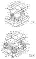
- the device shown in Figure 1 includes an element mass 1 of mass m3 which, in the case of an active mixer, includes a generator electrodynamics or variable reluctance.
- a plate 5 fixed to the element 1 carries to its ends two springs 3 which give the mass-spring system thus formed stiffness K3. These two springs 3 rest on cylindrical pads 31 carried by a plate 2 which is coupled to a structure whose vibrations are to be suppressed or to which we want to communicate vibrations.
- the plate 5 carries a plate 6 at ends of which are fixed the branches 81 of two springs 8 which have two opposite branches 81 and 83 separated by a slot 82 and connected together by the sectors 85.
- the element 1 has a plate 7 at the part bottom of which is mounted a plate 6 at the ends of which are fixed branches 91 of two springs 9 similar to springs 58 and which have two opposite branches 91 and 93 separated by a slot 92 and connected by sectors 95.
- the branches 83 and 93 of the springs 8 and 9 are integral with the uprights 84 perpendicular to the plane of the plate 2 and which are integral with the latter. Plates 6 being integral with the plate 5 and the plate 7, the springs 8 and 9 make it possible to center the 1-spring 3 mass assembly during its movements perpendicular to the plate 2.
- the uprights 84 can be used to dispose of the masses additional which can be coupled to main ground 1 or decoupled from this, in order to vary the dynamic mass of the drummer, and therefore to modify the resonance conditions.
- a module 10 of additional mass to add a mass m4 to the main mass m3 has two electromagnets 102 mounted at both ends of the link arm 110 and 111, notched at 112 in view of the passage of an upright 84.
- Springs 115 having arms 116 form a zigzag paths, which are separated by slots 117 extending from edges opposite 113 and 119. These springs 115 serve to suspend and guide the mass m4 which consists of the two electromagnets 102 and the connecting parts 110 and 111.
- Each spring 115 is mounted on two pairs of tie rods 101 and 103.
- the tie rods 101 are integral with a fixed plate 120 integral with its opening 125 the amount 84.
- the tie rods 103 mounted opposite the tie rods 101, are integral with the corresponding electromagnet 102.
- For each electromagnet there are two pairs upper and lower of tie rods 101, and two pairs, upper and lower of tie rods 103. This gives a degree of freedom parallel to the direction of displacement of the element 1, that is to say perpendicular to the plane of the plate 2.
- FIG. 5 shows the device 20 which makes it possible to couple the mass additional m4 (ref. 10) to main mass 3. It has two masses ferromagnetic 204 for example laminated mounted at the end of a blade flexion 201 fixed at its openings 202 on a lateral face of the plate 7. This bending blade has a high stiffness in the direction of movement of the mass 1 of the mixer, that is, of the vibration to be generated or to be attenuated, but a much lower stiffness in the plane perpendicular to said direction of movement.
- the ferromagnetic masses 204 are located opposite the electromagnets 102. In this way, the magnetic circuits of the electromagnets 102 close on the magnetic masses 204.
- the coupling is carried out as follows: the activation of the electromagnets 102 causes the application of masses 204 on the surface of the electromagnets 102, and therefore a mechanical coupling of the additional mass. Given that the plate 7 is integral in displacement with the main mass, the mass additional is also driven in a movement parallel to the axis of uprights 84, which is made possible by the suspension effect provided by the springs lamellar 115.
- Figures 2 to 5 allows for a variation of the mass of the mixer by coupling one or more additional masses specified values, which allows you to change the frequency of the mixer in order to process vibrations whose frequency can change.
- the four are simultaneously excited electromagnets to couple the two modules 10 of the main element 1.
- leaf springs 115 which are sufficiently stiff in the plane perpendicular to the direction of movement of the beater to avoid their movement in this plane and flexible enough in the direction of movement of the drummer to accompany him in his movements, the flexibility being fixed so as to achieve with the new mass and characteristics drummer's antecedents the new chord of it.
- the stiffness of these blades can be supplemented by those of springs acting in parallel with them to achieve the new chord, (which amounts, in a way, to connecting to the initial drummer a new beater placed in parallel).
- the device described allows generate significant dynamic forces at low frequency according to a setpoint supplied to an electronic unit.
- the effort is generated inertially, that is to say using the principle of action-reaction applying to a mass excited in effort.
- the mass is constituted by the mass of the generator body.
- the invention can be implemented using a generator variable reluctance incorporated into main mass 1 and its control via a digital computer whose algorithm linearizes it in a manner known per se force-displacement characteristic, both as a force and mass generator in a mass-spring system in order to introduce significant forces at low frequency in a structure.
- the mass m2 is made up of the mass mobile of an electromagnetic generator (with variable reluctance) or of a generator electrodynamics.
- the mass m2 and the elastic connection of rigidity K2 constitutes a oscillating mechanical system whose amplification can be exploited at resonance in the limit of admissible travel.
- This technique is commonly used with generators electrodynamics (coils plunging into a constant field).
- variable reluctance generators which provide significant efforts in a volume then reduced is hardly possible in low frequency, because their travel is limited by the need for air gaps weak to generate effort.
- the solution is obtained by exciting an oscillating system mass-spring at a frequency close to its natural frequency. We then benefit from amplification coefficient of such a system, without the need to generate an effort important initial.
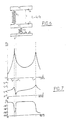
- the assembly diagram (see Figure 6) implements a generator having a mass m2 suspended with a stiffness K2, which excites the mass m3 of the auxiliary mass-spring system, having an auxiliary mass m3 and having a stiffness K3.
- the mass m2 consists of the main mass 1 which is coupled to a generator of which it constitutes the mobile mass.
- the stiffness K2 is defined by the springs 3.
- Z 2 / U [(m2 + m3) p 2 + K3)] / [m2.m3.p 4 + (K2.m2 + m2.K3 + K2.m3) p 2 + K2.K3]
- m2 - ⁇ f 1 1 ⁇ 2 ⁇ K 3 / ( m 2 + m 3)
- the device has two resonance frequencies f 0 and f 2 for which there is a large amplification of the force generated, and an anti-resonance frequency f1 corresponding to the proper mode of the masses m2 + m3 on the spring K3.
- this amplitude z 2 can become very large and lead to saturation, or even destruction of the actuator. On the other hand, we note that this amplitude becomes very low around the antiresonance f 1 . In the case of a variable reluctance generator, this amplitude z 2 is the variation of the air gap, which means that it is therefore possible to use a small air gap and consequently have a large generated force.
- the Ft / U ratio is always greater than 1, which that we still take advantage of mechanical amplification.
- the generator is preferably of the variable reluctance type with an auxiliary mobile mass of value m 2 , the main mass being adjusted to the value m3.
Landscapes
- Engineering & Computer Science (AREA)
- General Engineering & Computer Science (AREA)
- Structural Engineering (AREA)
- Mechanical Engineering (AREA)
- Life Sciences & Earth Sciences (AREA)
- Paleontology (AREA)
- Physics & Mathematics (AREA)
- Mining & Mineral Resources (AREA)
- Soil Sciences (AREA)
- Civil Engineering (AREA)
- Environmental & Geological Engineering (AREA)
- Agronomy & Crop Science (AREA)
- General Life Sciences & Earth Sciences (AREA)
- Electromagnetism (AREA)
- Apparatuses For Generation Of Mechanical Vibrations (AREA)
- Electrotherapy Devices (AREA)
- Compositions Of Oxide Ceramics (AREA)
- Inorganic Compounds Of Heavy Metals (AREA)
- Vibration Prevention Devices (AREA)
Abstract
Description
La présente invention a pour objet un dispositif résonant comprenant un système masse-ressort associant une masse principale et un ressort, utilisable comme batteur passif ou actif accordé de manière à étouffer une vibration, ou bien encore comme générateur d'efforts dynamiques pour appliquer des efforts à une structure.The subject of the present invention is a resonant device comprising a mass-spring system associating a main mass and a spring, usable as a passive or active drummer tuned to muffle a vibration, or again as a dynamic force generator to apply forces to a structure.
L'accord est obtenu en choisissant la masse et la raideur du ressort pour que par exemple la fréquence propre de l'ensemble masse-ressort soit égale à celle de la vibration à générer ou à étouffer.The agreement is obtained by choosing the mass and the stiffness of the spring so that for example the natural frequency of the mass-spring assembly is equal to that of the vibration to be generated or stifled.
Une adaptation entre le dispositif et la ou les vibrations à étouffer pose un certain nombre de problèmes. Un de ces problèmes est que, pour les dispositifs connus, la fréquence d'accord est fixe, et que le dispositif ne peut donc être utilisé que pour un fonctionnement à une fréquence donnée.An adaptation between the device and the vibration (s) to be suppressed poses a number of problems. One of these problems is that for known devices, the tuning frequency is fixed, and that the device cannot therefore be used only for operation at a given frequency.
Selon un premier aspect, la présente invention vise à permettre un réglage de fréquence du dispositif.According to a first aspect, the present invention aims to allow a frequency setting of the device.
Dans ce but, l'invention concerne un dispositif résonant passif ou actif comportant un système masse-ressort composé d'une masse principale comprenant au moins un élément massique principal et d'au moins un élément de ressort caractérisé en ce qu'il comporte au moins une masse additionnelle comportant au moins un élément massique additionnel et un dispositif de couplage apte à coupler la masse additionnelle à la masse principale et à l'en découpler, afin de modifier la fréquence d'accord du dispositif.To this end, the invention relates to a passive resonant device or active with a mass-spring system composed of a main mass comprising at least one main mass element and at least one element of spring characterized in that it comprises at least one additional mass comprising at least one additional mass element and a coupling device capable of coupling the additional mass to the main mass and to decouple it, in order to modify the device tuning frequency.
Le dispositif peut être caractérisé en ce qu'il comporte au moins un ensemble électromagnétique comprenant deux dispositifs complémentaires dont le premier présente au moins une pièce électromagnétique et dont le deuxième présente au moins un électro-aimant, l'un des deux dispositifs complémentaires étant couplé à la masse principale, et l'autre dispositif complémentaire étant couplé à une masse additionnelle, les deux dispositifs étant disposés en vis-à-vis l'un à l'autre, de manière telle que, lorsqu'un des électro-aimants est activé, deux dispositifs complémentaires sont mécaniquement solidaires, de sorte que la masse principale et ladite masse additionnelle sont couplées. The device can be characterized in that it comprises at least one electromagnetic assembly comprising two complementary devices, the first has at least one electromagnetic part and the second of which has at least one electromagnet, one of the two complementary devices being coupled to the main mass, and the other complementary device being coupled to a mass additional, the two devices being arranged opposite one another, so such that, when one of the electromagnets is activated, two complementary devices are mechanically integral, so that the main mass and said mass additional are coupled.
Au moins une pièce électromagnétique peut être couplée par exemple élastiquement à la masse principale, au moins un électro-aimant étant alors couplé à ladite masse additionnelle. Ledit couplage élastique, qui est par exemple réalisé à l'aide d'une lame flexible, peut présenter un degré de liberté élastique dans une direction sensiblement perpendiculaire à une direction principale des oscillations de la masse principale, par exemple la direction de génération d'efforts.At least one electromagnetic part can be coupled by example elastically to the main earth, at least one electromagnet then being coupled to said additional mass. Said elastic coupling, which is for example made with a flexible blade, can have a degree of elastic freedom in a direction substantially perpendicular to a main direction of the oscillations of the main mass, for example the direction of effort generation.
Le dispositif peut être caractérisé en ce qu'un premier dispositif complémentaire comporte deux pièces électromagnétiques espacées l'un de l'autre et solidaires de ladite lame flexible, et en ce qu'un deuxième dispositif complémentaire comporte deux électro-aimants disposés en vis-à-vis des deux pièces électromagnétiques. Les deux électro-aimants peuvent être solidaires d'au moins une pièce de liaison.The device can be characterized in that a first device complementary has two electromagnetic parts spaced from each other and integral with said flexible blade, and in that a second complementary device has two electromagnets arranged opposite the two parts electromagnetic. The two electromagnets can be integral with at least one connecting piece.
Au moins une masse additionnelle peut être maintenue en position par un dispositif élastique qui présente un degré de liberté élastique dans une direction sensiblement parallèle à une direction principale des oscillations de la masse principale, ce dispositif élastique présentant par exemple au moins une lame élastique.At least one additional mass can be kept in position by an elastic device which has a degree of elastic freedom in one direction substantially parallel to a main direction of mass oscillations main, this elastic device having for example at least one elastic blade.
Un autre problème des dispositifs de l'art antérieur est, qu'une fois une fréquence choisie, il est difficile de maítriser l'amplitude des oscillations d'un batteur actif également dénommé générateur d'efforts dynamiques qui peut, au voisinage de la résonance devenir très grande et conduire à la saturation, voire à la destruction d'un actionneur produisant lesdits efforts dynamiques.Another problem with prior art devices is that once a chosen frequency, it is difficult to control the amplitude of the oscillations of a active drummer also known as a dynamic force generator which can neighborhood of the resonance become very large and lead to saturation, even to the destruction of an actuator producing said dynamic forces.
Encore un autre problème des dispositifs de l'art antérieur est qu'il est difficile de transmettre des efforts dynamiques importants.Yet another problem with prior art devices is that is difficult to transmit significant dynamic efforts.
Selon un deuxième aspect, la présente invention permet une bonne maítrise de l'amplitude des oscillations, et/ou autorise la transmission d'efforts importants.According to a second aspect, the present invention allows good control of the amplitude of the oscillations, and / or allows the transmission of forces important.
A cet effet, l'invention propose un générateur d'efforts dynamiques comportant un système masse-ressort principal composé d'une masse principale comprenant au moins un élément massique principal de masse m2 et d'au moins un élément de ressort du raideur K2, caractérisé en ce qu'il comporte un système masse-ressort auxiliaire qui est couplé au système masse-ressort principal et qui est composé d'une masse auxiliaire de masse m3 et d'au moins un élément de ressort auxiliaire de raideur K3, l'ensemble présentant une première et une deuxième fréquence de résonance, notées respectivement f0 et f2, et une fréquence d'anti-résonance f1, avec f0 < f1 < f2. Le générateur peut notamment fonctionner à la fréquence f0 et/ou à la fréquence f1, par exemple à l'aide d'un dispositif d'excitation pour actionner le générateur entre les fréquences f0 et f2 et notamment à la fréquence d'anti-résonance f1.To this end, the invention provides a dynamic force generator comprising a main mass-spring system composed of a main mass comprising at least one main mass element of mass m2 and at least one spring element of stiffness K2, characterized in that it comprises an auxiliary mass-spring system which is coupled to the main mass-spring system and which is composed of an auxiliary mass of mass m3 and at least one auxiliary spring element of stiffness K3, l ' assembly having a first and a second resonant frequency, denoted respectively f 0 and f 2 , and an anti-resonant frequency f 1 , with f 0 <f 1 <f 2 . The generator can in particular operate at the frequency f 0 and / or at the frequency f 1 , for example using an excitation device to actuate the generator between the frequencies f 0 and f 2 and in particular at the frequency d 'anti-resonance f 1 .
D'une manière générale, le générateur peut normalement fonctionner à toute fréquence. Son usage n'est pas limité aux fréquences f0, f1, f2, mais, on n'exploite alors pas la caractéristique d'anti-résonance à fréquence f1.Generally, the generator can normally operate at any frequency. Its use is not limited to the frequencies f 0 , f 1 , f 2 , but, the characteristic of anti-resonance at frequency f 1 is therefore not exploited.
L'intérêt du fonctionnement à la fréquence f1 (ou au voisinage de celle-ci) est qu'il permet un fonctionnement à amplitude réduite, ce qui fait qu'il est pratiquement impossible de saturer mécaniquement l'actionneur, alors que l'on bénéficie toujours de l'amplification mécanique. La seule limitation étant l'intensité maximale admissible par le générateur, il est possible de générer des efforts importants qui peuvent être transmis à une structure.The advantage of operating at the frequency f 1 (or in the vicinity thereof) is that it allows operation at reduced amplitude, which makes it practically impossible to saturate the actuator mechanically, while the we always benefit from mechanical amplification. The only limitation being the maximum current admissible by the generator, it is possible to generate significant forces which can be transmitted to a structure.
De plus, il est possible de faire varier les fréquences précitées et en particulier les fréquences f0 et f1, en ajoutant au moins une masse additionnelle qui peut être couplée ou découplée de la masse principale, conformément au premier aspect de l'invention, selon les divers modes de réalisations mentionnées ci-dessus.In addition, it is possible to vary the aforementioned frequencies and in particular the frequencies f 0 and f 1 , by adding at least one additional mass which can be coupled or decoupled from the main mass, in accordance with the first aspect of the invention, according to the various embodiments mentioned above.
D'autres caractéristiques et avantages de l'invention apparaítront mieux à la lecture de la description qui va suivre, donnée à titre d'exemple non limitatif, en liaison avec les dessins annexés, dans lesquels :
- la figure 1 représente un dispositif comprenant un système masse-ressort utilisable dans le cadre de la présente invention ;
- la figure 2 représente un mode de réalisation préféré relatif au premier aspect de l'invention, et qui est également utilisable dans le cadre du deuxième aspect de l'invention ;
- la figure 3 est une vue latérale du dispositif selon la figure 2 ;
- la figure 4 représente un mode de réalisation préféré d'un module de masse additionnelle ;
- la figure 5 représente un dispositif à masse ferromagnétique, utilisable pour coupler une masse additionnelle ;
- la figure 6 illustre un dispositif selon le deuxième aspect de l'invention, dont les courbes de réponses sont représentées à la figure 7.
- FIG. 1 represents a device comprising a mass-spring system usable in the context of the present invention;
- FIG. 2 represents a preferred embodiment relating to the first aspect of the invention, and which is also usable within the framework of the second aspect of the invention;
- Figure 3 is a side view of the device according to Figure 2;
- FIG. 4 represents a preferred embodiment of an additional mass module;
- FIG. 5 represents a device with ferromagnetic mass, usable for coupling an additional mass;
- FIG. 6 illustrates a device according to the second aspect of the invention, the response curves of which are shown in FIG. 7.
Le dispositif représenté à la figure 1 comporte un élément massique 1 de masse m3 qui, dans le cas d'un batteur actif, intègre un générateur électrodynamique ou à réluctance variable. Une plaque 5 fixée à l'élément 1 porte à ses extrémités deux ressorts 3 qui confèrent au système masse-ressort ainsi constitué une raideur K3. Ces deux ressorts 3 reposent sur des plots cylindriques 31 portés par une platine 2 qui est couplée à une structure dont on veut étouffer les vibrations ou à laquelle on veut communiquer des vibrations.The device shown in Figure 1 includes an element mass 1 of mass m3 which, in the case of an active mixer, includes a generator electrodynamics or variable reluctance. A plate 5 fixed to the element 1 carries to its ends two springs 3 which give the mass-spring system thus formed stiffness K3. These two springs 3 rest on cylindrical pads 31 carried by a plate 2 which is coupled to a structure whose vibrations are to be suppressed or to which we want to communicate vibrations.
A la partie supérieure, la plaque 5 porte une plaquette 6 aux extrémités de laquelle sont fixées les branches 81 de deux ressorts 8 qui présentent deux branches opposées 81 et 83 séparées par une fente 82 et reliées entre elles par les secteurs 85. A la partie inférieure, l'élément 1 présente une platine 7 à la partie inférieure de laquelle est montée une plaque 6 aux extrémités de laquelle sont fixées les branches 91 de deux ressorts 9 semblables aux ressorts 58 et qui présentent deux branches opposées 91 et 93 séparées par une fente 92 et reliées par des secteurs 95. Les branches 83 et 93 des ressorts 8 et 9 sont solidaires de montants 84 perpendiculaires au plan de la platine 2 et qui sont solidaires de celle-ci. Les plaques 6 étant solidaires de la plaque 5 et de la platine 7, les ressorts 8 et 9 permettent de centrer l'ensemble masse 1-ressort 3 lors de ses débattements perpendiculairement au plan de la platine 2.At the upper part, the plate 5 carries a plate 6 at ends of which are fixed the branches 81 of two springs 8 which have two opposite branches 81 and 83 separated by a slot 82 and connected together by the sectors 85. At the lower part, the element 1 has a plate 7 at the part bottom of which is mounted a plate 6 at the ends of which are fixed branches 91 of two springs 9 similar to springs 58 and which have two opposite branches 91 and 93 separated by a slot 92 and connected by sectors 95. The branches 83 and 93 of the springs 8 and 9 are integral with the uprights 84 perpendicular to the plane of the plate 2 and which are integral with the latter. Plates 6 being integral with the plate 5 and the plate 7, the springs 8 and 9 make it possible to center the 1-spring 3 mass assembly during its movements perpendicular to the plate 2.
Les montants 84 peuvent être utilisés pour disposer des masses additionnelles qui peuvent être couplées à la masse principale 1 ou bien découplées de celle-ci, afin de faire varier la masse dynamique du batteur, et donc de modifier les conditions de résonance.The uprights 84 can be used to dispose of the masses additional which can be coupled to main ground 1 or decoupled from this, in order to vary the dynamic mass of the drummer, and therefore to modify the resonance conditions.
Comme le montre la figure 4, un module 10 de masse additionnelle pour ajouter une masse m4 à la masse principale m3 comporte deux électro-aimants 102 montés aux deux extrémités du bras de liaison 110 et 111, échancrés en 112 en vue du passage d'un montant 84. Des ressorts 115 présentant des bras 116, forment un parcours en zigzag, qui sont séparés par des fentes 117 s'étendant à partir de bords opposés 113 et 119. Ces ressorts 115 servent à suspendre et à guider la masse m4 qui est constituée par les deux électro-aimants 102 et les pièces de liaison 110 et 111.As shown in Figure 4, a module 10 of additional mass to add a mass m4 to the main mass m3 has two electromagnets 102 mounted at both ends of the link arm 110 and 111, notched at 112 in view of the passage of an upright 84. Springs 115 having arms 116 form a zigzag paths, which are separated by slots 117 extending from edges opposite 113 and 119. These springs 115 serve to suspend and guide the mass m4 which consists of the two electromagnets 102 and the connecting parts 110 and 111.
Chaque ressort 115 est monté sur deux paires de tirants 101 et 103. Les tirants 101 sont solidaires d'une plaque fixe 120 solidaire par son ouverture 125 du montant 84. Les tirants 103, montés à l'opposé des tirants 101, sont solidaires de l'électro-aimant correspondant 102. Pour chaque électro-aimant, il y a deux paires supérieure et inférieure de tirants 101, et deux paires, supérieure et inférieure de tirants 103. On obtient de la sorte un degré de liberté parallèlement à la direction de déplacement de l'élément 1, c'est-à-dire perpendiculairement au plan de la platine 2.Each spring 115 is mounted on two pairs of tie rods 101 and 103. The tie rods 101 are integral with a fixed plate 120 integral with its opening 125 the amount 84. The tie rods 103, mounted opposite the tie rods 101, are integral with the corresponding electromagnet 102. For each electromagnet, there are two pairs upper and lower of tie rods 101, and two pairs, upper and lower of tie rods 103. This gives a degree of freedom parallel to the direction of displacement of the element 1, that is to say perpendicular to the plane of the plate 2.
La figure 5 montre le dispositif 20 qui permet de coupler la masse additionnelle m4 (réf. 10) à la masse principale 3. Il comporte deux masses ferromagnétiques 204 par exemple lamifiées montées à l'extrémité d'une lame de flexion 201 fixée au niveau de ses ouvertures 202 sur une face latérale de la platine 7. Cette lame de flexion présente une forte raideur dans la direction de déplacement de la masse 1 du batteur, c'est-à-dire, de la vibration à générer ou a atténuer, mais une raideur bien plus faible dans le plan perpendiculaire à ladite direction de déplacement.FIG. 5 shows the device 20 which makes it possible to couple the mass additional m4 (ref. 10) to main mass 3. It has two masses ferromagnetic 204 for example laminated mounted at the end of a blade flexion 201 fixed at its openings 202 on a lateral face of the plate 7. This bending blade has a high stiffness in the direction of movement of the mass 1 of the mixer, that is, of the vibration to be generated or to be attenuated, but a much lower stiffness in the plane perpendicular to said direction of movement.
Comme le montre la figure 2, les masses ferromagnétiques 204 sont situées en face des électro-aimants 102. De la sorte, les circuits magnétiques des électro-aimants 102 se referment sur les masses magnétiques 204.As shown in Figure 2, the ferromagnetic masses 204 are located opposite the electromagnets 102. In this way, the magnetic circuits of the electromagnets 102 close on the magnetic masses 204.
Le couplage s'effectue de la manière suivante : l'activation des électro-aimants 102 provoque l'application des masses 204 sur la surface des électro-aimants 102, et donc un couplage mécanique de la masse additionnelle. Etant donné que la platine 7 est solidaire en déplacement de la masse principale, la masse additionnelle est également entraínée dans un mouvement parallèle à l'axe des montants 84, qui est rendu possible par l'effet de suspension procuré par les ressorts lamellaires 115.The coupling is carried out as follows: the activation of the electromagnets 102 causes the application of masses 204 on the surface of the electromagnets 102, and therefore a mechanical coupling of the additional mass. Given that the plate 7 is integral in displacement with the main mass, the mass additional is also driven in a movement parallel to the axis of uprights 84, which is made possible by the suspension effect provided by the springs lamellar 115.
Lorsque les électro-aimants 102 sont désactivés, les masses 204 s'écartent des électro-aimants 102, et la masse additionnelle est découplée de la masse principale. When the electromagnets 102 are deactivated, the masses 204 deviate from the electromagnets 102, and the additional mass is decoupled from the mass main.
Le mode de réalisation des figures 2 à 5 permet de réaliser une variation de la masse du batteur par couplage d'une ou plusieurs masses additionnelles de valeurs précisés, ce qui permet de changer la fréquence du batteur afin de traiter des vibrations dont la fréquence peut changer.The embodiment of Figures 2 to 5 allows for a variation of the mass of the mixer by coupling one or more additional masses specified values, which allows you to change the frequency of the mixer in order to process vibrations whose frequency can change.
Dans l'exemple représenté, on excite simultanément les quatre électro-aimants pour coupler les deux modules 10 de l'élément principal 1.In the example shown, the four are simultaneously excited electromagnets to couple the two modules 10 of the main element 1.
On peut ajouter ainsi le nombre de masses que l'on veut et donner au batteur autant de nouvelles fréquences d'accord.We can add the number of masses we want and give the drummer as many new chord frequencies.
La fixation des masses additionnelles permet :
- d'une part, quant elles ne sont pas couplées à la masse principale, qu'elle demeurent en face de la lame de flexion liée à la masse du batteur et cela sur toute la course de celui-ci,
- d'autre part, qu'elle suivent le mouvement de la masse principale en mode connecté.
- on the one hand, when they are not coupled to the main mass, that they remain in front of the bending blade linked to the mass of the beater and this over the entire stroke thereof,
- on the other hand, that it follow the movement of the main mass in connected mode.
Ce résultat est obtenu grâce aux ressorts à lames 115 qui sont suffisamment raides dans le plan perpendiculaire à la direction du mouvement du batteur pour éviter leur mouvement dans ce plan et suffisamment souples dans la direction du mouvement du batteur pour l'accompagner dans ses déplacements, la souplesse étant fixée de façon à réaliser avec la nouvelle masse et les caractéristiques antécédentes du batteur le nouvel accord de celui-ci. La raideur de ces lames peut être complétée par celles de ressorts agissant en parallèle avec elles pour réaliser la nouvelle accord, (ce qui revient, en quelques sortes, à connecter au batteur initial un nouveau batteur placé en parallèle).This is achieved by the leaf springs 115 which are sufficiently stiff in the plane perpendicular to the direction of movement of the beater to avoid their movement in this plane and flexible enough in the direction of movement of the drummer to accompany him in his movements, the flexibility being fixed so as to achieve with the new mass and characteristics drummer's antecedents the new chord of it. The stiffness of these blades can be supplemented by those of springs acting in parallel with them to achieve the new chord, (which amounts, in a way, to connecting to the initial drummer a new beater placed in parallel).
Selon le deuxième aspect de l'invention, le dispositif décrit permet de générer des efforts dynamiques importants en basse fréquence selon une consigne fournie à un boítier électronique.According to the second aspect of the invention, the device described allows generate significant dynamic forces at low frequency according to a setpoint supplied to an electronic unit.
L'effort est généré de manière inertielle, c'est-à-dire en utilisant les principe d'action-réaction s'appliquant à une masse excitée en effort. La masse est constituée par la masse du corps du générateur.The effort is generated inertially, that is to say using the principle of action-reaction applying to a mass excited in effort. The mass is constituted by the mass of the generator body.
L'invention peut être mise en oeuvre à l'aide d'un générateur à réluctance variable incorporé à la masse principale 1 et de sa commande via un calculateur numérique dont l'algorithme en linéarise de manière connue en soi la caractéristique force-déplacement, à la fois comme générateur d'effort et de masse dans un système masse-ressort en vue d'introduire des efforts importants en basse fréquence dans une structure.The invention can be implemented using a generator variable reluctance incorporated into main mass 1 and its control via a digital computer whose algorithm linearizes it in a manner known per se force-displacement characteristic, both as a force and mass generator in a mass-spring system in order to introduce significant forces at low frequency in a structure.
Lorsqu'on cherche à générer un effort sur une structure S
quelconque sans s'appuyer sur une autre structure, le principe de base consiste à
s'appuyer sur une masse de réaction m2. L'effort magnétique U crée entre la structure
et la masse m2 engendre un effort Ft dans la structure S. Cet effort est relié à U par la
relation Ft = H.U où H est une fonction de transfert donnée par les caractéristiques du
montage du générateur :
- P
- est la variable de Laplace
- K2
- désignant la raideur de la liaison élastique entre la masse m2 et la structure S.
- P
- is the Laplace variable
- K2
- designating the stiffness of the elastic bond between the mass m2 and the structure S.
D'une façon générale la masse m2 est constituée par la masse mobile d'un générateur électromagnétique (à réluctance variable) ou d'un générateur électrodynamique.Generally the mass m2 is made up of the mass mobile of an electromagnetic generator (with variable reluctance) or of a generator electrodynamics.
La masse m2 et la liaison élastique de rigidité K2 constitue un système mécanique oscillant dont on peut exploiter l'amplification à la résonance dans la limite des débattements admissibles.The mass m2 and the elastic connection of rigidity K2 constitutes a oscillating mechanical system whose amplification can be exploited at resonance in the limit of admissible travel.
Cette technique est couramment utilisée avec des générateurs électrodynamiques (bobines plongeant dans un champ constant).This technique is commonly used with generators electrodynamics (coils plunging into a constant field).
Néanmoins, cette technique qui utilise des générateurs électrodynamiques est difficile à mettre en oeuvre lorsqu'on cherche des niveaux d'efforts transmis Ft élevés (typiquement supérieurs à 1kN), car elle conduirait à une masse et un encombrement prohibitifs des aimants permanents créateurs du champ magnétique.However, this technique which uses generators electrodynamics is difficult to implement when looking for levels high Ft transmitted forces (typically greater than 1kN), as it would lead to a prohibitive mass and size of the permanent magnets that create the field magnetic.
L'utilisation directe des générateurs à réluctance variable qui fournissent des efforts importants dans un volume puis réduit n'est guère possible en basse fréquence, car leur course est limitée par la nécessité d'avoir des entrefers faibles pour générer de l'effort. Direct use of variable reluctance generators which provide significant efforts in a volume then reduced is hardly possible in low frequency, because their travel is limited by the need for air gaps weak to generate effort.
La solution est obtenue en venant exciter un système oscillant masse-ressort à une fréquence proche de sa fréquence propre. On bénéficie alors du coefficient d'amplification d'un tel système, sans avoir besoin de générer un effort initial important.The solution is obtained by exciting an oscillating system mass-spring at a frequency close to its natural frequency. We then benefit from amplification coefficient of such a system, without the need to generate an effort important initial.
Le schéma de montage (voir figure 6) met en oeuvre un générateur ayant une masse m2 suspendue avec une raideur K2, qui excite la masse m3 du système masse-ressort auxiliaire, ayant une masse auxiliaire m3 et présentant une raideur K3.The assembly diagram (see Figure 6) implements a generator having a mass m2 suspended with a stiffness K2, which excites the mass m3 of the auxiliary mass-spring system, having an auxiliary mass m3 and having a stiffness K3.
La masse m2 est constituée par la masse principale 1 qui est couplée à un générateur dont elle constitue la masse mobile. La raideur K2 est définie par les ressorts 3.The mass m2 consists of the main mass 1 which is coupled to a generator of which it constitutes the mobile mass. The stiffness K2 is defined by the springs 3.
En désignant par Z2 l'amplitude du mouvement de la masse m2 par
rapport à la masse m3, on a :
Ces formules se traduisent par les représentations graphiques
données à la figure 7, avec les valeurs suivantes :
Le dispositif présente deux fréquences de résonance f0 et f2 pour lesquelles il existe une grande amplification de l'effort généré, et une fréquence d'antirésonance f1 correspondant au mode propre des masses m2 + m3 sur le ressort K3.The device has two resonance frequencies f 0 and f 2 for which there is a large amplification of the force generated, and an anti-resonance frequency f1 corresponding to the proper mode of the masses m2 + m3 on the spring K3.
Comme on veut générer des efforts en basse fréquence, on peut régler les masses et les raideurs de façon à ce que la fréquence de résonance f0 ou f1 soit celle d'utilisation.As we want to generate forces at low frequency, we can adjust the masses and stiffness so that the resonant frequency f 0 or f 1 is that of use.
Si on pilote le générateur d'effort à la fréquence f0, on voit que l'amplitude z2 peut devenir très grande et conduire à la saturation, voire la destruction de l'actionneur. Par contre, on remarque que cette amplitude devient très faible autour de l'antirésonance f1. Dans le cas d'un générateur à réluctance variable, cette amplitude z2 est la variation de l'entrefer, ce qui fait qu'on peut donc utiliser un entrefer faible et avoir par conséquent un effort généré important.If the force generator is piloted at the frequency f 0 , we see that the amplitude z 2 can become very large and lead to saturation, or even destruction of the actuator. On the other hand, we note that this amplitude becomes very low around the antiresonance f 1 . In the case of a variable reluctance generator, this amplitude z 2 is the variation of the air gap, which means that it is therefore possible to use a small air gap and consequently have a large generated force.
Si on pilote à la fréquence f1, le fait d'avoir un déplacement z2 faible conduit à utiliser l'actionneur à réluctance variable pour la raison vue ci-dessus. Il est alors quasiment impossible de faire saturer mécaniquement l'actionneur car z2 reste très faible quelque soit U. La limitation d'usage n'est plus due à une résonance toujours difficile à contrôler, mais à l'intensité maximale admissible par le générateur.If one controls at the frequency f 1 , the fact of having a small displacement z 2 leads to using the variable reluctance actuator for the reason seen above. It is then almost impossible to mechanically saturate the actuator because z 2 remains very small whatever U. The limitation of use is no longer due to a resonance still difficult to control, but to the maximum intensity admissible by the generator .
A cette fréquence, le rapport Ft/U est toujours supérieur à 1, ce qui fait que l'on profite encore de l'amplification mécanique.At this frequency, the Ft / U ratio is always greater than 1, which that we still take advantage of mechanical amplification.
C'est donc à la fréquence f1 que l'on doit arriver à générer l'effort Ft transmis à la structure le plus important. Sa valeur dépend essentiellement de l'intensité maximale du courant que l'on veut faire circuler dans les bobinages du générateur à réluctance variable.It is therefore at the frequency f 1 that we must manage to generate the force Ft transmitted to the most important structure. Its value depends essentially on the maximum intensity of the current that we want to circulate in the windings of the variable reluctance generator.
Pour garantir que les 3 fréquences f0, f1,f2 , respectent la relation
f2 > f1 > f0, il faut choisir les masses et raideurs telles que :
On a alors K3 = (m2 + m3) (2 Π.f2)2, m3 étant une masse liée à la construction mécanique (carcasse de l'actionneur, ½ masse de K3 et K2 ...). Pour un effort Ft maximal à masse totale donnée, on a intérêt à maximiser m2 par rapport à (m2 + m3).We then have K3 = (m2 + m3) (2 Π.f 2 ) 2 , m3 being a mass linked to the mechanical construction (casing of the actuator, ½ mass of K3 and K2 ...). For a maximum effort Ft at given total mass, it is advantageous to maximize m2 with respect to (m2 + m3).
En respectant ces relations, on aura naturellement f0 < f1.By respecting these relations, we will naturally have f 0 <f 1 .
Le générateur est préférablement du type à réluctance variable avec une masse mobile auxiliaire de valeur m2, la masse principale étant ajustée à la valeur m3.The generator is preferably of the variable reluctance type with an auxiliary mobile mass of value m 2 , the main mass being adjusted to the value m3.
Des ressorts à lame ayant une souplesse élevée dans le sens des vibrations recherchées, et raides dans les autres directions permettent de guider la masse m2. On peut à cet effet utiliser un montage du même type que pour la masse additionnelle m4.Leaf springs with high flexibility in the direction of sought vibrations, and stiff in the other directions make it possible to guide the mass m2. We can for this purpose use a mounting of the same type as for the mass additional m4.
On remarque cependant qu'un autre type de guidage pourrait être utilisé car l'amortissement éventuel qu'il pourrait introduite serait moins gênant que pour un système travaillant à la résonance de fréquence f0, tant donné qu'à la fréquence d'anti-résonance f1, le coefficient d'amplification est peu modifié par un amortissement éventuel, alors qu'il l'est beaucoup à la résonance.It is noted however that another type of guidance could be used because the possible damping which it could introduce would be less troublesome than for a system working at the resonance of frequency f 0 , as long as at the frequency of anti- resonance f 1 , the amplification coefficient is little modified by any damping, while it is very much at resonance.
Claims (10)
Applications Claiming Priority (3)
| Application Number | Priority Date | Filing Date | Title |
|---|---|---|---|
| FR9905111 | 1999-04-22 | ||
| FR9905111A FR2792554B1 (en) | 1999-04-22 | 1999-04-22 | RESONANT DEVICE, SUCH AS A BATTERY OR GENERATOR OF EFFORTS |
| US09/559,774 US6374968B1 (en) | 1999-04-22 | 2000-04-27 | Resonant device, such as a striker or load generator |
Publications (2)
| Publication Number | Publication Date |
|---|---|
| EP1052028A1 true EP1052028A1 (en) | 2000-11-15 |
| EP1052028B1 EP1052028B1 (en) | 2006-06-14 |
Family
ID=26234928
Family Applications (1)
| Application Number | Title | Priority Date | Filing Date |
|---|---|---|---|
| EP00400995A Expired - Lifetime EP1052028B1 (en) | 1999-04-22 | 2000-04-11 | Resonance device, such as beater or force generator |
Country Status (7)
| Country | Link |
|---|---|
| US (1) | US6374968B1 (en) |
| EP (1) | EP1052028B1 (en) |
| JP (1) | JP2000317399A (en) |
| AT (1) | ATE329698T1 (en) |
| DE (1) | DE60028654T2 (en) |
| ES (1) | ES2265889T3 (en) |
| FR (1) | FR2792554B1 (en) |
Cited By (2)
| Publication number | Priority date | Publication date | Assignee | Title |
|---|---|---|---|---|
| CN101406881B (en) * | 2008-08-26 | 2010-11-10 | 张二洪 | Three-plastid vertical vibration device |
| CN105912044A (en) * | 2016-06-06 | 2016-08-31 | 上海交通大学 | Frequency-resolution high-subdivision tunable dynamic vibration absorber |
Families Citing this family (17)
| Publication number | Priority date | Publication date | Assignee | Title |
|---|---|---|---|---|
| JP4614531B2 (en) * | 2000-12-18 | 2011-01-19 | 株式会社ミツトヨ | Shaker |
| FR2875880A1 (en) | 2004-09-30 | 2006-03-31 | Peugeot Citroen Automobiles Sa | Vibration damping procedure for structure such as vehicle windscreen uses number of passive beaters in form of mobile weights associated with viscoelastic elements |
| US7726452B2 (en) * | 2005-06-02 | 2010-06-01 | Technical Manufacturing Corporation | Systems and methods for active vibration damping |
| JP2007111619A (en) * | 2005-10-19 | 2007-05-10 | Alps Electric Co Ltd | Vibration generation device |
| JP2007130582A (en) * | 2005-11-10 | 2007-05-31 | Alps Electric Co Ltd | Vibration generator and input-output device using it |
| ES2308891B1 (en) * | 2006-06-01 | 2009-10-23 | Universitat Politecnica De Catalunya | PLANT FOR AXIAL AND TRANSVERSAL DYNAMIC CHARACTERIZATION OF SPRINGS AND VIBRATION INSULATORS. |
| JP4319213B2 (en) * | 2006-10-16 | 2009-08-26 | アルプス電気株式会社 | Vibration generator |
| CN101587008B (en) * | 2009-07-20 | 2011-03-16 | 中国航空工业第一集团公司北京长城计量测试技术研究所 | Vibration enhanced device of electric vibration table |
| US8727660B2 (en) | 2010-04-16 | 2014-05-20 | Ammann Schweiz Ag | Arrangement for providing a pulsing compressive force |
| CN101893051A (en) * | 2010-07-23 | 2010-11-24 | 苏州盟通利机电设备有限公司 | Shock absorption method for compression-type mechanical equipment |
| CN102642453A (en) * | 2012-04-18 | 2012-08-22 | 杨亦勇 | Method for applying frequency resonance in electromobile kinetic energy power generation |
| CN103542031B (en) * | 2013-07-26 | 2015-08-19 | 中国船舶重工集团公司第七一九研究所 | A kind of three-dimensional frequency-adjustable dynamic vibration absorber |
| US9765847B1 (en) * | 2014-04-07 | 2017-09-19 | California Dynamics Corporation | Vibration isolation and seismic restraint apparatus and methods |
| EP3389801A4 (en) * | 2015-12-14 | 2019-07-10 | Indian Industries, Inc. | Basketball goal with vibration damping |
| CN108130899A (en) * | 2017-11-20 | 2018-06-08 | 深圳市晟祥知识产权有限公司 | A kind of Municipal Engineering Construction impacting type soil compression equipment |
| FR3097285B1 (en) * | 2019-06-14 | 2021-05-28 | Hutchinson | System for damping vibrations generated by a device and associated method. |
| CN112982362A (en) * | 2021-02-23 | 2021-06-18 | 吴佳琪 | Foundation tamping device capable of adjusting hammer weight according to ground compactness |
Citations (4)
| Publication number | Priority date | Publication date | Assignee | Title |
|---|---|---|---|---|
| DE2302098A1 (en) * | 1973-01-17 | 1974-07-18 | Licentia Gmbh | MAGNETIC VIBRATOR |
| US3909148A (en) * | 1972-06-24 | 1975-09-30 | Koehring Gmbh Bomag Division | Vibratory compacting machine |
| JPS57186651A (en) * | 1981-05-13 | 1982-11-17 | Nissan Motor Co Ltd | Shock-proof mount of vibration body |
| JPH01120453A (en) * | 1987-11-04 | 1989-05-12 | Mitsubishi Electric Corp | Dynamic vibration absober |
Family Cites Families (16)
| Publication number | Priority date | Publication date | Assignee | Title |
|---|---|---|---|---|
| US4365770A (en) * | 1978-08-04 | 1982-12-28 | United Technologies Corp. | Fixed position variable frequency pendular-type vibration absorber |
| US4213518A (en) * | 1978-08-04 | 1980-07-22 | United Technologies Corporation | Fixed position pendular-type vibration absorber with linearization at fixed or variable frequencies |
| JPS5671934A (en) | 1979-11-16 | 1981-06-15 | Nec Home Electronics Ltd | Semiconductor manufacturing device |
| DE3529199A1 (en) * | 1984-08-16 | 1986-02-27 | Nissan Motor Co., Ltd., Yokohama, Kanagawa | VIBRATION DAMPING SYSTEM |
| JPS62278540A (en) | 1986-05-27 | 1987-12-03 | Canon Inc | Liquid crystal element and its orientation control method and driving method |
| CN1040246C (en) * | 1993-04-09 | 1998-10-14 | 新日本制铁株式会社 | Vibration-isolation support |
| US6032770A (en) * | 1993-04-12 | 2000-03-07 | Raytheon Company | Low force actuator for suspension control |
| US5456341A (en) * | 1993-04-23 | 1995-10-10 | Moog Inc. | Method and apparatus for actively adjusting and controlling a resonant mass-spring system |
| US5660255A (en) * | 1994-04-04 | 1997-08-26 | Applied Power, Inc. | Stiff actuator active vibration isolation system |
| US5431261A (en) * | 1994-05-12 | 1995-07-11 | University Of Connecticut | Delayed resonators as active dynamic absorbers |
| US5505282A (en) * | 1994-09-06 | 1996-04-09 | The University Of Connecticut | Single mass dual frequency fixed delayed resonator |
| JP3538479B2 (en) * | 1995-06-26 | 2004-06-14 | 東海ゴム工業株式会社 | Double mass dynamic damper and drive axle with dynamic damper |
| CN1077966C (en) * | 1996-04-08 | 2002-01-16 | 株式会社三角工具加工 | Magnetic spring having damping characteristics and vibration mechanism having same |
| US6009985A (en) * | 1997-02-10 | 2000-01-04 | Lord Corporation | Efficient multi-directional active vibration absorber assembly |
| JPH11230246A (en) * | 1998-02-18 | 1999-08-27 | Tokkyo Kiki Kk | Active damper |
| US6202960B1 (en) * | 1998-11-06 | 2001-03-20 | The Boeing Company | Aircraft landing gear absorber |
-
1999
- 1999-04-22 FR FR9905111A patent/FR2792554B1/en not_active Expired - Fee Related
-
2000
- 2000-04-11 EP EP00400995A patent/EP1052028B1/en not_active Expired - Lifetime
- 2000-04-11 DE DE60028654T patent/DE60028654T2/en not_active Expired - Lifetime
- 2000-04-11 AT AT00400995T patent/ATE329698T1/en not_active IP Right Cessation
- 2000-04-11 ES ES00400995T patent/ES2265889T3/en not_active Expired - Lifetime
- 2000-04-24 JP JP2000122665A patent/JP2000317399A/en not_active Ceased
- 2000-04-27 US US09/559,774 patent/US6374968B1/en not_active Expired - Lifetime
Patent Citations (4)
| Publication number | Priority date | Publication date | Assignee | Title |
|---|---|---|---|---|
| US3909148A (en) * | 1972-06-24 | 1975-09-30 | Koehring Gmbh Bomag Division | Vibratory compacting machine |
| DE2302098A1 (en) * | 1973-01-17 | 1974-07-18 | Licentia Gmbh | MAGNETIC VIBRATOR |
| JPS57186651A (en) * | 1981-05-13 | 1982-11-17 | Nissan Motor Co Ltd | Shock-proof mount of vibration body |
| JPH01120453A (en) * | 1987-11-04 | 1989-05-12 | Mitsubishi Electric Corp | Dynamic vibration absober |
Non-Patent Citations (2)
| Title |
|---|
| PATENT ABSTRACTS OF JAPAN vol. 007, no. 031 (M - 192) 8 February 1983 (1983-02-08) * |
| PATENT ABSTRACTS OF JAPAN vol. 013, no. 365 (M - 859) 15 August 1989 (1989-08-15) * |
Cited By (3)
| Publication number | Priority date | Publication date | Assignee | Title |
|---|---|---|---|---|
| CN101406881B (en) * | 2008-08-26 | 2010-11-10 | 张二洪 | Three-plastid vertical vibration device |
| CN105912044A (en) * | 2016-06-06 | 2016-08-31 | 上海交通大学 | Frequency-resolution high-subdivision tunable dynamic vibration absorber |
| CN105912044B (en) * | 2016-06-06 | 2018-08-03 | 上海交通大学 | Frequency resolution is tunable dynamic vibration absorber |
Also Published As
| Publication number | Publication date |
|---|---|
| JP2000317399A (en) | 2000-11-21 |
| EP1052028B1 (en) | 2006-06-14 |
| ATE329698T1 (en) | 2006-07-15 |
| US6374968B1 (en) | 2002-04-23 |
| FR2792554B1 (en) | 2001-06-29 |
| DE60028654T2 (en) | 2007-06-06 |
| ES2265889T3 (en) | 2007-03-01 |
| FR2792554A1 (en) | 2000-10-27 |
| DE60028654D1 (en) | 2006-07-27 |
Similar Documents
| Publication | Publication Date | Title |
|---|---|---|
| EP1052028B1 (en) | Resonance device, such as beater or force generator | |
| Wu et al. | Non-contact magnetic cantilever-type piezoelectric energy harvester for rotational mechanism | |
| CN104411618B (en) | The resonator of improvement | |
| EP2908188B1 (en) | Adjustment of a clock piece resonator by changing the rigidity of a resilient return means | |
| GB2425222A (en) | An electromechanical generator for converting mechanical vibraional energy into electrical energy | |
| US20100176664A1 (en) | Electromechanical Generator for Converting Mechanical Vibrational Energy Into Electrical Energy | |
| FR2517823A1 (en) | OSCILLATING GYROSCOPE | |
| US20090174289A1 (en) | Magnetic impulse energy harvesting device and method | |
| FR2850217A1 (en) | PIEZOACTIVE ACTUATOR WITH AMPLIFIED MOVEMENT | |
| EP1052029B1 (en) | Resonant device, such as beater or force generator | |
| CH632851A5 (en) | VIBRATING DEVICE FOR THE TREATMENT OF AN OPTICAL BEAM. | |
| US8378758B2 (en) | Parametric feedback oscillators | |
| GB2572572A (en) | Energy harvester for harvesting energy from broadband ambient vibrations | |
| EP2908187A1 (en) | Adjustment of a clock piece resonator by changing the active length of a hairspring | |
| EP2513992B1 (en) | Electricity generator having recovery of energy from mechanical vibrations | |
| JP2011097369A (en) | Crystal oscillation element | |
| FR2694981A1 (en) | Sonar transducer for use in variable conditions in sea water - includes two electromagnets activated by two frequency signals to produce vibration within unit which is transmitted to outer radiating shell | |
| EP1276126A1 (en) | Microelectromechanical device | |
| EP1151246B1 (en) | Monolithic structure of a vibrating gyroscope | |
| FR2479034A1 (en) | ELECTROMAGNETIC VIBRANT SYSTEM THAT CAN OPERATE AT GREAT AMPLITUDES | |
| EP1491791B1 (en) | Active dynamic resonator | |
| FR2712514A1 (en) | Ultrasonic motor. | |
| CN109728746B (en) | Bistable nonlinear energy collecting device using lever | |
| EP2908186B1 (en) | Frequency regulation of a clock resonator with movement of the hairspring | |
| Gunn et al. | Energy harvesting from torsional vibrations using a nonlinear oscillator |
Legal Events
| Date | Code | Title | Description |
|---|---|---|---|
| PUAI | Public reference made under article 153(3) epc to a published international application that has entered the european phase |
Free format text: ORIGINAL CODE: 0009012 |
|
| AK | Designated contracting states |
Kind code of ref document: A1 Designated state(s): AT BE CH CY DE DK ES FI FR GB GR IE IT LI LU MC NL PT SE |
|
| AX | Request for extension of the european patent |
Free format text: AL;LT;LV;MK;RO;SI |
|
| 17P | Request for examination filed |
Effective date: 20010327 |
|
| AKX | Designation fees paid |
Free format text: AT BE CH CY DE DK ES FI FR GB GR IE IT LI LU MC NL PT SE |
|
| 17Q | First examination report despatched |
Effective date: 20050607 |
|
| GRAP | Despatch of communication of intention to grant a patent |
Free format text: ORIGINAL CODE: EPIDOSNIGR1 |
|
| GRAS | Grant fee paid |
Free format text: ORIGINAL CODE: EPIDOSNIGR3 |
|
| GRAA | (expected) grant |
Free format text: ORIGINAL CODE: 0009210 |
|
| AK | Designated contracting states |
Kind code of ref document: B1 Designated state(s): AT BE CH CY DE DK ES FI FR GB GR IE IT LI LU MC NL PT SE |
|
| PG25 | Lapsed in a contracting state [announced via postgrant information from national office to epo] |
Ref country code: IT Free format text: LAPSE BECAUSE OF FAILURE TO SUBMIT A TRANSLATION OF THE DESCRIPTION OR TO PAY THE FEE WITHIN THE PRESCRIBED TIME-LIMIT;WARNING: LAPSES OF ITALIAN PATENTS WITH EFFECTIVE DATE BEFORE 2007 MAY HAVE OCCURRED AT ANY TIME BEFORE 2007. THE CORRECT EFFECTIVE DATE MAY BE DIFFERENT FROM THE ONE RECORDED. Effective date: 20060614 Ref country code: IE Free format text: LAPSE BECAUSE OF FAILURE TO SUBMIT A TRANSLATION OF THE DESCRIPTION OR TO PAY THE FEE WITHIN THE PRESCRIBED TIME-LIMIT Effective date: 20060614 Ref country code: AT Free format text: LAPSE BECAUSE OF FAILURE TO SUBMIT A TRANSLATION OF THE DESCRIPTION OR TO PAY THE FEE WITHIN THE PRESCRIBED TIME-LIMIT Effective date: 20060614 Ref country code: FI Free format text: LAPSE BECAUSE OF FAILURE TO SUBMIT A TRANSLATION OF THE DESCRIPTION OR TO PAY THE FEE WITHIN THE PRESCRIBED TIME-LIMIT Effective date: 20060614 |
|
| REG | Reference to a national code |
Ref country code: GB Ref legal event code: FG4D Free format text: NOT ENGLISH |
|
| REG | Reference to a national code |
Ref country code: CH Ref legal event code: EP |
|
| REG | Reference to a national code |
Ref country code: IE Ref legal event code: FG4D Free format text: LANGUAGE OF EP DOCUMENT: FRENCH |
|
| REF | Corresponds to: |
Ref document number: 60028654 Country of ref document: DE Date of ref document: 20060727 Kind code of ref document: P |
|
| RAP2 | Party data changed (patent owner data changed or rights of a patent transferred) |
Owner name: HUTCHINSON |
|
| PG25 | Lapsed in a contracting state [announced via postgrant information from national office to epo] |
Ref country code: DK Free format text: LAPSE BECAUSE OF FAILURE TO SUBMIT A TRANSLATION OF THE DESCRIPTION OR TO PAY THE FEE WITHIN THE PRESCRIBED TIME-LIMIT Effective date: 20060914 |
|
| REG | Reference to a national code |
Ref country code: SE Ref legal event code: TRGR |
|
| REG | Reference to a national code |
Ref country code: CH Ref legal event code: NV Representative=s name: ISLER & PEDRAZZINI AG |
|
| NLT2 | Nl: modifications (of names), taken from the european patent patent bulletin |
Owner name: HUTCHINSON Effective date: 20060830 |
|
| PG25 | Lapsed in a contracting state [announced via postgrant information from national office to epo] |
Ref country code: PT Free format text: LAPSE BECAUSE OF FAILURE TO SUBMIT A TRANSLATION OF THE DESCRIPTION OR TO PAY THE FEE WITHIN THE PRESCRIBED TIME-LIMIT Effective date: 20061114 |
|
| GBT | Gb: translation of ep patent filed (gb section 77(6)(a)/1977) |
Effective date: 20061123 |
|
| NLS | Nl: assignments of ep-patents |
Owner name: HUTCHINSON S.A. Effective date: 20061110 |
|
| REG | Reference to a national code |
Ref country code: ES Ref legal event code: FG2A Ref document number: 2265889 Country of ref document: ES Kind code of ref document: T3 |
|
| PLBE | No opposition filed within time limit |
Free format text: ORIGINAL CODE: 0009261 |
|
| STAA | Information on the status of an ep patent application or granted ep patent |
Free format text: STATUS: NO OPPOSITION FILED WITHIN TIME LIMIT |
|
| 26N | No opposition filed |
Effective date: 20070315 |
|
| REG | Reference to a national code |
Ref country code: GB Ref legal event code: 732E |
|
| REG | Reference to a national code |
Ref country code: CH Ref legal event code: PCAR Free format text: ISLER & PEDRAZZINI AG;POSTFACH 1772;8027 ZUERICH (CH) |
|
| BERE | Be: lapsed |
Owner name: VIBRACHOC Effective date: 20070430 |
|
| PG25 | Lapsed in a contracting state [announced via postgrant information from national office to epo] |
Ref country code: BE Free format text: LAPSE BECAUSE OF NON-PAYMENT OF DUE FEES Effective date: 20070430 |
|
| PG25 | Lapsed in a contracting state [announced via postgrant information from national office to epo] |
Ref country code: GR Free format text: LAPSE BECAUSE OF FAILURE TO SUBMIT A TRANSLATION OF THE DESCRIPTION OR TO PAY THE FEE WITHIN THE PRESCRIBED TIME-LIMIT Effective date: 20060915 |
|
| PG25 | Lapsed in a contracting state [announced via postgrant information from national office to epo] |
Ref country code: MC Free format text: LAPSE BECAUSE OF NON-PAYMENT OF DUE FEES Effective date: 20070430 |
|
| PG25 | Lapsed in a contracting state [announced via postgrant information from national office to epo] |
Ref country code: LU Free format text: LAPSE BECAUSE OF NON-PAYMENT OF DUE FEES Effective date: 20070411 Ref country code: CY Free format text: LAPSE BECAUSE OF FAILURE TO SUBMIT A TRANSLATION OF THE DESCRIPTION OR TO PAY THE FEE WITHIN THE PRESCRIBED TIME-LIMIT Effective date: 20060614 |
|
| PGFP | Annual fee paid to national office [announced via postgrant information from national office to epo] |
Ref country code: GB Payment date: 20140422 Year of fee payment: 15 |
|
| PGFP | Annual fee paid to national office [announced via postgrant information from national office to epo] |
Ref country code: ES Payment date: 20140428 Year of fee payment: 15 Ref country code: IT Payment date: 20140430 Year of fee payment: 15 Ref country code: SE Payment date: 20140418 Year of fee payment: 15 Ref country code: CH Payment date: 20140418 Year of fee payment: 15 Ref country code: DE Payment date: 20140418 Year of fee payment: 15 Ref country code: FR Payment date: 20140429 Year of fee payment: 15 Ref country code: NL Payment date: 20140418 Year of fee payment: 15 |
|
| REG | Reference to a national code |
Ref country code: DE Ref legal event code: R119 Ref document number: 60028654 Country of ref document: DE |
|
| REG | Reference to a national code |
Ref country code: CH Ref legal event code: PL |
|
| REG | Reference to a national code |
Ref country code: SE Ref legal event code: EUG |
|
| GBPC | Gb: european patent ceased through non-payment of renewal fee |
Effective date: 20150411 |
|
| REG | Reference to a national code |
Ref country code: NL Ref legal event code: MM Effective date: 20150501 |
|
| PG25 | Lapsed in a contracting state [announced via postgrant information from national office to epo] |
Ref country code: IT Free format text: LAPSE BECAUSE OF NON-PAYMENT OF DUE FEES Effective date: 20150411 Ref country code: CH Free format text: LAPSE BECAUSE OF NON-PAYMENT OF DUE FEES Effective date: 20150430 Ref country code: DE Free format text: LAPSE BECAUSE OF NON-PAYMENT OF DUE FEES Effective date: 20151103 Ref country code: LI Free format text: LAPSE BECAUSE OF NON-PAYMENT OF DUE FEES Effective date: 20150430 Ref country code: GB Free format text: LAPSE BECAUSE OF NON-PAYMENT OF DUE FEES Effective date: 20150411 |
|
| REG | Reference to a national code |
Ref country code: FR Ref legal event code: ST Effective date: 20151231 |
|
| PG25 | Lapsed in a contracting state [announced via postgrant information from national office to epo] |
Ref country code: SE Free format text: LAPSE BECAUSE OF NON-PAYMENT OF DUE FEES Effective date: 20150412 Ref country code: FR Free format text: LAPSE BECAUSE OF NON-PAYMENT OF DUE FEES Effective date: 20150430 |
|
| PG25 | Lapsed in a contracting state [announced via postgrant information from national office to epo] |
Ref country code: NL Free format text: LAPSE BECAUSE OF NON-PAYMENT OF DUE FEES Effective date: 20150501 |
|
| REG | Reference to a national code |
Ref country code: ES Ref legal event code: FD2A Effective date: 20160526 |
|
| PG25 | Lapsed in a contracting state [announced via postgrant information from national office to epo] |
Ref country code: ES Free format text: LAPSE BECAUSE OF NON-PAYMENT OF DUE FEES Effective date: 20150412 |