EP1051284B1 - Cle a rochet - Google Patents
Cle a rochet Download PDFInfo
- Publication number
- EP1051284B1 EP1051284B1 EP98960540A EP98960540A EP1051284B1 EP 1051284 B1 EP1051284 B1 EP 1051284B1 EP 98960540 A EP98960540 A EP 98960540A EP 98960540 A EP98960540 A EP 98960540A EP 1051284 B1 EP1051284 B1 EP 1051284B1
- Authority
- EP
- European Patent Office
- Prior art keywords
- ratchet
- lips
- seal
- annular
- head
- Prior art date
- Legal status (The legal status is an assumption and is not a legal conclusion. Google has not performed a legal analysis and makes no representation as to the accuracy of the status listed.)
- Expired - Lifetime
Links
Images
Classifications
-
- B—PERFORMING OPERATIONS; TRANSPORTING
- B25—HAND TOOLS; PORTABLE POWER-DRIVEN TOOLS; MANIPULATORS
- B25B—TOOLS OR BENCH DEVICES NOT OTHERWISE PROVIDED FOR, FOR FASTENING, CONNECTING, DISENGAGING OR HOLDING
- B25B13/00—Spanners; Wrenches
- B25B13/46—Spanners; Wrenches of the ratchet type, for providing a free return stroke of the handle
- B25B13/461—Spanners; Wrenches of the ratchet type, for providing a free return stroke of the handle with concentric driving and driven member
- B25B13/462—Spanners; Wrenches of the ratchet type, for providing a free return stroke of the handle with concentric driving and driven member the ratchet parts engaging in a direction radial to the tool operating axis
- B25B13/465—Spanners; Wrenches of the ratchet type, for providing a free return stroke of the handle with concentric driving and driven member the ratchet parts engaging in a direction radial to the tool operating axis a pawl engaging an internally toothed ring
-
- B—PERFORMING OPERATIONS; TRANSPORTING
- B25—HAND TOOLS; PORTABLE POWER-DRIVEN TOOLS; MANIPULATORS
- B25B—TOOLS OR BENCH DEVICES NOT OTHERWISE PROVIDED FOR, FOR FASTENING, CONNECTING, DISENGAGING OR HOLDING
- B25B13/00—Spanners; Wrenches
- B25B13/46—Spanners; Wrenches of the ratchet type, for providing a free return stroke of the handle
- B25B13/461—Spanners; Wrenches of the ratchet type, for providing a free return stroke of the handle with concentric driving and driven member
Definitions
- the present invention relates to ratchet mechanisms and, in particular, to ratchet wrenches of the reversible type having a manually-operated reversing member.
- the invention relates in particular to seals for the ratchet mechanism.
- the present invention is an improvement of the reversible ratchet wrench disclosed in U.S. patent no. 5,495,783 . Accordingly, only so much of the construction of the ratchet wrench will be described in detail herein as is necessary for an understanding of the present invention.
- a handle with a circular ratchet head has a cylindrical array of internal ratchet teeth defining a cavity, which receives coaxially rotatably therein a drive body.
- a pawl is carried by the drive body for movement between forward and reverse conditions of engagement with the ratchet teeth, being retained in each of these positions by an over-center spring engageable with a pin on a reversing lever.
- the reversing lever is disposed coaxially with the drive body and retained thereon by a bushing and a screw for rotation relative to the drive body and the ratchet head to shift the pawl between its forward and reverse conditions.
- Annular recesses are formed at each end of the head coaxial with the cavity, and respectively face corresponding annular recesses on the drive body and reversing lever, for cooperation therewith to define annular spaces in which are respectively received annular seal members to retain lubricant in the cavity and prevent the entry of dust and dirt therein.
- the seals are radial seals, with each seal being disposed between and resiliently engaging opposed cylindrical surfaces of the corresponding recesses. It has been found that the radial compressive force on the radial seals necessary to maintain an effective seal creates a significant frictional drag on the rotating parts, necessitating a significant torque to effect both the ratcheting operation and manual operation of the reversing member.
- An important feature of the invention is the provision of a sealed ratchet assembly which provides an effective seal while at the same time minimizing frictional drag on the rotating parts.
- a further feature of the invention is the provision of a ratchet assembly of the type set forth, which is of relatively simple and economical construction.
- the application provides a sealed ratchet assembly comprising: a ratchet body with a cylindrical opening therethrough having an axis and defining a cavity, a first annular shoulder surface formed on the ratchet body at an end of the cavity coaxial therewith and extending parallel to a plane disposed substantially perpendicular to the axis, ratchet mechanism mounted in the cavity and including a drive member mounted for rotation relative to the ratchet body about the axis and having a second annular shoulder surface thereon facing the first annular shoulder surface substantially parallel thereto and coaxial therewith and cooperating therewith to define an annular space therebetween, and a seal member disposed in the annular space and having two radially extending and axially spaced flexible and resilient lips respectively engaged with the shoulder surfaces for cooperation therewith to seal the end of the cavity.
- Another embodyment of the invention is sealed reversible ratchet assembly comprising: a ratchet body with a cylindrical opening therethrough having an axis and defining a cavity, first and second annular shoulder surfaces formed on the ratchet body respectively at first and second ends of the cavity coaxial therewith and extending parallel to a plane disposed substantially perpendicular to the axis, ratchet mechanism mounted in the cavity, the ratchet mechanism including a drive member mounted for rotation relative to the ratchet body about the axis and having a third annular shoulder surface thereon facing the first annular shoulder surface substantially parallel thereto and coaxial therewith for cooperation therewith to define a first annular space therebetween, the ratchet mechanism including a reversing member mounted for rotation relative to the ratchet body about the axis and having a fourth annular shoulder surface thereon facing the second annular shoulder surface substantially parallel thereto and coaxial therewith for cooperation therewith to define a second annular space therebetween, a first seal member disposed
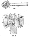
- FIGS. 1 and 2 there is illustrated a reversible ratchet wrench, generally designated by the numeral 10, constructed in accordance with and embodying the features of the present invention.
- the ratchet wrench 10 has an elongated handle 11 having formed unitary therewith at one end thereof a circular ratchet head 12, which has an enlarged circular bore or opening 13 formed axially therethrough and defining a cavity therein.
- a cylindrical array of equiangularly spaced-apart ratchet teeth (not shown).
- the bore 13 extends between opposite side surfaces of the head 12.
- the opposite side surfaces of the head 12 respectively have formed therein annular recesses or counterbores 14 and 17, the recess 14 having a substantially flat, planar annular end surface 15 and a cylindrical side surface 16, both substantially coaxial with the bore 13.
- the recess 17 has a planar, annular end surface 18 and a cylindrical side surface 19, both of which are substantially coaxial with the bore 13.
- a drive body 20 Disposed coaxially in the bore 13 for rotation about the axis thereof relative to the head 12 is a drive body 20, having a square drive lug 21 unitary therewith at one end thereof and projecting axially therefrom for engagement with an associated driven member, such as a socket, all in a known manner.
- the drive lug 21 may be provided with a depressible detent ball (not shown), also in a known manner.
- the drive body 20 is provided with a radially outwardly extending annular flange 22 dimensioned to be received in the annular recess 14 of the ratchet head 12.
- the flange 22 in turn, has an annular recess 23 formed therein, including a substantially planar annular end surface 24 and a cylindrical side surface 25, both arranged to be substantially coaxial with the bore 13 in the assembled condition of the parts.
- the drive body 20 has an end surface 26 formed at the other axial end thereof opposite the drive lug 21, the drive body 20 being dimensioned so that the end surface 26 is disposed axially inwardly of the annular recess 17 when the annular flange 22 is seated in the annular recess 14, as illustrated in FIG. 2 .
- the end surface 26 has a deep pawl recess 27 formed therein at one side thereof. Formed in the end surface 26 at the opposite side thereof is a shallower pin recess 28. Also formed in the end surface 26 intermediate the pawl recess 27 and the pin recess 28, substantially axially of the drive body 20, is a substantially rectangular recess 29. Formed centrally of the rectangular recess 27 and coaxially with the drive body 20 is an internally threaded cylindrical bore 29a.
- a pawl 30 Seated in the pawl recess 27 is a pawl 30.
- Formed on the outer side of the pawl 30 is an arcuate array of teeth (not shown) facing and dimensioned for meshing engagement with the ratchet teeth of the head 12.
- Formed on the opposite side of the pawl 30 is a flat rear surface 32 dimensioned for sliding engagement with the axial wall of the pawl recess 27.
- the pawl tooth array and the rear surface 32 thereof extend between flat, parallel, top and bottom surfaces 33 and 34 of the pawl 30.
- the ratchet wrench 10 is also provided with a reversing lever 40, generally in the shape of a circular disk having an axial bore 41 formed therethrough and surrounded at the upper end thereof with an annular recess 42.
- a reversing lever 40 Formed on the outer surface of the reversing lever 40 are three equiangularly spaced-apart and radially extending ribs 43.
- a cylindrical pin 45 Depending from the inner surface of the reversing lever 40 and spaced a predetermined distance radially outwardly from the bore 41 is a cylindrical pin 45, which is preferably unitary with the lever 40.
- the reversing lever 40 is dimensioned to be seated in the recess 17 of the head 12, the reversing lever 40 having an annular recess 47 in the inner surface thereof at the outer edge thereof, defining a planar, annular end surface 48 and a cylindrical side surface 49, both substantially coaxial with the bore 41.
- the reversing lever 40 is positioned on the head 12 so that the pin 45 is received in the pin recess 28, the bore 41 being coaxial with the drive body 20.
- the ratchet wrench 10 also includes a cylindrical bushing 50 dimensioned to be received through the bore 41 of the reversing lever 40 and into the rectangular recess 29 of the drive body 20.
- the bushing 50 has flats (not shown) formed on diametrically opposite sides thereof adjacent to the distal end thereof.
- the bushing 50 is provided adjacent to its outer end with a radially outwardly extending annular flange 53 which is seated in the recess 42 of the reversing lever 40 when the distal end of the bushing 50 is keyed into the rectangular recess 29.
- the flange 53 has formed on the outer surface thereof an indicator 54 ( FIG. 1 ).
- a screw 55 is receivable through the bushing 50 for threaded engagement in the threaded bore 29a, the screw 55 having an enlarged head 56 which seats against the annular flange 53.
- the screw 55 cooperates with the bushing 50 to hold the parts of the ratchet wrench 10 in an assembled condition, retaining the drive body 20 in the annular recess 14, and retaining the reversing lever 40 in the annular recess 17 of the ratchet head 12.
- the ratchet wrench 10 also includes a bias spring 60 in the form of an elongated wire spring member having a generally heart-shaped configuration, including a pair of opposed lobes 62 (one shown) and an apex 65, all lying in a plane substantially perpendicular to the axis of the drive body 20 between the reversing lever 40 and the drive body 20.
- a bias spring 60 in the form of an elongated wire spring member having a generally heart-shaped configuration, including a pair of opposed lobes 62 (one shown) and an apex 65, all lying in a plane substantially perpendicular to the axis of the drive body 20 between the reversing lever 40 and the drive body 20.
- anchor ends 66 one shown in FIG. 2
- the arrangement and operation of the parts of the ratchet wrench 10 described above are more fully described in the aforementioned U.S. patent no. 5,495,783 .
- annular recesses 14 and 17 on the ratchet head 12 cooperate, respectively, with the annular recess 23 of the drive body 20 and the annular recess 47 of the reversing lever 40, to define annular spaces 70 and 75, respectively accommodating annular seals 80 and 80A, which are of substantially identical construction, wherefore only one will be described in detail.
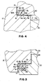
- Each of the seals 80, 80A is formed of a suitable flexible and resilient material, and has a body 81 which is generally rectangular in transverse cross section, having a generally cylindrical outer end wall 82 and annular top and bottom walls 83 and 84.
- two axially diverging lips 85 and 86 which extend, respectively, above and below the top and bottom walls 83 and 84.
- the seal 80 is disposed in the annular space 70, with the lips 85 and 86 thereof respectively engaging the annular end surface 15 of the ratchet head 12 and the annular end surface 24 on the drive body 20.
- the seal 80A is disposed in the annular spaced 75, with the lips 85 and 86 thereof respectively engaging the annular end surface 48 of the reversing lever 40 and the annular end surface 18 of the ratchet head 12.
- the seals 80 and 80A are axial seals, exerting sealing forces in axial directions for sealing lubricant in the cavity formed by the bore 13 and for preventing the entry of dust or dirt thereinto.
- this axial seal arrangement exerts substantially less rotational drag on the assembled parts than prior art radial seals. It is believed that this results, at least in part, from the fact that the double lip seal arrangement minimizes the surface contact between the seals 80 and 80A on the one hand, and the associated annular surfaces defining the annular spaces 70 and 75 on the other hand. It will be appreciated that, because of this axial compressive force, the seals 80 and 80A serve as bias members which cooperate to resiliently center the ratchet head 12 relative to the drive body 20 and the reversing lever 40, to prevent excessive drag or wear on any one side of the ratchet head 12.
- the seals 80 and 80A are formed of a material which is easily molded and which retains its compliance over a wide range of temperatures, even when in contact with petroleum-based lubricants.
- a material may be a nitrile polymer, although it will be appreciated that other suitable materials could be used.
Landscapes
- Engineering & Computer Science (AREA)
- Mechanical Engineering (AREA)
- Details Of Spanners, Wrenches, And Screw Drivers And Accessories (AREA)
- Gasket Seals (AREA)
- Mechanical Sealing (AREA)
- Sealing With Elastic Sealing Lips (AREA)
- Rotary Pumps (AREA)
Claims (19)
- Ensemble à rochet étanche (10) comprenant :une tête à rochet (12) avec une ouverture cylindrique (13) à travers celle-ci présentant un axe et définissant une cavité,une première surface d'épaulement annulaire (15) formée sur ladite tête à rochet (12) à une extrémité de la cavité coaxiale à celle-ci et s'étendant parallèlement à un plan disposé essentiellement perpendiculaire à l'axe,un mécanisme à rochet monté dans la cavité et comprenant un élément d'entraînement (20) monté pour une rotation relative à ladite tête à rochet (12) autour dudit axe et présentant une seconde surface d'épaulement annulaire (21) sur celui-ci faisant face à et espacée axialement de ladite première surface d'épaulement annulaire (15) essentiellement parallèle à celle-ci et coaxiale à celle-ci et coopérant avec celle-ci afin de définir un espace annulaire (70) entre elles, etun élément d'étanchéification (80) disposé dans ledit espace annulaire (70) et présentant un côté interne radialement et un côté externe radialement caractérisé en ce que deux lèvres flexibles et résilientes espacées axialement (85, 86), lesdites lèvres (85, 86) s'étendant radialement de l'un desdits côtés et étant respectivement engrenées avec lesdites surfaces d'épaulement (15, 24) pour coopérer avec celles-ci afin d'étanchéifier l'extrémité de la cavité.
- Ensemble à rochet (10) selon la revendication 1, dans lequel ledit élément d'étanchéification (80) comprend un corps d'étanchéification annulaire (81) présentant lesdits côtés et depuis lequel lesdites lèvres (85, 86) s'étendent.
- Ensemble à rochet (10) selon la revendication 2, dans lequel lesdites lèvres (85, 86) s'écartent dudit corps d'étanchéification (81).
- Ensemble à rochet (10) selon la revendication 2, dans lequel lesdites lèvres (85, 86) s'étendent radialement vers l'intérieur depuis ledit corps d'étanchéification (81).
- Ensemble à rochet (10) selon la revendication 4, dans lequel lesdites lèvres (85, 86) s'écartent axialement de ladite tête à rochet (12).
- Ensemble à rochet (10) selon la revendication 1, dans lequel lesdites lèvres (85, 86) s'écartent axialement de ladite tête à rochet (12).
- Ensemble à rochet (10) selon la revendication 1, et comprenant en outre un mécanisme de montage connectant ledit mécanisme à rochet à ladite tête à rochet (12).
- Ensemble à rochet (10) selon la revendication 7, dans lequel lesdites lèvres (85, 86) dudit élément d'étanchéification (80) forcent de manière résiliente ledit élément d'entraînement (20) et ledit corps à rochet (11) à s'écarter l'un de l'autre.
- Ensemble à rochet (10) selon la revendication 1,
dans lequel une troisième surface d'épaulement annulaire (18) est formée sur ladite tête à rochet (12) respectivement à une seconde extrémité de la cavité coaxiale à celle-ci et s'étendant parallèlement à un plan disposé essentiellement perpendiculaire à l'axe,
ledit mécanisme à rochet comprenant un élément d'inversion (40) monté pour une rotation relative à ladite tête à rochet (12) autour dudit axe et présentant une quatrième surface d'épaulement (48) sur celui-ci faisant face à et espacée axialement de ladite troisième surface d'épaulement annulaire (18) essentiellement parallèle à celle-ci et coaxiale à celle-ci pour coopérer avec celle-ci afin de définir un second espace annulaire (75) entre elles, et
un second élément d'étanchéification (80A) disposé dans ledit second espace annulaire (75) et présentant un second côté interne radialement et un second côté externe radialement et deux secondes lèvres flexibles et résilientes (85, 86) espacées axialement, lesdites secondes lèvres (85, 86) s'étendant radialement de l'un desdits seconds côtés et s'engrenant respectivement dans lesdites troisième (18) et quatrième surfaces d'épaulement (48) pour coopérer avec celles-ci afin d'étanchéifier la seconde extrémité de la cavité. - Ensemble à rochet (10) selon la revendication 9, dans lequel ladite tête à rochet (12) présente sur elle une rangée cylindrique de dents d'arrêt définissant ladite ouverture (13), ledit mécanisme à rochet comprenant un mécanisme d'encliquetage monté pour un engrènement à rochet avec lesdites dents d'arrêt.
- Ensemble à rochet (10) selon la revendication 9, et comprenant en outre une structure d'accouplement interconnectant ledit élément d'entraînement (20) et ledit élément d'inversion (40) pour les retenir sur ladite tête à rochet (12) respectivement aux première et seconde extrémités de la cavité.
- Ensemble à rochet (10) selon la revendication 11, dans lequel lesdits premier (80) et second éléments d'étanchéification (80A) forcent respectivement de manière résiliente ledit élément d'entraînement (20) et ledit élément d'inversion (40) à s'éloigner axialement dudit corps à rochet (12) pour centrer ledit mécanisme à rochet par rapport à ladite tête à rochet (12).
- Ensemble à rochet (10) selon la revendication 9, dans lequel ledit premier élément d'étanchéification (80) comprend un premier corps d'étanchéification annulaire (81) duquel les premières lèvres (85, 86) s'étendent, et ledit second élément d'étanchéification (80A) comprend un second corps d'étanchéification annulaire (81) duquel les secondes lèvres (85, 86) s'étendent.
- Ensemble à rochet (10) selon la revendication 13, dans lequel sur chacun desdits premier (80) et second éléments d'étanchéification (80A), les lèvres (85, 86) de celui-ci s'écartent du corps d'étanchéification (81) de celui-ci.
- Ensemble à rochet (10) selon la revendication 13, dans lequel sur chacun desdits premier (80) et second éléments d'étanchéification (80A), les lèvres (85, 86) de celui-ci s'étendent radialement vers l'intérieur depuis le corps d'étanchéification (81) de celui-ci.
- Ensemble à rochet (10) selon la revendication 15, dans lequel sur chaque élément d'étanchéification (80, 80A), lesdites lèvres (85, 86) s'écartent axialement de ladite tête à rochet (12).
- Ensemble à rochet (10) selon la revendication 9, dans lequel sur chaque élément d'étanchéification (80, 80A), lesdites lèvres (85, 86) s'écartent axialement de ladite tête à rochet (12).
- Ensemble à rochet (10) selon la revendication 2, dans lequel ladite tête à rochet (12) et ledit élément d'entraînement (20) présentent respectivement des surfaces cylindriques limitant ledit espace annulaire (70), ledit corps d'étanchéification (81) étant disposé dans un engrènement étanchéifiant avec l'une desdites surfaces cylindriques.
- Ensemble à rochet (10) selon la revendication 13, dans lequel ladite tête à rochet (12) et ledit élément d'entraînement (20) présentent respectivement une première (15) et seconde (24) surfaces cylindriques limitant ledit premier espace annulaire (70) et une troisième (18) et quatrième (48) surfaces cylindriques limitant ledit second espace annulaire (75), ledit premier corps d'étanchéification (80) étant disposé dans un engrènement étanchéifiant avec l'une desdites première et seconde surfaces cylindriques et ledit second corps d'étanchéification (80A) étant disposé dans un engrènement étanchéifiant avec l'une desdites troisième et quatrième surfaces cylindriques.
Applications Claiming Priority (4)
| Application Number | Priority Date | Filing Date | Title |
|---|---|---|---|
| US08/984,764 US5921158A (en) | 1997-12-04 | 1997-12-04 | Sealed reversible ratchet wrench |
| US984764 | 1997-12-04 | ||
| CA002223777A CA2223777C (fr) | 1997-12-04 | 1997-12-05 | Cle a rochet reversible etanche |
| PCT/US1998/025339 WO1999028091A1 (fr) | 1997-12-04 | 1998-11-30 | Cle a rochet |
Publications (3)
| Publication Number | Publication Date |
|---|---|
| EP1051284A1 EP1051284A1 (fr) | 2000-11-15 |
| EP1051284A4 EP1051284A4 (fr) | 2007-05-02 |
| EP1051284B1 true EP1051284B1 (fr) | 2010-01-20 |
Family
ID=31716421
Family Applications (1)
| Application Number | Title | Priority Date | Filing Date |
|---|---|---|---|
| EP98960540A Expired - Lifetime EP1051284B1 (fr) | 1997-12-04 | 1998-11-30 | Cle a rochet |
Country Status (6)
| Country | Link |
|---|---|
| US (1) | US5921158A (fr) |
| EP (1) | EP1051284B1 (fr) |
| JP (1) | JP4357740B2 (fr) |
| AU (1) | AU743330B2 (fr) |
| CA (1) | CA2223777C (fr) |
| WO (1) | WO1999028091A1 (fr) |
Cited By (2)
| Publication number | Priority date | Publication date | Assignee | Title |
|---|---|---|---|---|
| CN102380839A (zh) * | 2010-09-06 | 2012-03-21 | 胡厚飞 | 棘轮扳手的防尘结构 |
| TWI462803B (fr) * | 2012-08-28 | 2014-12-01 |
Families Citing this family (24)
| Publication number | Priority date | Publication date | Assignee | Title |
|---|---|---|---|---|
| US6125722A (en) * | 1999-03-18 | 2000-10-03 | Snap-On Tools Company | Ratchet wrench with sealed reversing lever |
| US6260448B1 (en) * | 1999-12-21 | 2001-07-17 | Hand Tool Design Corporation | Top load ratchet wrench |
| WO2002034472A2 (fr) * | 2000-10-20 | 2002-05-02 | Joda Enterprises, Inc. | Cle a rochet scellee |
| WO2002034474A1 (fr) * | 2000-10-26 | 2002-05-02 | Joda Enterprises, Inc. | Cle a cliquet etanche |
| US7014023B1 (en) * | 2003-04-17 | 2006-03-21 | Gauthier Biomedical, Inc. | No-play ratchet construction |
| US6981435B2 (en) * | 2003-05-08 | 2006-01-03 | Chih-Ching Hsien | Ratchet wrench having a sealing structure |
| US7181997B1 (en) | 2005-01-18 | 2007-02-27 | Pilling Weck, Incorporated | Ratchet screwdriver and method of making same |
| US7353735B2 (en) * | 2005-06-02 | 2008-04-08 | The Stanley Works | Ratchet wrench |
| ES2303414B1 (es) * | 2005-10-11 | 2009-11-18 | Herramientas Eurotools, S.A. | Llave de carraca reversible. |
| DE102008006914A1 (de) | 2008-01-24 | 2009-07-30 | Adolf Würth GmbH & Co. KG | Schraubenschlüssel |
| DE102008041911A1 (de) | 2008-09-09 | 2010-03-11 | Adolf Würth GmbH & Co. KG | Ratschenschlüssel |
| TW201028252A (en) * | 2009-01-23 | 2010-08-01 | Hou-Fei Hu | Dustproof ratchet wrench |
| CN101797731B (zh) * | 2009-02-05 | 2011-11-16 | 胡厚飞 | 防尘棘动扳手 |
| TW201034801A (en) * | 2009-03-17 | 2010-10-01 | Hou-Fei Hu | Dustproof ratchet wrench |
| US8539864B1 (en) | 2010-08-25 | 2013-09-24 | Justin A. Kennedy | Dual-handled drive wrench |
| CN102528745A (zh) * | 2012-02-27 | 2012-07-04 | 福建省南平铝业有限公司 | 一种拧头扳手 |
| US10118279B2 (en) | 2012-08-28 | 2018-11-06 | Bobby Hu | Ratchet wrench with dustproof structure |
| TWI530368B (zh) * | 2014-10-03 | 2016-04-21 | 史丹利七和國際股份有限公司 | 棘輪扳手 |
| TWI551403B (zh) * | 2015-12-15 | 2016-10-01 | Apex Tool Hk Ltd | A ratchet wrench with a dustproof structure |
| TWI581910B (zh) * | 2016-02-01 | 2017-05-11 | Yi-He Liao | Dust-proof ratchet wrench construction (2) |
| GB2550922A (en) * | 2016-05-31 | 2017-12-06 | Stanley Middle East FZE | A wrench with a ratchet mechanism |
| TWI597131B (zh) * | 2016-11-18 | 2017-09-01 | Dust-proof hand tools | |
| US11331774B2 (en) | 2019-09-30 | 2022-05-17 | Harbor Freight Tools Usa, Inc. | Ratchet tool with improved pawl |
| TWM590507U (zh) * | 2019-10-09 | 2020-02-11 | 宥豪事業有限公司 | 棘輪扳手 |
Family Cites Families (18)
| Publication number | Priority date | Publication date | Assignee | Title |
|---|---|---|---|---|
| US2188846A (en) * | 1938-10-14 | 1940-01-30 | Sherman Klove Co | Ratchet device |
| US2395681A (en) * | 1944-11-08 | 1946-02-26 | Duro Metal Prod Co | Ratchet mechanism |
| US2957377A (en) * | 1957-09-13 | 1960-10-25 | Terence G Hare | Reversible ratchet type wrench |
| DE6935414U (de) * | 1968-09-16 | 1971-09-23 | Skf Svenska Kullagerfab Ab | Dichtungsanordnung fuer ein axial geteiltes lagergehaeuse. |
| US3677102A (en) * | 1970-06-02 | 1972-07-18 | Usag Spa Gemonio | Free-wheel device for transmitting torques and reversible ratchet dog comprising same |
| US4122921A (en) * | 1977-11-10 | 1978-10-31 | Rockwell International Corporation | Flexible seal for brakes |
| US4257507A (en) * | 1978-08-15 | 1981-03-24 | Jo-Line Tools, Inc. | Torque wrench with pawl guide |
| US4434863A (en) * | 1979-05-14 | 1984-03-06 | Smith International, Inc. | Drill string splined resilient tubular telescopic joint for balanced load drilling of deep holes |
| US4480703A (en) * | 1979-08-24 | 1984-11-06 | Smith International, Inc. | Drilling head |
| US4301897A (en) * | 1979-12-13 | 1981-11-24 | Cox Jr Frank T | Slack adjuster |
| US4347767A (en) * | 1981-01-06 | 1982-09-07 | Gentiluomo Joseph A | Ratcheting device |
| US4491043A (en) * | 1981-03-10 | 1985-01-01 | Dempsey John D | Stepless wrench including quick release mechanism |
| US4484732A (en) * | 1982-06-01 | 1984-11-27 | Gould Larry D | Constant and variable force tensioning devices utilizing atmospheric pressure |
| US4497227A (en) * | 1983-01-27 | 1985-02-05 | Js Technology, Inc. | Reversible ratchet mechanism |
| GB2231104B (en) * | 1989-03-11 | 1993-08-25 | Dowty Seals Ltd | Seal for a hydraulic ram |
| US4934220A (en) * | 1989-04-03 | 1990-06-19 | Snap-On Tools Corporation | Sealed reversible ratchet wrench |
| US5495783A (en) * | 1994-07-08 | 1996-03-05 | Snap-On Incorporated | Reversible ratchet wrench with direction indicia |
| US5636557A (en) * | 1996-05-24 | 1997-06-10 | Ma; Nai-Lin | Ratchet type ring spanner |
-
1997
- 1997-12-04 US US08/984,764 patent/US5921158A/en not_active Expired - Lifetime
- 1997-12-05 CA CA002223777A patent/CA2223777C/fr not_active Expired - Lifetime
-
1998
- 1998-11-30 EP EP98960540A patent/EP1051284B1/fr not_active Expired - Lifetime
- 1998-11-30 AU AU16117/99A patent/AU743330B2/en not_active Ceased
- 1998-11-30 WO PCT/US1998/025339 patent/WO1999028091A1/fr active IP Right Grant
- 1998-11-30 JP JP2000523045A patent/JP4357740B2/ja not_active Expired - Lifetime
Cited By (3)
| Publication number | Priority date | Publication date | Assignee | Title |
|---|---|---|---|---|
| CN102380839A (zh) * | 2010-09-06 | 2012-03-21 | 胡厚飞 | 棘轮扳手的防尘结构 |
| CN102380839B (zh) * | 2010-09-06 | 2013-11-20 | 胡厚飞 | 棘轮扳手的防尘结构 |
| TWI462803B (fr) * | 2012-08-28 | 2014-12-01 |
Also Published As
| Publication number | Publication date |
|---|---|
| US5921158A (en) | 1999-07-13 |
| JP4357740B2 (ja) | 2009-11-04 |
| EP1051284A1 (fr) | 2000-11-15 |
| CA2223777C (fr) | 2006-08-29 |
| AU743330B2 (en) | 2002-01-24 |
| JP2001524654A (ja) | 2001-12-04 |
| EP1051284A4 (fr) | 2007-05-02 |
| WO1999028091A1 (fr) | 1999-06-10 |
| AU1611799A (en) | 1999-06-16 |
| CA2223777A1 (fr) | 1999-06-05 |
Similar Documents
| Publication | Publication Date | Title |
|---|---|---|
| EP1051284B1 (fr) | Cle a rochet | |
| US5495783A (en) | Reversible ratchet wrench with direction indicia | |
| US4934220A (en) | Sealed reversible ratchet wrench | |
| US6260448B1 (en) | Top load ratchet wrench | |
| AU2008229098B2 (en) | Dual pawl ratchet mechanism and reversing method | |
| US4602534A (en) | Ratchet wrench | |
| US6539825B1 (en) | Single direction ratcheting wrench with stuck prevention and ratcheting direction indication | |
| US8342059B2 (en) | Dustproof seal for ratchet wrench | |
| US6644148B2 (en) | Reversible ratchet-type wrench | |
| US4030384A (en) | Ratchet wrench | |
| US4562757A (en) | High torque expandable socket ratchet wrench | |
| US20110308359A1 (en) | Dustproof Device for Ratchet Wrench | |
| US6082512A (en) | Selectable one way stepless clutch | |
| US6510765B2 (en) | Structure of a ratchet wheel having a ratchet wheel allowing a smooth teeth returning after application of the ratchet wrench | |
| US20050051002A1 (en) | Sealed powered ratchet wrench | |
| MXPA00005517A (en) | Sealed reversible ratchet wrench | |
| US20230311276A1 (en) | Ratchet mechanism and hand tool | |
| EP1426144B1 (fr) | Clé à cliquet unidirectionnel | |
| EP0733438A1 (fr) | Dispositif de transmission de couple et clé | |
| CA3143466A1 (fr) | Mecanisme a declic et rochet | |
| TW202019625A (zh) | 棘輪扳手 | |
| AU2005100450A4 (en) | Loose-proof screw bolt | |
| WO2003039813A1 (fr) | Cle | |
| KR19990071323A (ko) | 렌취 | |
| JPH05503881A (ja) | 動力工具 |
Legal Events
| Date | Code | Title | Description |
|---|---|---|---|
| PUAI | Public reference made under article 153(3) epc to a published international application that has entered the european phase |
Free format text: ORIGINAL CODE: 0009012 |
|
| 17P | Request for examination filed |
Effective date: 20000628 |
|
| AK | Designated contracting states |
Kind code of ref document: A1 Designated state(s): DE FR GB IT |
|
| A4 | Supplementary search report drawn up and despatched |
Effective date: 20070209 |
|
| 17Q | First examination report despatched |
Effective date: 20080619 |
|
| GRAP | Despatch of communication of intention to grant a patent |
Free format text: ORIGINAL CODE: EPIDOSNIGR1 |
|
| GRAS | Grant fee paid |
Free format text: ORIGINAL CODE: EPIDOSNIGR3 |
|
| GRAA | (expected) grant |
Free format text: ORIGINAL CODE: 0009210 |
|
| AK | Designated contracting states |
Kind code of ref document: B1 Designated state(s): DE FR GB IT |
|
| REG | Reference to a national code |
Ref country code: GB Ref legal event code: FG4D |
|
| REF | Corresponds to: |
Ref document number: 69841465 Country of ref document: DE Date of ref document: 20100311 Kind code of ref document: P |
|
| PLBE | No opposition filed within time limit |
Free format text: ORIGINAL CODE: 0009261 |
|
| STAA | Information on the status of an ep patent application or granted ep patent |
Free format text: STATUS: NO OPPOSITION FILED WITHIN TIME LIMIT |
|
| 26N | No opposition filed |
Effective date: 20101021 |
|
| REG | Reference to a national code |
Ref country code: FR Ref legal event code: PLFP Year of fee payment: 18 |
|
| REG | Reference to a national code |
Ref country code: FR Ref legal event code: PLFP Year of fee payment: 19 |
|
| REG | Reference to a national code |
Ref country code: FR Ref legal event code: PLFP Year of fee payment: 20 |
|
| PGFP | Annual fee paid to national office [announced via postgrant information from national office to epo] |
Ref country code: FR Payment date: 20171127 Year of fee payment: 20 Ref country code: DE Payment date: 20171129 Year of fee payment: 20 |
|
| PGFP | Annual fee paid to national office [announced via postgrant information from national office to epo] |
Ref country code: GB Payment date: 20171127 Year of fee payment: 20 Ref country code: IT Payment date: 20171123 Year of fee payment: 20 |
|
| REG | Reference to a national code |
Ref country code: DE Ref legal event code: R071 Ref document number: 69841465 Country of ref document: DE |
|
| REG | Reference to a national code |
Ref country code: GB Ref legal event code: PE20 Expiry date: 20181129 |
|
| PG25 | Lapsed in a contracting state [announced via postgrant information from national office to epo] |
Ref country code: GB Free format text: LAPSE BECAUSE OF EXPIRATION OF PROTECTION Effective date: 20181129 |